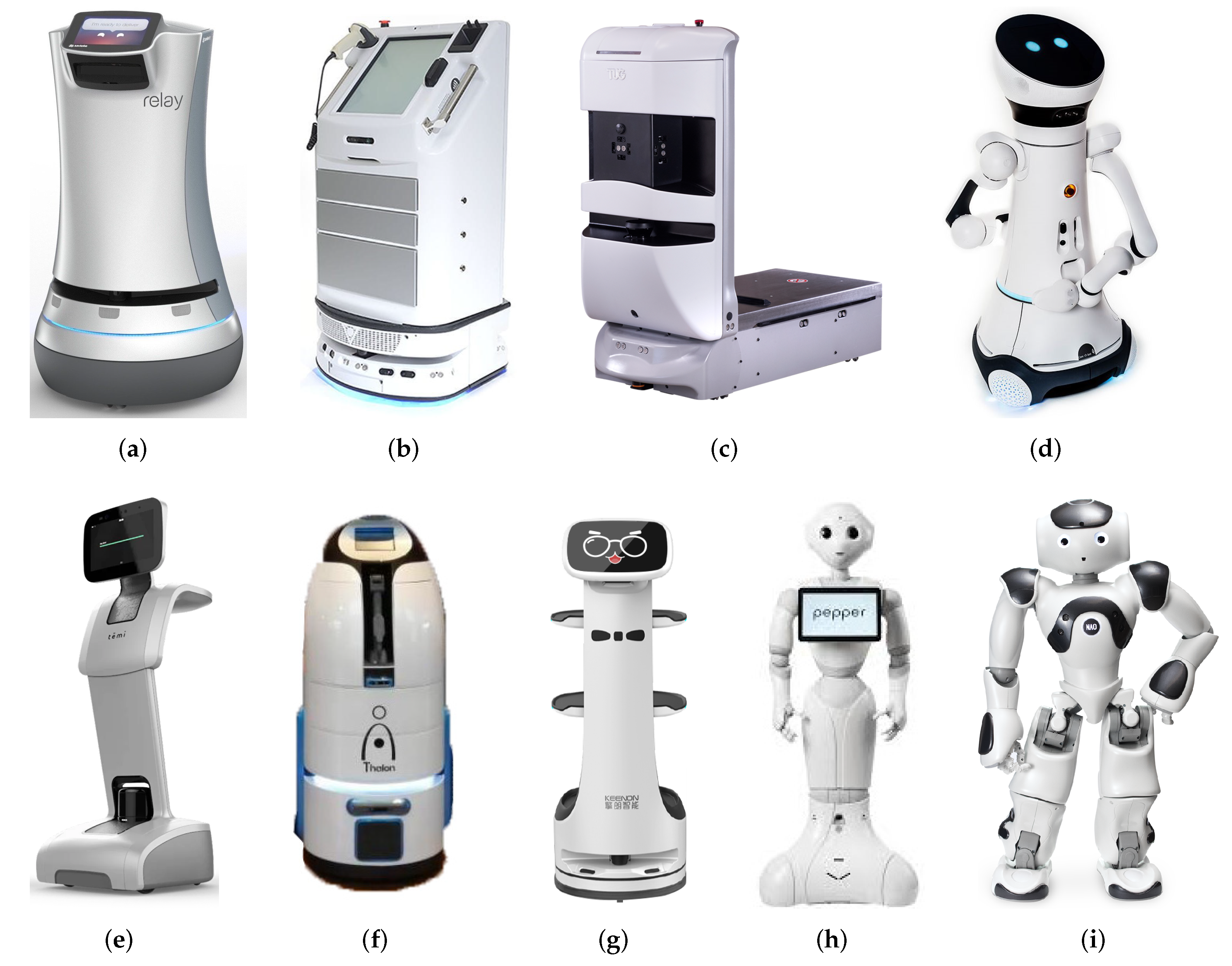
This section will present the different constituent parts of the robot. In the the first subsection, a comparison of the sensors selected and implemented, an explanation of their operation and a comparison with other options will be made. The second subsection explains the implemented software and the capabilities that it allows the robot to develop.
2.1. Hardware Considerations
This section presents all the hardware components that passed the four filters imposed for this research: The first filter is that the hardware element (sensor, actuator, processor, case among others) meets the technical requirements explained in the tables of the finalist details in the selection. The second filter, which is the most restrictive, is that the price of this component must be the minimum possible while maintaining the standards of filter 1. The third filter is the availability of this part in the local market or that the supplier allows easy shipment to South America-Ecuador. Finally, but probably most importantly, that it is in line with the end user’s preferences. If the hardware component did not meet these three requirements it was discarded even though they stood out in any of the three criteria above the others. Therefore, in this section, only the components that met the four filter criteria are presented, explaining their final selection.
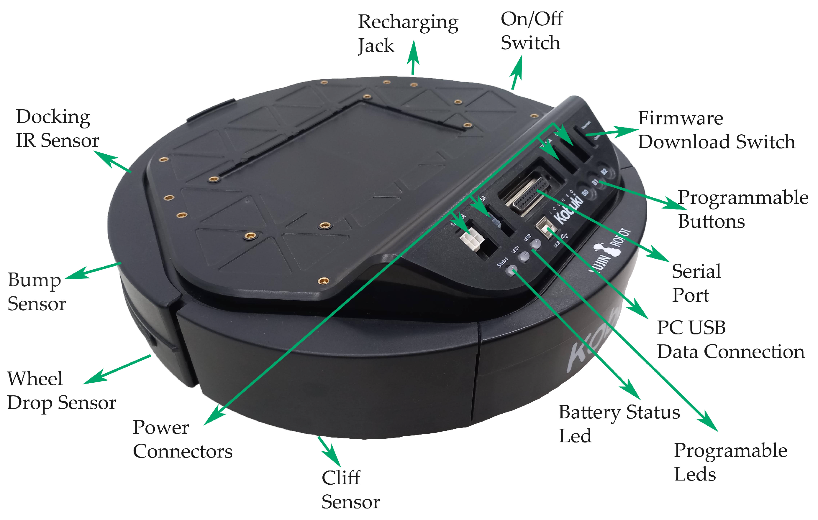
The mobile robot platform selected was iClebo Kobuki
Figure 3, manufactured in Korea by Yujin Robot Co, Ltd. [
46], because after a comparison with the iCreate 2 base of the manufacturer iRobot, it was found that Kobuki has more significant resources available in hardware and software in Robot Operating System (ROS) [
47], so it has a greater possibility of action and versatility when testing for research and development purposes
Table 1.
To process all the information received by the different peripherals, an Intel NUC i5 with 8 GB of RAM was installed in the first instance. Still, due to the amount of information processed simultaneously, especially when performing simulations in the GAZEBO application and visualizations in RVIZ, the machine would not respond and would freeze. Similarly, when using the camera functions in conjunction with the mobile robot base, the camera image was lost or turned off, due to the above, the equipment was upgraded to an INTEL NUC i7 with 16 GB of RAM. By making this change, a significant improvement was obtained. However, there is still no total fluency when running several functions of the robots simultaneously, especially simulations. For operation only with the physical robot the computer is adequate. If it is possible to increase the ram to 64 GB and add an external graphics card would be recommendable improvement.
In the camera section, a physical comparison was made between two options: Orbbec Astra camera and Intel RealSense D435i
Figure 4, both of which fit very well with the robot. Considering mainly the range of vision, price, support and compatibility with the operating system used, the Orbbec was chosen. The improvements presented by the D435i in terms of image quality, weight, dimensions and even the inclusion of the IMU (Inertial Measurement Unit) [
49], which is a helpful element with the capacity to measure and report the specifications of the orientation, speed and gravitational forces that the equipment can suffer, were insufficient in the cost-benefit analysis in
Table 2. One problem to consider with the Intel camera is that it still has compatibility issues with the Kinect version of ROS, but not with the Melodic and Noetic versions.
When analyzing what type of laser scanner to use, three elements were taken into consideration. The first one was the Hokuyo UST-20LX which is an excellent piece of equipment with the best features and performance, but with a high cost for this application, it was discarded. So an option in line with a low-cost robot is the one offered by Slamtec. It was decided to install the RPLIDAR A3, its range, scanning frequency, and weight are sufficient for this robot and a considerable improvement over the previous version, the RPLIDAR A2, which was also considered as shown in
Table 3.
For the screen, there are two GeChic portable touchscreen monitors with similar characteristics, the only difference being their size, 13.3 and 11.3 inches. The 13.3″ monitor was installed as it is considered to be better visualized due to its large size, but when carrying out tests it was noted that it presents complications due to its volume and weight, as it must be on top of the robot to be able to interact with people and this generates instability in the structure, which can be seen when moving along paths that are not wholly smooth. For future versions, the 11.3-inch monitor will be considered.
When testing in natural environments, the energy consumed by all constituent elements of CeCi, exceeded the capacity provided by the two batteries included in the Kobuki base. With this configuration, the robot’s autonomy in constant activity is 15 min and 25 min at rest. To solve this problem, an external 50,000 mAh Krisdonia battery Power Bank was included, which added autonomy of 4 h of continuous activity and 5 h and 30 min when idle. The external battery provides the power supply for the NUC computer, touch screen, lidar sensor, and camera. Therefore, the sensors and motors integrated in the mobile base are powered by the internal kobuki batteries, giving the mobile base an autonomy of 5 h of continuous activity on a flat surface and autonomy of 7 h at rest.
Table 4 compares the batteries used, and
Table 5 shows the consumption of the main peripherals of the robot.
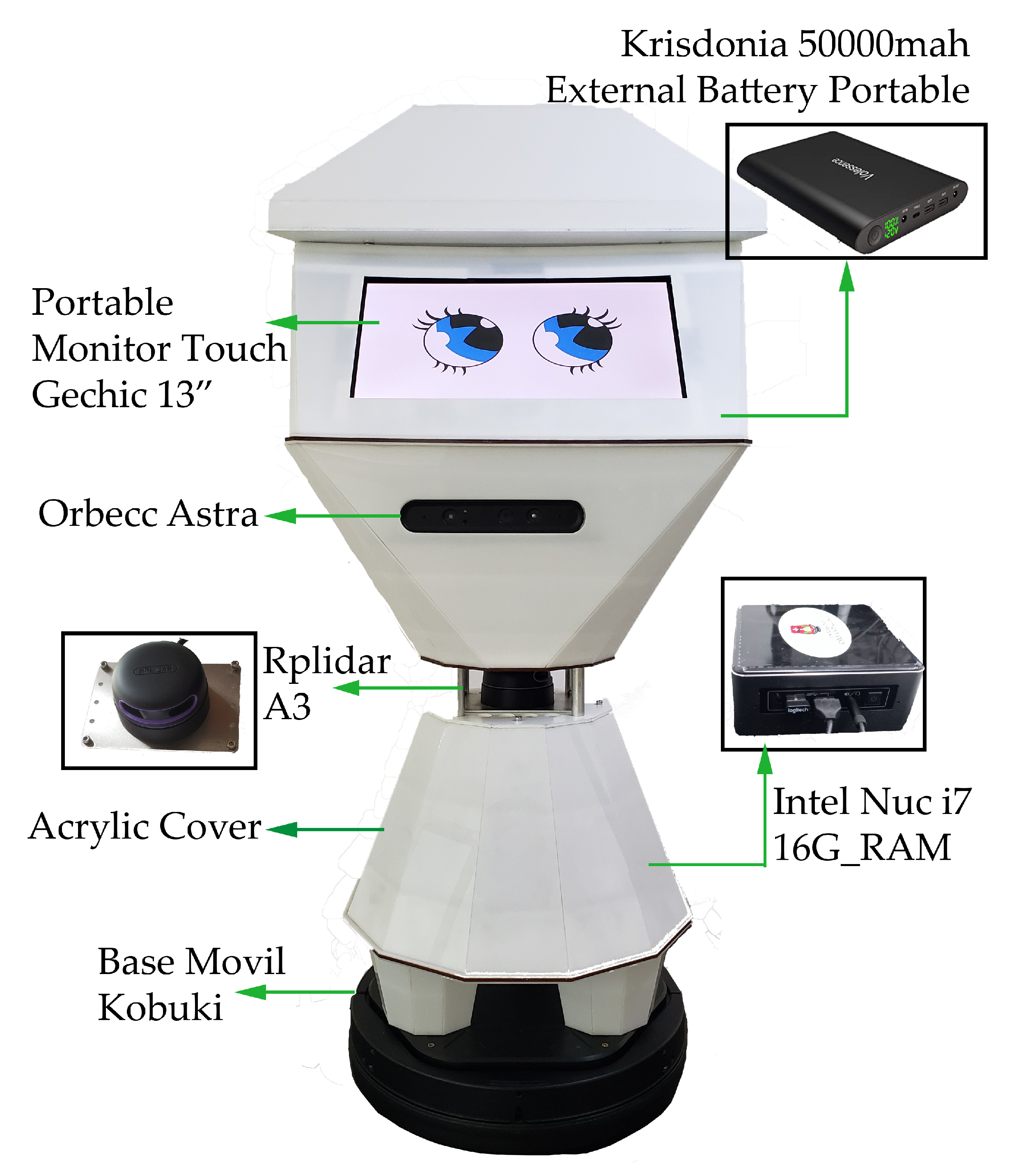
Figure 5 illustrates the hardware parts mentioned with their respective locations on the robot.
2.2. Software Considerations
Since the idea of making CeCi was generated, the open source platform Ubuntu 16.04 LTS was used, the version with long-term support [
4]. During the course of the research several tests were carried out. One of them was to upgrade to 18.04 and even to version 20.04 but when installing and testing, it was found that it does not have compatibility with several packages necessary for the robot to fulfill the projected functions, so the development was continued in Ubuntu 16.04 LTS. Currently, CeCi software is supported on Ubuntu 20.04 LTS except for the navigation system, which is still in the process of being adapted. However, commercially available robots such as Temi, among others, are still using Ubuntu 16.04 for reliability.
It is crucial to consider the right environment for working in ROS, which is not an operating system in the most common sense of programming and process management. Instead, it provides a structured communication layer at a higher level than the host operating systems. So there are several structured versions and each is compatible with a different version of Ubuntu, in this case, the version compatible with the 16.04 LTS operating system is ROS Kinetic [
51].
For a clear understanding of the software that enables the operation of the social robot, some remarks about ROS are necessary [
52,
53]: This framework provides services such as hardware drivers, device control, implementation of resources commonly used in robotics, message passing between processes and packet maintenance. It is based on a graph architecture where the processing takes place in nodes that can receive, send and multiplex messages from sensors, control, states, planning, and actuators, among others. These messages are called topics or services.
ROS is organized in terms of its software in (a) the operating system part, ROS, and (b) the ROS package that the user programmers contribute. Packages can be grouped into sets called stacks. Within the packages are the nodes to be executed.
Figure 6 illustrates the above.
The Robotic Operating System (ROS) is free software that is based on an architecture where processing takes place in nodes [
54] that can receive, send and multiplex messages from: sensors, control, states, schedules, and actuators, among others. The ease of integrating various functions [
55] and utilities through its topical system (internal communication) [
56] exemplified in
Figure 6, makes it very appropriate for the development of algorithms and the progress of research in robotics-related subjects [
57]. Although it is not an operating system, ROS provides the standard services of an operating system, such as: hardware abstraction, low-level device control, implementation of commonly used functionality, inter-process message passing, and package maintenance.
The CeCi software system is based on the structure provided by ROS in Packages, Nodes, Topics and Services. The following is an explanation by functional parts respecting the ROS architecture. The complete diagram of the Robot software was extracted from ROS using its graphical tool rqt_graph (node, topic and service diagram) and is included in
Figure A1.
The main packages used for CeCi are Kobuki and Turtlebot 2 from the Yujim Robot manufacturer. There was no major problem because the ROS version used has support.
The Kobuki package allows to control and read the sensors of the mobile robotic base of the same name in detail, the utilities used are:
Automatic return to its charging base;
Publish bumpers and cliff sensors events as a pointcloud so navistack can use them;
URDF and Gazebo model description of Kobuki;
Keyboard teleoperation for Kobuki;
A ROS node wrapper for the kobuki driver;
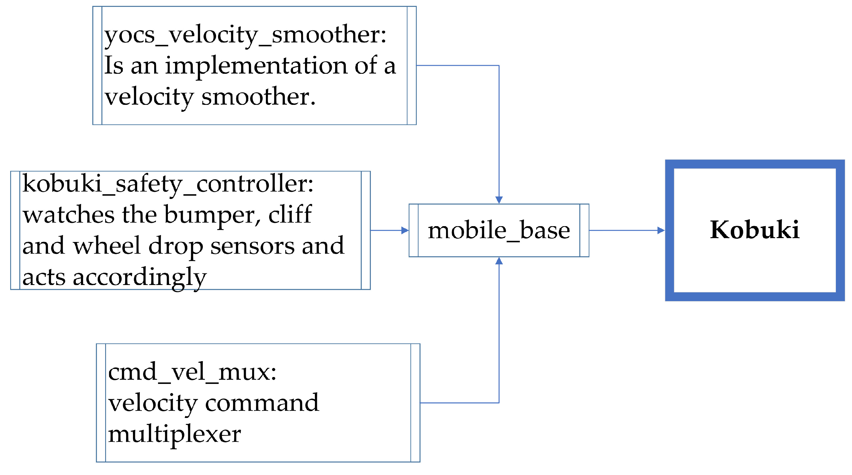
Watches the bumper, cliff, and wheel drop sensor to allow safe operation;
Set of tools to thoroughly test Kobuki hardware [
58].
Figure 7 shows in a diagram the main functions contained in the package.
The closest robot to CeCi in terms of peripherals is the Turtlebot 2 [
59], so this robot package was used as a basis. The Turtlebot package integrates all the functionalities of the Kobuki package plus those of the packages linked to the drivers and functionalities of the 3D camera (openni2_camera package) and the lidar sensor (rplidar package). In addition, special function (navigation) is used, which can be found in the turtlebot package developed by Gaitech. The
Figure 8 illustrates the above.
This explains the robot capabilities for: (a) commanding and sensing its mobile base, (b) reading sensors and odometry including the lidar sensor and 3D camera Turtlebot Package, (c) navigation using the functions implemented within the Gaitech package.
The following explains the packages needed to perform navigation with Ceci. The first requirement is to have a 2D map of the environment in which you want the robots to navigate. A previously defined .yaml file can provide the map, or the robot can explore its environment and generate one.
To survey an environment in a 2D plane, two methods were implemented. The first one uses the Hector SLAM package [
60,
61] and the RPLIDAR A3 laser sensor. The second method implemented uses the SLAM Gmapping package and the Orbbec Astra 3D Camera as a sensor.
Figure 9 illustrates the results obtained with each method, as it is evident that the first one gives better results.
Hector SLAM is an approach that adopts a 2D SLAM system based on the integration of laser scans (LIDAR) on a flat map and a 3D navigation system that integrates an inertial measurement unit (IMU) [
62], to incorporate the 2D information from the SLAM subsystem as a probable source of information. It is based on optimizing the alignment of the beam ends with the map learned so far. The basic idea uses a Gauss–Newton approach inspired by the work in computer vision explained in [
63]. Using this approach, there is no need for a data association search between the endpoints of the beam. As the scans are aligned with the existing map, the matching is implicitly performed with all previous scans in real-time triggered by the refresh rate of the laser scanning device. Both estimates are individually updated and flexibly matched to remain synchronized over time, giving precise results.
The SLAM Gmapping method focuses on using a Rao–Blackwellized Particle Filter (RBPF) [
64] in which each particle contains an individual map of the environment, considering not only the robot’s motion, but also the robot’s current environment. This minimizes the uncertainty about the robot’s position in the step-by-step filter prediction and considerably reduces the number of required samples [
65]. That is, it computes a highly accurate proposal distribution that is based on the observation probability of the most recent sensor information, odometry, and a matching process in the [
66] sweep.
The package AMCL (Adaptive Monte Carlo Localization) is a probabilistic localization module which estimates the position and orientation of the CeCi robot in a given known map using a 2D laser scanner [
67,
68,
69].
Each package fulfills a specific purpose and within them run nodes that contribute to the execution of that purpose. However, this does not limit the communication between nodes of different packages. Therefore all of them contribute to the complete task executed by the robot [
70].
To control the navigation to specific points on a given map, a command file was formulated based on the map navigation file produced by Gaitech edu [
71]. This script makes it possible to register coordinates as fixed points where the robot has to go. For this purpose, it uses its odometry and simultaneous localization [
72], receiving orders or commands by different methods, either by keyboard, voice commands and mobile application.
Summarised from the navigation
Figure 10, it can be understood from this short list of processes that CeCi fulfils the following points:
- 1.
The map of the previously surveyed site (map_server) is entered;
- 2.
The state of a robot is published in tf. When this is done the state of the robot is available to all components in the system that also use tf [
72];
- 3.
The navigation command is executed by voice command, keyboard or mobile application;
- 4.
Probabilistic localization (AMCL) system for the robot to move, senses all its environment;
- 5.
Evaluates the best route to the target (Motion planning);
- 6.
Performs a diagnosis of the environment (Mapping), receives the command and the traced route to proceed to move the robot;
- 7.
While the robot follows the route the sensors keep working to avoid obstacles [
73] and unevenness(SLAM) [
66,
74].
Orders received by the robot have three possibilities of input:
Voice Commands: For the input of the information it is done through the package called Pocketsphinx, which is a continuous voice recognition system, it works independent of the speaker, based on discrete Hidden Markov Models (HMM) [
75]. This system is based on the open source CMU Sphinx-4, developed by Carnegie Mellon University in Pittsburgh–Pennsylvania [
76]. Through a Python script, sentences and commands are configured so that CeCi can perform movements and answers to the different preconfigured questions in the user’s language (Spanish). In order for CeCi to understand the commands dictated in Spanish, the training was taken from [
77], since more than 450 h were invested in creating the language recognition files to form a complete dictionary, overcoming eventualities specific to Spanish.
Keyboard: It is the minor complex of all, since only information is entered to a terminal through a keyboard connected by Bluetooth to the Intel Nuc computer inside the robot [
78].
Application: The ROS MOBILE application is a very intuitive and customizable open source user interfaces with the option to control and monitor the robotic system. In this case, a proprietary user interface was developed for Ceci with cursors and buttons for predefined motion functions. The connection is through a WiFi–Internet network between the robot and any mobile device (smartphones or tablets).


