Article

An Effective Design Formula for Single-Layer Printed Spiral Coils with the Maximum Quality Factor (Q-Factor) in the Megahertz Frequency Range

Korea Electrotechnology Research Institute, An-San 15588, Korea
*
Author to whom correspondence should be addressed.
Sensors 2022, 22(20), 7761; https://doi.org/10.3390/s22207761
Submission received: 25 August 2022 / Revised: 5 October 2022 / Accepted: 10 October 2022 / Published: 13 October 2022
(This article belongs to the Section Physical Sensors)

Abstract

:
This paper presents a design formula for a printed spiral coil to ensure the maximum quality factor (Q-factor). The formula is composed of a pattern’s metal thickness, single pattern width, total pattern width, and turn number, and is effective in the megahertz (MHz) frequency range. During the formula’s design, the resistance, self-inductance, and Q-factor are calculated according to the ratio of each pattern’s width and total pattern width and the turn number for different metal thicknesses, frequencies, and total pattern widths using a volume filament model (VFM). With a given turn number and metal thickness, the optimal ratio of individual and total pattern widths can be determined to ensure the maximum Q-factor. To verify the formula, some optimal coils were fabricated, and the calculations and measurements were shown to have good agreement. Furthermore, the optimized coils were shown to have higher coupling efficiency than the coils without optimal dimensions.

1. Introduction

An effective coil with an improved quality factor (Q-factor) is essential in magnetic resonance wireless power transfer (MR-WPT). The Q-factor of a coil (=2πfL/R) is calculated from its frequency (f), self-inductance (L), and losses (R). Therefore, it is important to design a coil with higher self-inductance and lower losses in the megahertz (MHz) frequency range.
Coil losses mainly consist of skin resistance and proximity resistance in the MHz frequency range. The skin effect is caused by an eddy current in a metal wire, which then increases skin resistance [1] at higher frequencies. The proximity effect also results from the current induced in the metal wire via a magnetic field generated by neighboring metal wires. This effect reduces the effective area of the current flow, leading to a very quick increase in ohmic resistance, especially when many wires are bundled tightly. Therefore, a metal wire is preferable to a Litz wire in the MHz frequency range.
In the MHz frequency range, a printed spiral coil is very often used for the MR-WPT of biomedical sensors, Internet-of-Things devices, and consumer devices owing to its easy fabrication and compactness [2,3,4,5,6,7,8]. In [9], a compact flexible spiral coil was designed to use wireless power transfer (WPT) and near-field communication (NFC) at 13.56 MHz. In [10], a viaed compact broadband planar double spiral coil was explored for a robust WPT system at 50 MHz. In [11], the design topology of a printed spiral coil with unequal width and pitch for a high Q-factor was presented and designed at 6.78 MHz. In [12,13,14], printed rectangular spiral coils were reported. The previous references show that the design of a printed spiral coil with lower ohmic resistance through a reduction in both skin and proximity resistance is important.
Several resistance calculation and optimization methods for printed spiral coils have been researched. Lope et al. [15] reported an analytical solution, but it was only effective at frequencies below about 1 MHz. Nguyen and Blanchette [16] calculated the total resistance by determining a skin resistance and proximity factor, but their method used less than about 1 MHz, as skin resistance is effective only at less than 1 MHz. Kim and Park [14] reported a calculation method for the design of an effective planar rectangular coil with a lower resistance using a numerical volume filament model (VFM). However, they analyzed a printed rectangular coil and did not consider metal thickness. Jow and Ghovanloo [17] used an approximate calculation method for resistance and self-inductance in the case of printed rectangular spiral coils in the MHz frequency range, but did not show the analysis results on ohmic losses and self-inductance according to pattern metal thickness. In all of these previous works, no optimal practical design method of a printed spiral coil for effective WPT in the MHz frequency range was presented that considered the resistance and self-inductance of a printed spiral coil.
The current paper presents a formula for the optimal design of a printed spiral coil to ensure the maximum Q-factor. The Q-factor of a coil’s WPT is directly related to its efficiency [18]. To derive the formula, the inductance and ohmic resistance of printed spiral coils are calculated for the parameters turn number, pattern width, metal thickness, and total pattern width using a VFM at both 2 MHz and 6.78 MHz. The results of this calculation reveal an optimal formula to ensure the maximum Q-factor of the coil parameters.
Regarding the main contributions of the paper, it is newly shown that the optimal relationship of pattern width and total pattern width for maximum Q-factor can be determined by the pattern thickness and number of turns, while it is little changed by the operating frequency being in the MHz frequency range. Moreover, an effective design formula including the turn number, metal thickness, pattern width, and pattern gap for the design of printed spiral coils with the maximum Q-factor is newly provided for the case of printed spiral coils. The effects of metal thickness on Q-factor are likewise presented.
This paper is organized as follows. Section 2 explains the resistance and self-inductance calculations for printed spiral coils using VFM. Then, Section 3 reports the calculation and analysis results of this study. In particular, Q-factors according to w0/W and the turn number are displayed for different frequencies, metal thicknesses, and total pattern widths. From the calculated Q-factor, an approximate formula to ensure the maximum Q-factor is derived. A precise formula is then derived based on the former calculation. Finally, Section 4 verifies the proposed formula by comparing measurements and calculations.

2. Calculating the Resistance and Self-Inductance of a Printed Spiral Coil Using a VFM

2.1. Discretization of a Printed Spiral Coil for a VFM

In this section, a VFM is used to calculate the resistance and self-inductance of a printed spiral coil.
Figure 1a,b shows a printed spiral coil and a concentric multi-loop coil that is equivalent to the spiral coil for the purposes of analysis and calculation. Figure 1c displays a cross-section of the printed spiral coil. In the figure, w0 and t represent a pattern’s width and thickness, respectively, and g represents the gap between neighboring patterns. Rout and N denote the radius of the outermost loop and the turn number of the coil, respectively. W indicates the total pattern width.
To apply the VFM to a printed spiral coil, the equivalent coil in Figure 1b is discretized, as shown in Figure 2. Figure 2a depicts a rectangular cross-section of the kth and mth loops with square discretization in a printed concentric coil of N loops. I1, Ik, Im, and IN represent the currents in each loop. For the VFM, the kth and mth loops are divided into n circular filament loops of square cross-sections with d width and height. For the calculation, d is set to 0.2δ, where δ is the skin depth [19]. Figure 2b shows two circular filament loops, ckf and cmg. Here, ckf represents the fth filament loop of the kth loop and cmg represents the gth filament loop of the mth loop. The radii of ckf and cmg are denoted by skf and smg, respectively. Dkf_mg represents the distance between ckf and cmg. Then, as shown in Figure 2b, two filament loops of ckf and cmg are represented by the resistances of rkf and rmg, self-inductances of Lkf and Lmg, and the mutual inductance of Mkf_mg.

2.2. The Equivalent Circuit and Formulation for Calculation

Figure 3 shows the equivalent circuit of the concentric multi-loop coil, which is discretized into circular filament loops. The fth filament loop of ckf is represented by the self-inductance Lkf and the resistance rkf. Vk and Ik respectively indicate the voltage and current at the kth loop, while vkf and ikf indicate the voltage and current at ckf. Mkf_mg represents the mutual inductance between ckf and cmg.
Applying Kirchhoff’s law provides the following matrix [14]:
V 1 V k V m V N = R 1 + j ω M 11 j ω M 1 k j ω M 1 m j ω M 1 N j ω M T 1 k R k + j ω M kk j ω M k m j ω M k N j ω M T 1 m j ω M T k m R m + j ω M mm j ω M m N j ω M T 1 N j ω M T k N j ω M T m N R N + j ω M N N I 1 I k I m I N ,
where
I k = [ i k 1   i k f i m g   i k n ] ,   V k = [ v k 1     v k f v m g v k n ]
In (1), ω represents the angular frequency and [∙]T represents the transverse matrix of [∙]. Rk represents the diagonal matrix of rkf. Mkm is a matrix of Mkf_mg (k, m = 1, …, N and f, g = 1, …, n). When k = m and f = g, Mkf_mg represents the self-inductance of ckf, Lkf.
As the current distribution of each filament loop can be assumed to be uniform, the resistance of each filament loop, rkf, is expressed as the total length (2πskf) divided by the cross-section area and conductivity. That is,
r k f = 2 π s k f σ d 2
where σ is the copper conductivity (σ = 5.96 × 10⁷ S/m).
The inductance of ckf, Lkf, is calculated as follows [20]:
L k f = μ 0 s k f ln 8 s k f ( d / 2 ) 1.75
where μ0 is the permeability in vacuum (μ0 = 4π × 10−7).
Given that the two filament loops of skf and smg are perfectly aligned, the mutual inductance between ckf and cmg, Mkf_mg is calculated as follows [20]:
M k f _ m g = μ 0 s k f s m g 2 κ 2 K ( κ ) 2 κ E ( κ )
where
κ = 4 s k f s m g ( s k f 2 + s m g 2 ) + D k f _ m g 2 .
K(κ) and E(κ) are complete elliptic integrals of the first and second kind, respectively [21].
The net currents of the loops are identical, as all loops of a coil will be connected in series practically. For the simple calculation of resistance and self-inductance in (7), it is also assumed that the current of all loops is the same as 1 A. That is,
I 1 = I 2 = = I k = =   I N =   1   A
where
I k = f = 1 n i k f
Combining (1) and (6) can derive the voltage across the kth loop, Vk. If a current of 1 A flows through a coil, then the total voltage across the coil will be equal to the coil’s impedance. Thus, the resistance and self-inductance of the coil, R and L, are as follows:
R = Re ( k = 1 N V k ) ,     L = Im ( k = 1 N V k ) / ω   .
where Re(∙) and Im(∙) are the real and imaginary parts of (∙), respectively.

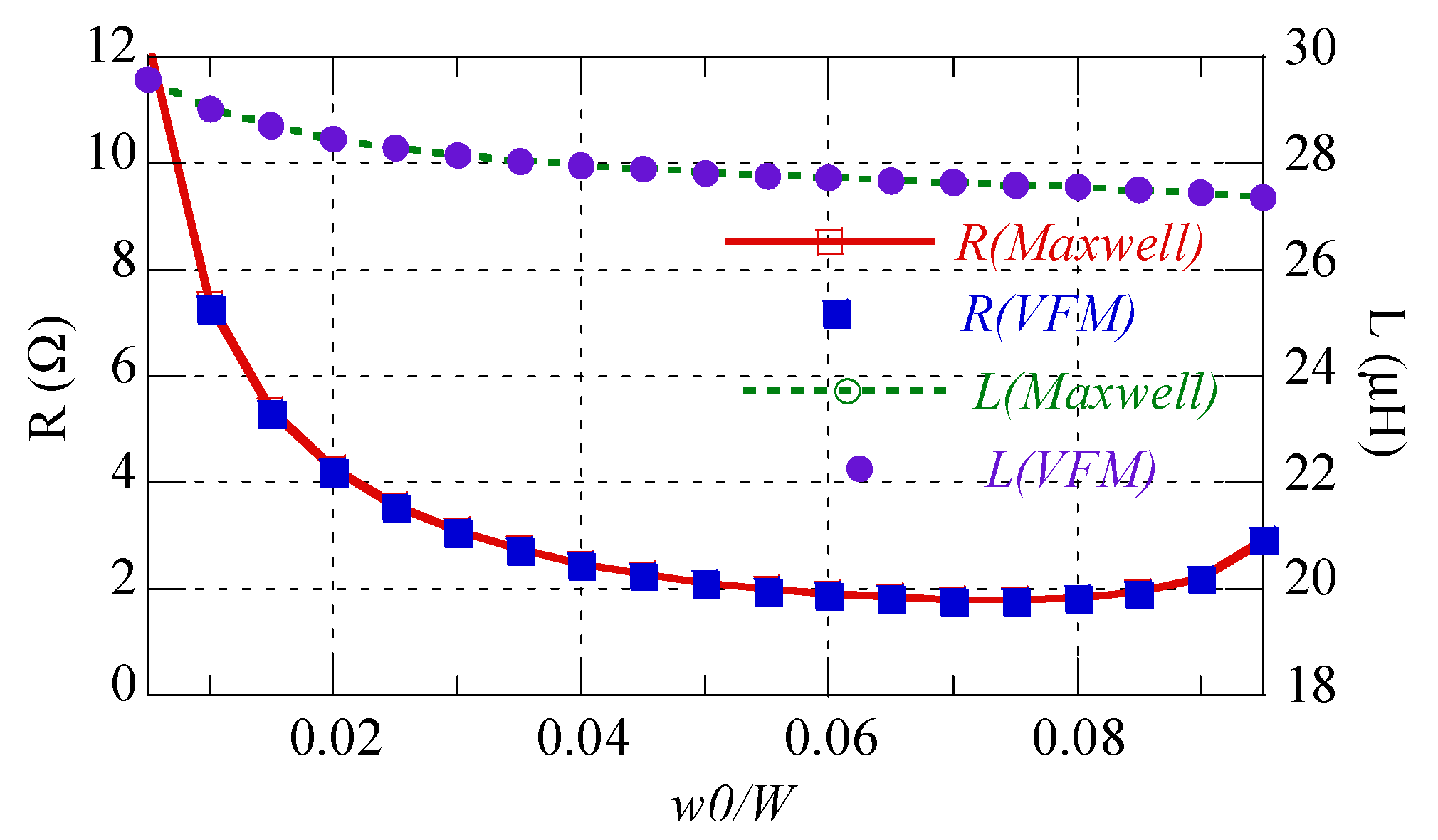
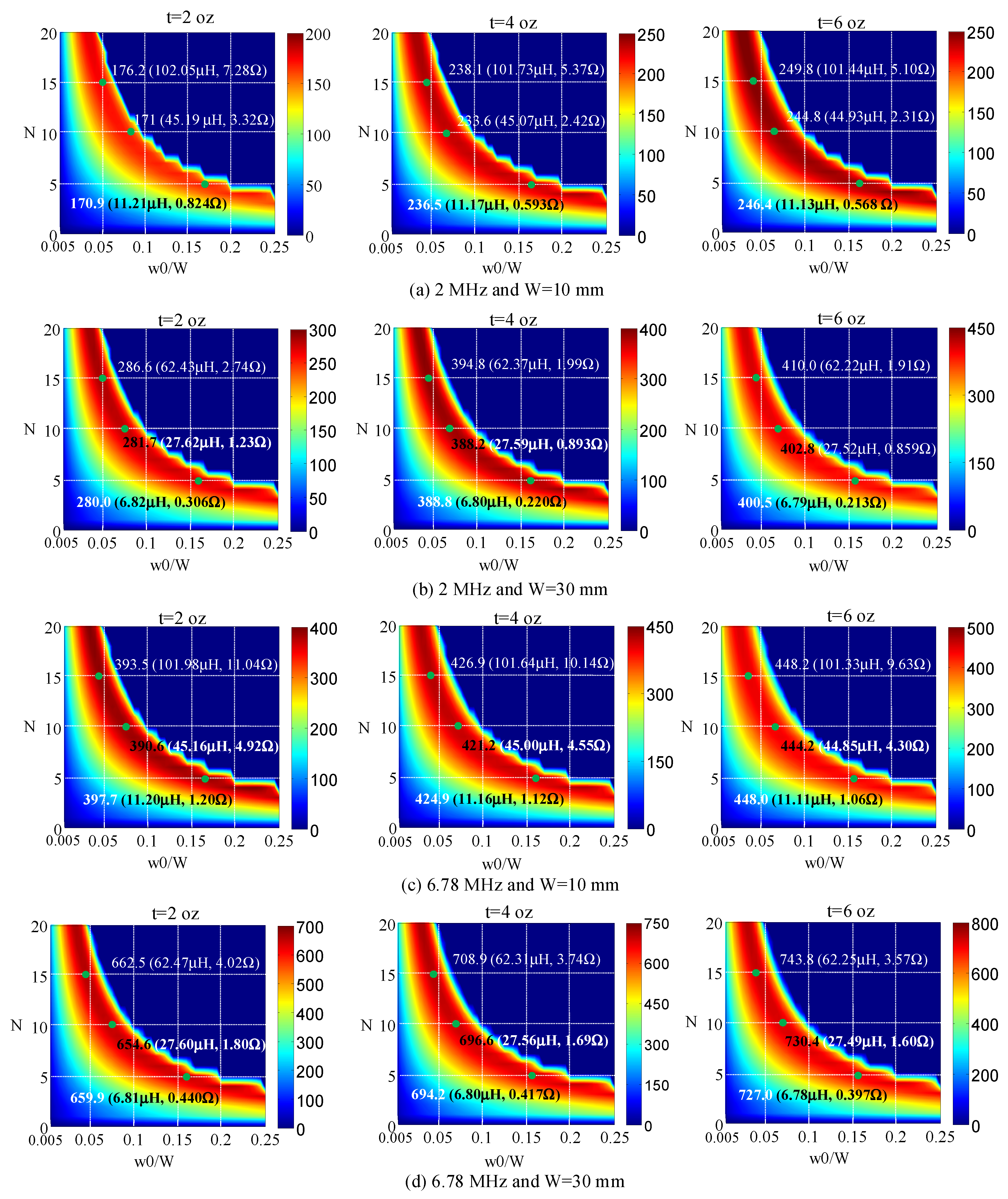
2.3. Calculation Results and Analysis

A coil’s Q-factor is defined as ωL/R, where L and R indicate the coil’s self-inductance and ohmic resistance (or ohmic losses), respectively. As the Q-factor is related to efficiency in a WPT system [18], designing a coil with a higher Q-factor is very important.
Using the calculation formulation from (1) to (7) explained in the previous section, the resistance and self-inductance of a printed spiral coil according to w0/W and N are calculated for frequencies of 2 MHz and 6.78 MHz; metal thicknesses of t = 1 oz, 2 oz, 4 oz, and 6 oz; total pattern widths (W) of 10 mm and 30 mm; and Rout of 100 mm. The Q-factors for these cases were obtained using the calculated self-inductances and resistances.
First, the proposed calculation method was verified through simulation using ANSYS Maxwell. In Figure 4, the calculation and simulation are compared for W = 30 mm, t = 2 oz, f = 6.78 MHz, and N = 10. The maximum differences between the two methods for resistance and self-inductance are 1.27% and 0.0062%, respectively. Specifically, the calculations of resistance and self-inductance were shown to be consistent with the calculations of simulations, according to w0/W. In addition, note that the lowest resistance existed near w0/W = 0.075. This was because when w0/W < 0.075, skin resistance (Rskin) increased and proximity resistance (Rprox) increased rapidly as the gap between two neighboring patterns (g) was reduced when w0/W > 0.075. To explain this, the proximity factor (Gp) was obtained using the average resistance (Ravg) and skin resistance (Rskin) [22], as follows:
R a v g = R s k i n + R p r o x = R s k i n ( 1 + R p r o x / R s k i n ) = R s k i n ( 1 + G p )   ( Ω / m )
where
G p = R a v g / R s k i n 1 .
Ravg indicates the average ohmic resistance of a pattern loop per unit length obtained at approximately W = 30 mm, as follows:
R a v g = 1 N R 2 π ( R o u t 15 ) / 1000 ( Ω / m )
where R is the total ohmic resistance calculated using (7) and N = 10. In Figure 5, normalized Rskin (Rnorm) is the skin resistance normalized for w0/W = 0.005 and Gp is the proximity factor. As shown in Figure 5, the skin resistance increased for w0/W < 0.075, while for w0/W > 0.075, Gp increased rapidly while the skin resistance decreased gradually. Therefore, the lowest resistance occurred near w0/W = 0.075.
In Figure 6, the calculated Q-factors are displayed according to 0.005 ≤ w0/W ≤ 0.25 and 2 ≤ N ≤ 20 at frequencies of 2 MHz and 6.78 MHz; metal thicknesses of 2 oz, 4 oz, and 6 oz; and total pattern widths of 10 mm and 30 mm. Additionally, for explanatory purposes, the resistances, self-inductances, and Q-factors are indicated for N = 5, 10, and 15. The dark blue color in the figure indicates that a coil cannot be produced.
As Figure 6 shows, an optimal w0/W for the maximum Q-factor can be found for each turn number in all cases. Note as well that the optimal w0/W was similar for each turn number in all cases, although the Q-factor increased with a thicker pattern, higher frequency, and wider total pattern for the same turn number. Furthermore, the optimal w0/W for the maximum Q-factors with the same frequency and pattern width was found to change slightly according to t.
Note that self-inductances were similar with the same turn number, total pattern width, and pattern width—regardless of frequency and thickness—while the ohmic resistances changed according to turn number, total pattern width, pattern width, frequency, and metal thickness.
According to the turn numbers, the maximum Q-factor changed little in all cases. This finding indicates that a turn number can be derived for self-inductance, which is necessary for a WPT system, and an optimal w0/W can then be obtained for the maximum Q-factor and maximum coupling efficiency.
As Figure 6 indicates, as a pattern thickened, the maximum Q-factor can be improved at the same frequency and W, as the self-inductance remained nearly the same while the ohmic resistance decreased. Practically, however, fabrication costs will increase for patterns thicker than 4 oz. The maximum Q-factor can also be improved with a higher frequency, because self-inductance changed very little while ohmic resistance grew slightly.
Figure 6a also shows that the ohmic resistance certainly decreased when the metal thickness changed from 2 oz to 4 oz for the same turn number and optimal w0/W, while it decreased slightly when the metal thickness changed from 4 oz to 6 oz. Figure 6c shows that the ohmic resistance decreased slightly when the metal thickness changed from 2 oz to 4 oz for the same turn number and optimal w0/W, while it rarely decreased when the metal thickness changed from 4 oz to 6 oz. Therefore, an improvement in ohmic resistance could not be obtained effectively when the metal thickness exceeded 4 oz at 2 MHz or 2 oz at 6.78 MHz. This finding indicates that a metal thickness of 4 oz at 2 MHz or 2 oz at 6.78 MHz could be used for optimal coil design.
Comparisons between Figure 6a,c or Figure 6b,d reveal that ohmic resistance increased at a higher frequency while self-inductance remained nearly the same for the same total pattern width, turn number, and w0/W. The reason for this finding is that skin resistance decreased at a lower frequency because the skin depth was greater.

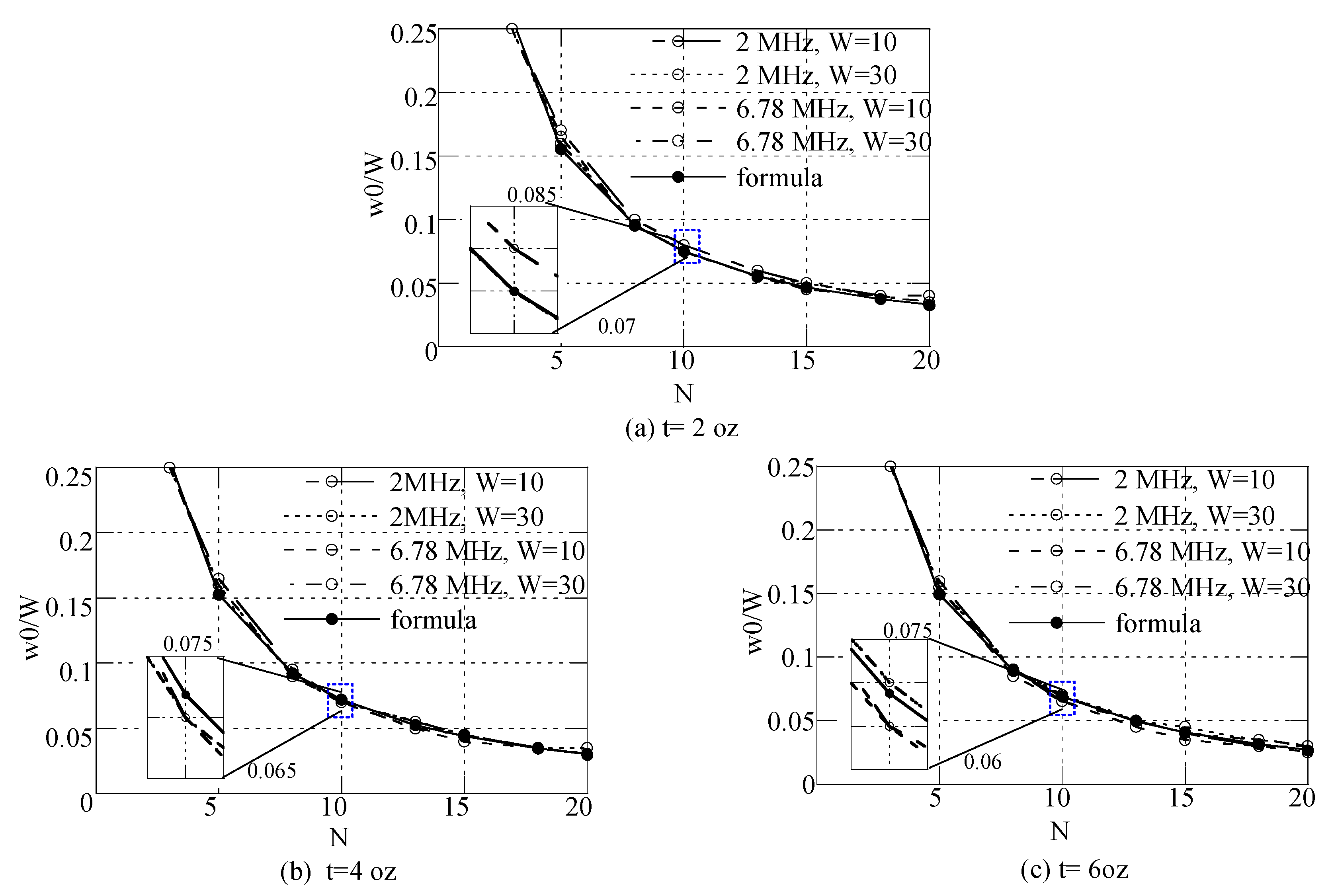
2.4. Deriving a Formula to Ensure the Maximum Q-Factor and Comparing Formulas and Calculations

As Figure 6 shows, the optimal w0/W for a given turn number was similar across all cases. Figure 7 indicates the optimal w0/W for the maximum Q-factor according to a given turn number at frequencies of 2 MHz and 6.78 MHz and pattern widths (W) of 10 mm and 30 mm, based on the calculation results presented in Figure 6. For metal thicknesses (t) of 2 oz, 4 oz, and 6 oz, the following formula was derived using curve fitting:
w 0 W = 0.00156 × t ( oz ) + 0.754185 × N 0.9263 0.01122 , N 3 .
Using (11), an optimal relationship of w0/W for the maximum Q-factor can be determined with a given metal thickness and turn number. For the total pattern width, each pattern’s width and the gap between neighboring patterns were also determined. Note that the formula includes the effect of metal thickness. In Figure 7, the calculation results of the proposed formula are compared for t = 2 oz, 4 oz, and 6 oz. Note that, with thicker patterns, the optimal w0/W decreased slightly for N ≥ 5. The formula’s results are shown consistent with the calculation results in Figure 6.
Note that the formula is effective in the MHz frequency range with total pattern widths less than about Rout/2 in cases where the proximity effect by a reverse current can be ignored [19].

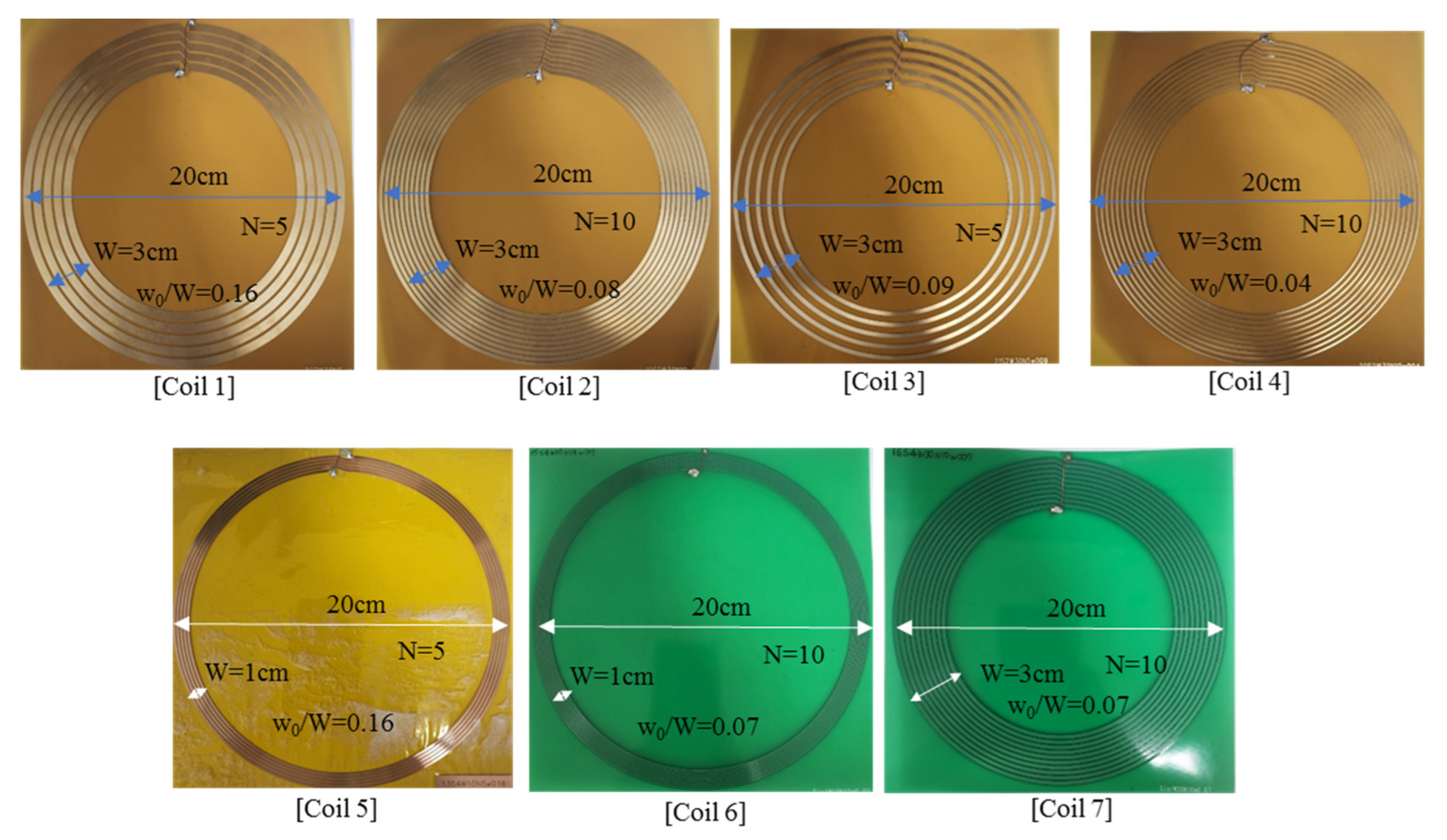
3. Fabrication and Comparisons between Measurements and Calculations

To verify the paper’s calculations, some optimized and non-optimized coils were fabricated. Figure 8 presents these fabricated coils. Table 1 displays the specifications of the fabricated coils, such as t, W, w0/W, and N. Coils 1, 2, 3, and 4 were produced using flexible PCB, while coils 5 and 6 were produced using FR4. Coils 1 and 2 were optimized, while coils 3 and 4 were not. The Agilent E5072A network analyzer was used to obtain measurements.
In Table 1, the Q-factors measured at 2 MHz are compared with corresponding calculations. First, the self-inductance measurements were consistent with the corresponding calculations, while the ohmic resistance measurements were slightly higher than the corresponding calculations. Therefore, the measured Q-factors were slightly lower than the calculated Q-factors. The reason for this difference was that the fabrication errors and equivalent series resistances (ESRs) for lumped capacitors at a resonance of 2 MHz can slightly increase the total ohmic resistance. That is, in fabrication, coil patterns were not etched precisely and the coil dimension may have been slightly changed. Small dielectric loss was also added. Additionally, lumped capacitors at a resonance of 2 MHz were used, and the ESR of the capacitors was added. To reduce the ESR, the resonant capacitors were loaded in parallel. Coils 3 and 4 were not optimized for maximum Q-factors. Compared with coils 1 and 2, coils 3 and 4 had lower Q-factors, increased ohmic resistance, and similar self-inductance.
For comparison between coils 2 and coil 7, the Q-factor for the metal pattern of 4 oz was higher than that for 2 oz and the ohmic resistance was lower, while the self-inductances of the two coils were similar. From the measurement of coils 1 and 5, the optimal w0/W for the same turn number was the same, and for coils 2, 6, and 7, the optimal w0/W for the same turn number was similar, but with different W and metal thicknesses.
The maximum coupling efficiencies, η, were compared between the two coils with the highest Q-factors. Compared with the optimal coils, these efficiencies were calculated as follows:
η = F o M 2 1 + F o M 2 + 1 2 = 1 + F o M 2 1 1 + F o M 2 + 1   with   F o M = ω M 12 R 1 · R 2 .
where R1 and R2 indicate the resistances of the Tx and Rx coils, respectively; M12 represents the mutual inductance between Tx and Rx coils; and FoM indicates the figure of merit of the MR-WPT system.
Table 2 presents the maximum coupling efficiency according to the distance between the Tx and Rx coils calculated with Equation (12). Mutual inductances were measured using the Agilent E5072A network analyzer, and measured resistances were used to determine the FoM. In Table 2, the maximum coupling efficiency between two coils is displayed at 15 cm, 30 cm, and 45 cm. Note that, as the turn number increased, the mutual inductance for two coils of 10 turns increased, but the efficiency and FoM remained similar compared with Case 1 of coils 1 and 2. The reason for this finding was that ohmic resistance also increased as the turn number increased. Therefore, an optimal printed spiral coil to target a specific self-inductance or turn number could be designed for a given total pattern width and metal thickness, and the coupling efficiency will be similar across such optimized coils, regardless of their turn number.
Finally, this work is compared with the previous works in Table 3. As shown, an optimal design formula for the maximum Q-factor is provided in this paper. The formula can be applied for various metal thicknesses in the MHz frequency range.

4. Conclusions

In this paper, an optimal design formula to ensure the maximum Q-factor of a printed spiral coil is provided for MR-WPT applications in the MHz frequency range. Accordingly, the ohmic resistance, self-inductance, and Q-factors of the printed spiral coils were calculated according to 0.005 ≤ w0/W ≤ 0.25 and 2 ≤ N ≤ 20 at frequencies of 2 MHz and 6.78 MHz, metal thicknesses of 2 oz, 4 oz, and 6 oz, and total pattern widths of 10 mm and 30 mm. An optimal w0/W to ensure the maximum Q-factor was found to be determinable for each turn number. Moreover, the optimal w0/W was found to be similar for each turn number in all cases, although the Q-factor was found to increase with thicker patterns, higher frequencies, and wider total pattern widths for the same turn number. With thicker patterns, the optimal w0/W was found to decrease slightly for N ≥ 5, regardless of frequencies. Finally, an optimal design formula was provided for a single-layer printed spiral coil to ensure its maximum Q-factor in the MHz frequency range. This formula can also be used to design an optimal printed spiral coil when a specific self-inductance is required.

Author Contributions

Conceptualization, Y.-J.P.; methodology, Y.-J.P.; validation, J.-E.K. and S.-H.L.; formal analysis, Y.-J.P.; investigation, J.-E.K. and K.-H.C.; data curation, J.-E.K. and S.-H.L.; writing—original draft preparation and writing—review and editing, Y.-J.P.; visualization, Y.-J.P.; supervision, Y.-J.P.; project administration, Y.-J.P.; funding acquisition, Y.-J.P. All authors have read and agreed to the published version of the manuscript.

Funding

This research was funded by a National Research Council of Science and Technology (NST) grant from the Korea government (MSIT), grant number CAP21051-100, and the KERI Primary research program of MSIT/NST, grant number 22A01054.

Institutional Review Board Statement

Not applicable.

Informed Consent Statement

Not applicable.

Data Availability Statement

Not applicable.

Conflicts of Interest

The authors declare no conflict of interest.

References

  1. Lammeraner, J.; Stafl, M. Eddy Currents; Iliffe Books: London, UK, 1966. [Google Scholar]
  2. Won, S.M.; Song, E.; Reeder, E.T.; Rogers, J.A. Emerging modalities and implantable technologies for neuromodulation. Cell 2020, 181, 115–135. [Google Scholar] [CrossRef] [PubMed]
  3. Won, S.M.; Cai, L.; Gutruf, P.; Rogers, J.A. Wireless and battery-free technology for neuroengineering. Nat. Biomed. Eng. 2021, 1–19. [Google Scholar] [CrossRef] [PubMed]
  4. Kim, C.Y.; Ku, M.J.; Qazi, R.; Nam, H.J.; Park, J.W.; Nam, K.S.; Oh, S.; Kang, I.; Jang, J.-H.; Kim, W.Y.; et al. Soft subdermal implant capable of wireless battery charging and programmable controls for applications in optogenetics. Nat. Commun. 2021, 12, 535. [Google Scholar] [CrossRef] [PubMed]
  5. Zhu, J.Q.; Ban, Y.L.; Zhang, Y.; Yan, Z.; Xu, R.M.; Mi, C.C. Metal-rim-connected inductive coupler for smartwatch applications. IET Power Electron. 2020, 13, 3428–3434. [Google Scholar] [CrossRef]
  6. Park, Y.J.; Kim, J.E.; Na, K.M.; Yang, K.D.; Cho, K.H. Optimization and analysis of multilayer planar spiral coils for the application of magnetic resonance wireless power transfer to wearable devices. Energies 2021, 14, 5113. [Google Scholar] [CrossRef]
  7. Houran, M.A.; Yang, X.; Chen, W. Magnetically coupled resonance WPT: Review of compensation topologies, resonator structures with misalignment, and EMI diagnostics. Electronics 2018, 7, 296. [Google Scholar] [CrossRef] [Green Version]
  8. Bao, K.; Zekios, C.L.; Georgakopoulos, S.V. A wearable WPT system on flexible substrates. IEEE Antennas Wirel. Propag. Lett. 2019, 18, 931–935. [Google Scholar] [CrossRef]
  9. Kim, J.; Banks, A.; Xie, Z.; Heo, S.Y.; Gutruf, P.; Lee, J.W.; Xu, S.; Jang, K.I.; Liu, F.; Brown, G.; et al. Miniaturized flexible electronic systems with wireless power and near-field communication capabilities. Adv. Funct. Mater. 2015, 25, 4761–4767. [Google Scholar] [CrossRef]
  10. Zhou, W.; Wu, P.; Mu, W.C.; Yu, W.; Huang, S.Y. Compact broadband planar resonator with a viaed double spiral for robust wireless power transfer. IEEE J. Electromagn. RF Microw. Med. Biol. 2021, 5, 329–339. [Google Scholar] [CrossRef]
  11. Kim, J.; Cha, C.; Oh, J.; Hong, Y. New design topology of high-Q factor printed base antenna having unequal width and pitch used for near-field wireless power transmission. IEEE J. Emerg. Sel. Top. Power Electron. 2022, 10, 984–996. [Google Scholar] [CrossRef]
  12. Jolani, F.; Yu, Y.; Chen, Z. A planar magnetically coupled resonant wireless power transfer system using printed spiral coils. IEEE Antennas Wirel. Propag. Lett. 2014, 13, 1648–1651. [Google Scholar] [CrossRef]
  13. Li, J.; Lin, J.-K.; Song, X.; Yan, S.; Xu, K.-D.; Zhang, X.Y. Efficiency-enhanced wireless power transfer based on multiple coupling paths. IEEE Microw. Wirel. Compon. Lett. 2022, 32, 444–447. [Google Scholar] [CrossRef]
  14. Kim, D.-H.; Park, Y.-J. Calculation of the inductance and AC resistance of planar rectangular coils. Electron. Lett. 2016, 52, 1321–1323. [Google Scholar] [CrossRef]
  15. Lope, I.; Carretero, C.; Acero, J.; Alonso, R.; Burdio, J.M. AC power losses model for planar windings with rectangular cross-sectional conductors. IEEE Trans. Pow. Electron. 2014, 29, 23–28. [Google Scholar] [CrossRef]
  16. Nguyen, M.H.; Blanchette, H.F. Optimizing AC resistance of solid PCB winding. Electronics 2020, 9, 875. [Google Scholar] [CrossRef]
  17. Jow, U.-M.; Ghovanloo, M. Design and optimization of printed spiral coils for efficient transcutaneous inductive power transmission. IEEE Trans. Biomed. Circuits Syst. 2007, 1, 193–202. [Google Scholar] [CrossRef]
  18. Kurs, A.; Karalis, A.; Moffatt, R.; Joannopoulos, J.D.; Fisher, P.; Soljacic, M. Wireless power transfer via strongly coupled magnetic resonances. Science 2007, 317, 83–86. [Google Scholar] [CrossRef] [Green Version]
  19. Kim, D.-H.; Kim, J.; Park, Y.-J. Optimization and design of small circular coils in a magnetically coupled wireless power transfer system in the megahertz frequency. IEEE Trans. Microw. Theory Tech. 2016, 64, 1–12. [Google Scholar] [CrossRef]
  20. Zierhofer, C.M.; Hochmeair, E.S. Geometric approach for coupling enhancement of magnetically coupled coils. IEEE Trans. Biomed. Eng. 1996, 43, 708–714. [Google Scholar] [CrossRef]
  21. Good, R.H. Elliptic integrals, the forgotten functions. Eur. J. Phys. 2001, 22, 119–126. [Google Scholar] [CrossRef]
  22. Kim, J.; Park, Y.-J. Approximate closed-form formula for calculating ohmic resistance in coils of parallel round wires with unequal pitches. IEEE Trans. Ind. Electron. 2015, 62, 3482–3489. [Google Scholar]
Figure 1. Illustrations of (a) a printed spiral coil, (b) a concentric multi-loops coil equivalent to the spiral coil, and (c) their cross-sections.
Sensors 22 07761 g001
Figure 2. (a) Printed concentric circular coils of N loops and cross-section of the kth and mth loops with discretization in the square. (b) The fth and gth circular filament loops of the kth and mth circular loops and their equivalent model.
Sensors 22 07761 g002
Figure 3. An equivalent circuit of a printed spiral coil with N turns.
Sensors 22 07761 g003
Figure 4. Comparison between the calculations and simulations of ohmic resistance and self-inductance for W = 30 mm, t = 2 oz, f = 6.78 MHz, and N = 10.
Sensors 22 07761 g004
Figure 5. Normalized skin resistance (Rnorm) for w0/W = 0.005 and proximity factor, Gp, according to w0/W.
Sensors 22 07761 g005
Figure 6. Calculated Q-factors according to 2 ≤ N ≤ 20 and 0.005 ≤ w0/W ≤ 0.25 for frequencies of 2 MHz and 6.78 MHz, W = 10 mm and 30 mm, and pattern thickness of 2 oz, 4 oz, and 6 oz.
Sensors 22 07761 g006
Figure 7. The formula’s optimal w0/W, calculated using (11), and comparison between the calculations and formula results according to turn number N for the maximum Q-factor at frequencies of 2 MHz and 6.78 MHz, total pattern widths (W) of 10 mm and 30 mm, and metal thicknesses (t) of (a) 2 oz, (b) 4 oz, and (c) 6 oz.
Sensors 22 07761 g007
Figure 8. Photographs of coils optimized (coils 1, 2, 5, 6, and 7) for maximum Q-factor and fabricated coils that were not optimized (coils 3 and 4) to be compared with coils 1 and 2, respectively.
Sensors 22 07761 g008
Table 1. Specifications of the fabricated coils, and comparison of the Q-factor at 2 MHz and ohmic losses of the coils between the measurement and calculation.
t(oz)Nw0/WCalculationMeasurement
R (Ω)L (μH)Q-FactorR (Ω)L (μH)Q-Factor
Coil 1250.16 (W = 30)0.30586.8153280.00.3446.92252.77
Coil 22100.08 (W = 30)1.24927.58277.461.59127.761219.27
Coil 3250.09 (W = 30)0.4266.98205.690.5847.354158.24
Coil 42100.04 (W = 30)1.71827.99204.752.28628.348155.77
Coil 5450.16 (W = 10)0.59511.17236.150.75111.275188.6
Coil 64100.07 (W = 10)2.424745.07233.63.06745.34185.73
Coil 74100.07 (W = 30)0.89327.59388.191.09627.7317.61
Table 2. Maximum coupling efficiency, mutual inductance, and FoM according to the distance between Tx and Rx coils for two cases. Case 1 is coil 5 (Tx) and coil 6 (Rx). Case 2 is coil 6 (Tx) and coil 6 (Rx).
Distance between Tx and RxCase 1 (Coil 5 (Tx) and Coil 6 (Rx))Case 2 (Coil 2 (Tx) and Coil 2 (Rx))
M (μH)FoMEfficiency (%)M (μH)FoMEfficiency (%)
15 cm1.0899.01780.12.1248.70279.5
30 cm0.2171.79734.50.4751.94637.2
45 cm0.1000.82813.00.2310.94618.8
Table 3. Comparison between previous studies and this work.
[14][15][16][17]This Work
Verified frequencyUp to 1 MHzUp to 1 MhzUp to 6.78 MHzUp to 10 MHzUp to 6.78 MHz
Calculated metal thickness1 oz, 2 oz1 oz, 2 oz~4 oz1 oz2 oz, 4 oz, 6 oz
Coil shapeCircularCircularRectangularRectangularCircular
Optimal design formulaNoNoNoNoYes
Publisher’s Note: MDPI stays neutral with regard to jurisdictional claims in published maps and institutional affiliations.

