

Tracking Efficiency Improvement According to Incident Beam Size in QPD-Based PAT System for Common Path-Based Full-Duplex FSO Terminals

 ,
,
Abstract
:1. Introduction
2. Experimental Details
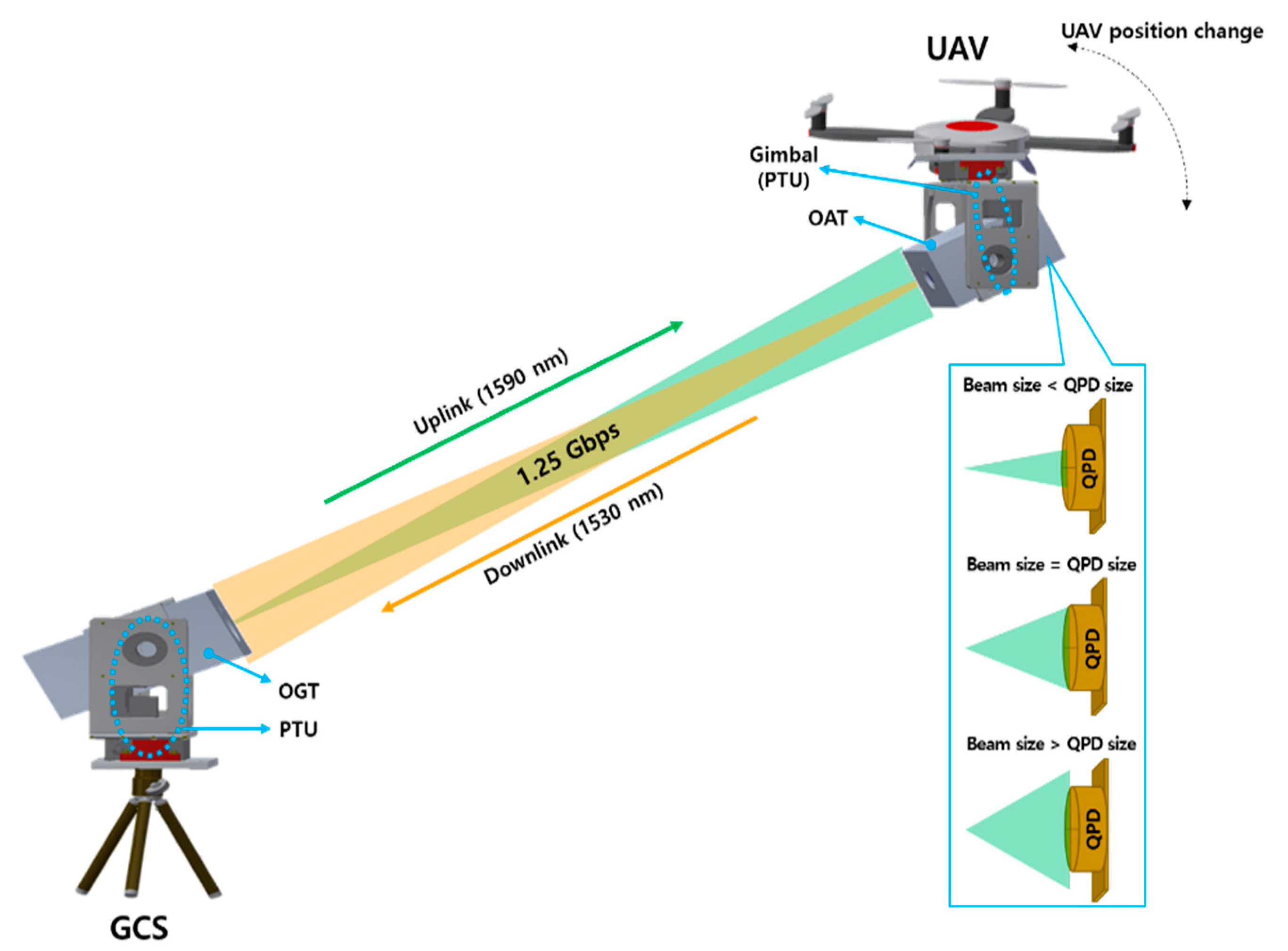
2.1. System Concept
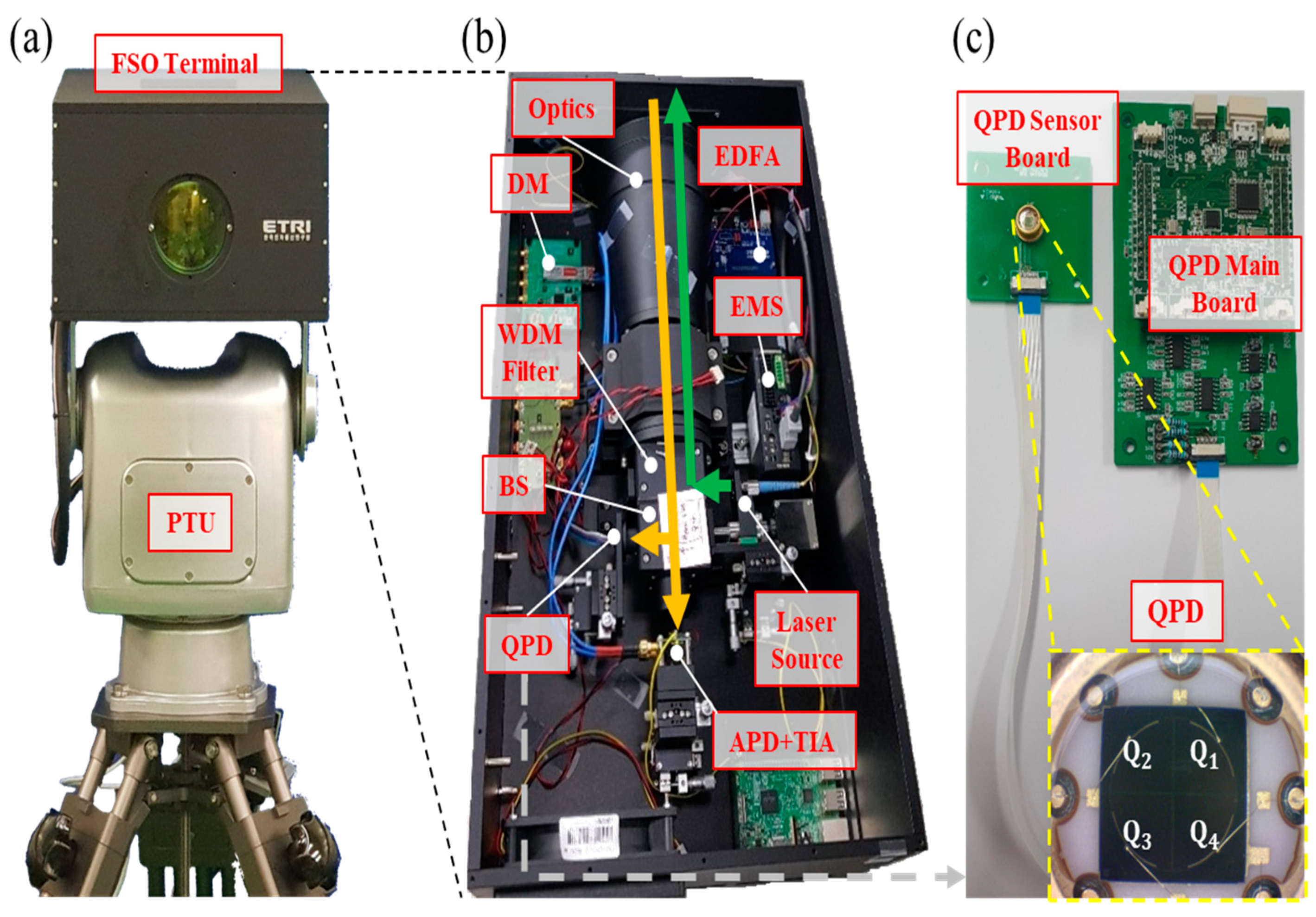
2.2. System Design
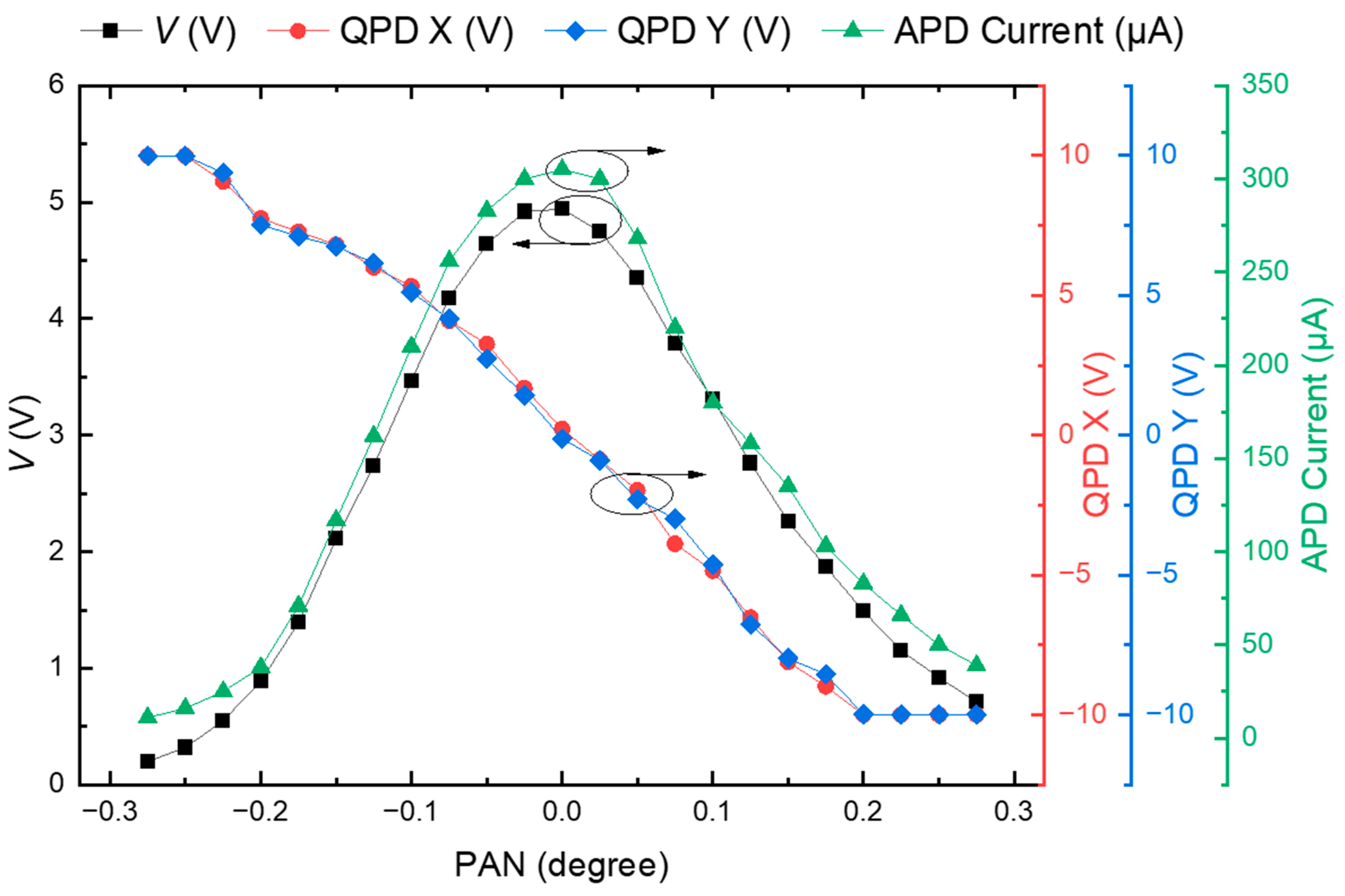
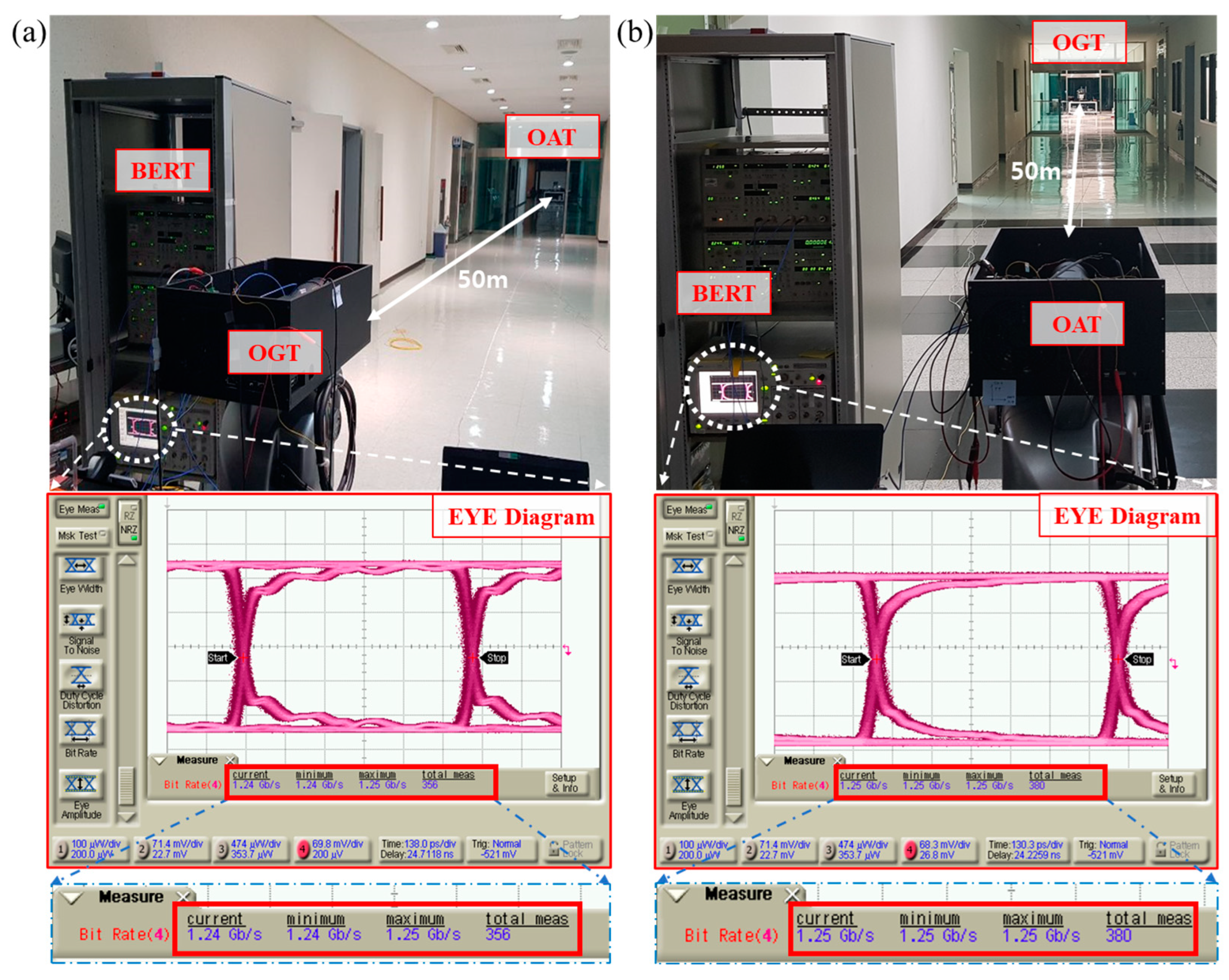
3. Experimental Results
4. Conclusions
Author Contributions
Funding
Institutional Review Board Statement
Informed Consent Statement
Data Availability Statement
Conflicts of Interest
References
- Alzenad, M.; Shakir, M.Z.; Yanikomeroglu, H.; Alouini, M.S. FSO-based vertical backhaul/fronthaul framework for 5G+ wireless networks. IEEE Commun. Mag. 2018, 56, 218–224. [Google Scholar] [CrossRef] [Green Version]
- Fawaz, W.; Abou-Rjeily, C.; Assi, C. UAV-aided cooperation for FSO communication systems. IEEE Commun. Mag. 2018, 56, 70–75. [Google Scholar] [CrossRef]
- Dong, Y.; Hassan, M.Z.; Cheng, J.; Hossain, M.J.; Leung, V.C. An edge computing empowered radio access network with UAV-mounted FSO fronthaul and backhaul: Key challenges and approaches. IEEE Wirel. Commun. 2018, 25, 154–160. [Google Scholar] [CrossRef] [Green Version]
- Lee, J.H.; Park, K.H.; Ko, Y.C.; Alouini, M.S. A UAV-mounted free space optical communication: Trajectory optimization for flight time. IEEE Trans. Wirel. Commun. 2019, 19, 1610–1621. [Google Scholar] [CrossRef]
- Ding, J.; Mei, H.; I, C.L.; Zhang, H.; Liu, W. Frontier progress of unmanned aerial vehicles optical wireless technologies. Sensors 2020, 20, 5476. [Google Scholar] [CrossRef] [PubMed]
- Al-Gailani, S.A.; Salleh, M.F.M.; Salem, A.A.; Shaddad, R.Q.; Sheikh, U.U.; Algeelani, N.A.; Almohamad, T.A. A survey of free space optics (FSO) communication systems, links, and networks. IEEE Access 2020, 9, 7353–7373. [Google Scholar] [CrossRef]
- Jahid, A.; Alsharif, M.H.; Hall, T.J. A contemporary survey on free space optical communication: Potentials, technical challenges, recent advances and research direction. J. Netw. Comput. Appl. 2022, 200, 103311. [Google Scholar] [CrossRef]
- Petkovic, M.I.; Djordjevic, G.T. Impact of temporary link blockage on ergodic capacity of FSO system. ETRI J. 2018, 40, 330–336. [Google Scholar] [CrossRef]
- Seo, S.; Ko, D.E.; Chung, J.M. Combined time bound optimization of control, communication, and data processing for FSO-based 6G UAV aerial networks. ETRI J. 2020, 42, 700–711. [Google Scholar] [CrossRef]
- Wang, J.Y.; Ma, Y.; Lu, R.R.; Wang, J.B.; Lin, M.; Cheng, J. Hovering UAV-based FSO communications: Channel modelling, performance analysis, and parameter optimization. IEEE J. Sel. Areas Commun. 2021, 39, 2946–2959. [Google Scholar] [CrossRef]
- Yang, H.; Wang, B.; Yao, Q.; Yu, A.; Zhang, J. Efficient hybrid multi-faults location based on Hopefield neural network in 5G coexisting radio and optical wireless networks. IEEE. Trans. Cogn. Commun. Netw. 2019, 5, 1218–1228. [Google Scholar] [CrossRef]
- Yang, H.; Zhang, J.; Ji, Y.; Lee, Y. C-RoFN: Multi-stratum resources optimization for cloud-based radio over optical fiber networks. IEEE Commun. Mag. 2016, 54, 118–125. [Google Scholar] [CrossRef]
- Kong, H.; Lin, M.; Zhu, W.-P.; Amindavar, H.; Alouini, M.-S. Multiuser scheduling for asymmetric FSO/RF links in satellite-UAV-terrestrial networks. IEEE Wirel. Commun. Lett. 2020, 9, 1235–1239. [Google Scholar] [CrossRef]
- Sharma, S.R.S.; Vishwakarma, N.; Madhukumar, A. HAPS-based relaying for integrated space-air-ground networks with hybrid FSO/RF communication: A performance analysis. IEEE Trans. Aerosp. Electron. Syst. 2021, 57, 1581–1599. [Google Scholar]
- Kaymak, Y.; Rojas-Cessa, R.; Feng, J.; Ansari, N.; Zhou, M.; Zhang, T. A survey on acquisition, tracking, and pointing mechanisms for mobile free-space optical communications. IEEE Commun. Surv. Tuts. 2018, 20, 1104–1123. [Google Scholar] [CrossRef]
- Quintana, C.; Erry, G.; Gomez, A.; Thueux, Y.; Faulkner, G.E.; O’Brien, D.C. Design of a holographic tracking module for long-range retroreflector free-space systems. Appl. Opt. 2016, 55, 7173–7178. [Google Scholar] [CrossRef]
- Quintana, C.; Wang, Q.; Jakonis, D.; Piao, X.; Erry, G.; Platt, D.; Thueux, Y.; Gomez, A.; Faulkner, G.; Chun, H.; et al. High speed electro-absorption modulator for long range retroreflective free space optics. IEEE Photon. Technol. Lett. 2017, 29, 707–710. [Google Scholar] [CrossRef]
- Quintana, C.; Wang, Q.; Jakonis, D.; Oberg, O.; Erry, G.; Platt, D.; Thueux, Y.; Faulkner, G.; Chun, H.; Gomez, A.; et al. A high speed retro-reflective free space optics links with UAV. J. Lightw. Technol. 2021, 39, 5699–5705. [Google Scholar] [CrossRef]
- Brandl, P.; Schidl, S.; Polzer, A.; Gaberl, W.; Zimmermann, H. Optical wireless communication with adaptive focus and MEMS-based beam steering. IEEE Photon. Technol. Lett. 2013, 25, 1428–1431. [Google Scholar] [CrossRef]
- Lahari, S.A.; Raj, A.; Soumya, S. Control of fast steering mirror for accurate beam positioning in FSO communication system. In Proceedings of the 2021 International Conference on System, Computation, Automation, and Networking (ICSCAN), Puducherry, India, 30–31 July 2021; pp. 1–6. [Google Scholar]
- Mai, V.; Kim, H. Beaconless angle-of-arrival tracking with improved receiver sensitivity and tracking precision for free-space optical communications. Opt. Commun. 2022, 527, 128963. [Google Scholar] [CrossRef]
- Ishola, F.; Cho, M. Experimental study on photodiode array sensor aided MEMS fine steering mirror control for laser communication platforms. IEEE Access 2021, 9, 100197–100207. [Google Scholar] [CrossRef]
- Lim, H.C.; Choi, C.S.; Sung, K.P.; Park, J.U.; Choi, M. Centroid error analysis of beacon tracking under atmospheric turbulence for optical communication links. Remote Sens. 2021, 13, 1931. [Google Scholar] [CrossRef]
- Moll, F.; Horwath, J.; Shrestha, A.; Brechtelsbauer, M.; Fuchs, C.; Navajas, L.A.M.; Souto, A.M.L.; González, D.D. Demonstration of high-rate laser communications from a fast airborne platform. IEEE J. Sel. Areas Commun. 2015, 33, 1985–1995. [Google Scholar] [CrossRef]
- Page, T.A.; Rabinovich, J.W.; Thomas, L.M.; Menas, A.; Ferraro, M.S.; Rabinovich, W.S.; Mahon, R.; Freeman, W.T. A system overview of a small form factor free space optical communiation prototype. In Proceedings of the Free-Space Laser Communication Technologies XXXII, San Francisco, CA, USA, 2 March 2020; pp. 141–147. [Google Scholar]
- Trinh, P.V.; Carrasco-Casado, A.; Okura, T.; Tsuji, H.; Kolev, D.R.; Shiratama, K.; Munemasa, Y.; Toyoshima, M. Experimental channel statistics of drone-to-ground retro-reflected fso links with fine-tracking systems. IEEE Access 2021, 9, 137148–137164. [Google Scholar] [CrossRef]
- Li, Q.; Xu, S.; Yu, J.; Yan, L.; Huang, Y. An improved method for the position detection of a quadrant detector for free space optical communication. Sensors 2019, 19, 175. [Google Scholar] [CrossRef] [PubMed] [Green Version]
- Wang, X.; Su, X.; Liu, G.; Han, J.; Wang, K.; Zhu, W. A method for improving the detection accuracy of the spot position of the four-quadrant detector in a free space optical communication system. Sensors 2020, 20, 7164. [Google Scholar] [CrossRef]
- Wang, Z.; Zhang, Z.; Zou, K.; Meng, Y.; Hu, X. Silicon four-quadrant photodetector working at the 1550-nm telecommunication wavelength. Opt. Lett. 2022, 47, 4048–4051. [Google Scholar] [CrossRef]
- Safi, H.; Dargahi, A.; Cheng, J. Beam tracking for UAV-assisted FSO links with a four-quadrant detector. IEEE Commun. Lett. 2021, 5, 3908–3912. [Google Scholar] [CrossRef]
- Manojlovic, L.M.; Barbaric, Z.P. Optimization of optical receiver parameters for pulsed laser-tracking systems. IEEE Trans. Instrum. Meas. 2009, 58, 681–690. [Google Scholar] [CrossRef]
- Zhang, W.; Guo, W.; Zhang, C.; Zhao, S. An improved method for spot position detection of a laser tracking and positioning system based on a four-quadrant detector. Sensors 2019, 19, 4722. [Google Scholar] [CrossRef] [Green Version]
- Zhang, C.; Duan, F.; Fu, X.; Liu, W.; Su, Y.; Li, X. Research of intelligence segment-fitting algorithm for increasing the measurement accuracy of quadrant detector in straightness measuring system. Opt. Laser Technol. 2020, 125, 106062. [Google Scholar] [CrossRef]
- Wang, X.; Su, X.; Liu, G.; Han, J.; Zhu, W.; Liu, Z. Method to improvement the detection accuracy of quadrant detector based on neural network. IEEE Photon. Technol. Lett. 2021, 33, 1254–1257. [Google Scholar] [CrossRef]
- Qiu, Z.; Jia, W.; Ma, X.; Zou, B.; Lin, L. Neural-network-based method for improving measurement accuracy of four-quadrant detectors. Appl. Opt. 2022, 61, F9–F14. [Google Scholar] [CrossRef]
- Ng, T.W.; Foo, S.L.; Tan, H.Y. Gaussian laser beam diameter measurement using a quadrant photodiode. Rev. Sci. Instrum. 2005, 76, 065110. [Google Scholar] [CrossRef]
- Ng, T.W.; Tan, H.Y.; Foo, S.L. Small gaussian laser beam diameter measurement using a quadrant photodiode. Opt. Laser Technol. 2007, 39, 1098–1100. [Google Scholar] [CrossRef]
- Chen, M.; Yang, Y.; Jia, X.; Gao, H. Investigation of positioning algorithm and method for increasing the linear measurement range for four-quadrant detector. Optik 2013, 124, 6806–6809. [Google Scholar] [CrossRef]
- Falcón, R.E.C.; Escuela, A.M.; Sendra, J.S.; Santana, D.F. Subsampling techniques for gaussian laser beam radius estimation using a configurable quadrant photodiode (CQD). Opt. Laser Technol. 2019, 109, 412–417. [Google Scholar] [CrossRef]
- Park, S.; Yeo, C.I.; Heo, Y.S.; Ryu, J.H.; Kang, H.S.; Kim, S.C.; Jang, J.H. Common path-based mobile free-space optical terminal with adaptive beamforming function for Gbps out-of-band full-duplex connectivity to UAVs. Opt. Commun. 2021, 494, 127041. [Google Scholar] [CrossRef]
- Harada, R.; Shibata, N.; Kaneko, S.; Imai, T.; Kani, J.I.; Yoshida, T. Adaptive beam divergence for expanding range of link distance in FSO with moving nodes toward 6G. IEEE Photon. Technol. Lett. 2022, 34, 1061–1064. [Google Scholar] [CrossRef]


| Type of Data Transmission | Optical Path for Tx/Rx/Beacon | Link Rate (Gbps) | Beamforming (θdiv) | PAT Type | Number of Optical Components | Ref. |
|---|---|---|---|---|---|---|
| Simplex (UAV-Ground) | Separate | 0.5 | SLM 1 | Hybrid (MRR + FSM + QPD + Camera) | ≤19 (Ground) | [18] |
| Simplex (Airborne platform -TOGS) | Separate | 1.25 | Fixed (2.26 mrad) | Hybrid (FSM + Camera) | ≥23 (TOGS 2) | [24] |
| Full-duplex (UAV-Ground) | Separate | 1 | FSM | Hybrid (FSM + 5-cell detector) | ≤10 (Ground) | [25] |
| Simplex (UAV-Ground) | Share | - | - | Hybrid (FSM + Camera + QPD) | ≤12 (Ground) | [26] |
| Full-duplex (OAT-OGT) | Share | 1.25 | EMS (0~8.84 mrad) | QPD | ≤9 (OGT) | This work |
Publisher’s Note: MDPI stays neutral with regard to jurisdictional claims in published maps and institutional affiliations. |
© 2022 by the authors. Licensee MDPI, Basel, Switzerland. This article is an open access article distributed under the terms and conditions of the Creative Commons Attribution (CC BY) license (https://creativecommons.org/licenses/by/4.0/).
Share and Cite
Park, S.; Yeo, C.I.; Heo, Y.S.; Ryu, J.H.; Kang, H.S.; Lee, D.-S.; Jang, J.-H. Tracking Efficiency Improvement According to Incident Beam Size in QPD-Based PAT System for Common Path-Based Full-Duplex FSO Terminals. Sensors 2022, 22, 7770. https://doi.org/10.3390/s22207770
Park S, Yeo CI, Heo YS, Ryu JH, Kang HS, Lee D-S, Jang J-H. Tracking Efficiency Improvement According to Incident Beam Size in QPD-Based PAT System for Common Path-Based Full-Duplex FSO Terminals. Sensors. 2022; 22(20):7770. https://doi.org/10.3390/s22207770
Chicago/Turabian StylePark, Siwoong, Chan Il Yeo, Young Soon Heo, Ji Hyoung Ryu, Hyun Seo Kang, Dong-Seon Lee, and Jae-Hyung Jang. 2022. "Tracking Efficiency Improvement According to Incident Beam Size in QPD-Based PAT System for Common Path-Based Full-Duplex FSO Terminals" Sensors 22, no. 20: 7770. https://doi.org/10.3390/s22207770