Abstract
The measurement of yarn tension has a direct impact on the product quality and production efficiency in the textile manufacturing process, and the surface acoustic wave (SAW) yarn tension sensor is a good option for detecting the yarn tension. For SAW yarn tension sensors, sensitivity is an important indicator to assess their performance. In this paper, a new type of SAW yarn tension sensor based on a simply supported beam structure is studied to improve the sensitivity of the fixed beam SAW yarn tension sensor. The sensitivity analysis method based on elastic beam theory is proposed to illustrate the sensitivity optimization. According to the analysis results, the sensitivity of the SAW yarn tension sensor can be greatly improved by using a simply supported beam structure compared to the s fixed beam structure. Moreover, from the calibration experiment, the sensitivity of the simply supported beam SAW yarn tension sensor is 2.5 times higher than that of the fixed beam sensor.
1. Introduction
The measurement of yarn tension is very important in the textile manufacturing process, which directly affects the product quality, the production efficiency, and the subsequent processing [1,2,3,4]. Significantly, with the rapid development of SAW [5,6,7,8,9,10] devices, SAW sensors [11,12,13] are being used in a wide range of industries. Furthermore, the SAW yarn tension sensor studied in [14,15,16,17,18,19] is a good selection to adapt to today’s textile manufacturing; it has excellent characteristics, such as high stability, high sensitivity, fast response speed, strong anti-interference ability, small size, low cost, and so on [20].
A cantilever beam SAW yarn tension sensor is introduced in [21], and the reliability of the sensor is poor because of the cantilever beam, which is easy to break during the measuring process [22], and this is disadvantageous to the universality of the sensor in practical applications. A fixed beam SAW yarn tension sensor is discussed in [22], and it was concluded that the sensitivity of the fixed beam SAW yarn tension sensor in [22] is 12.996 kHz/N, which is much lower than that of the cantilever beam sensor. It is well known that the lower the sensitivity of the yarn tension sensor, the poorer the quality of the yarn and fabric product, and the lower the yield of the yarn and fabric product [15]. There is no doubt that the fixed beam sensor studied in [20,22] holds important value for the promotion of the SAW yarn tension sensor in practical applications. However, the improvement of the sensitivity of the fixed beam sensor is a key problem that needs to be solved urgently.
From [15,22], the size of the piezoelectric substrate and the position of the interdigital transducer (IDT) are key factors affecting the sensitivity of the SAW yarn tension sensor, which are determined based on the simulation results of the finite element method (FEM) [23,24]. It is obvious that the sensitivity analysis of the SAW yarn tension sensor is overly dependent on the complex simulation methods. There still lacks a simple and efficient analysis method for sensitivity optimization. For the fixed beam SAW yarn tension sensor, the sensitivity of the sensor can be improved by increasing the length of the piezoelectric substrate. However, in practical applications, the SAW yarn tension sensor generally needs to be installed in textile machinery with limited space, which makes it difficult to increase the size of the sensor to improve the sensitivity.
In this paper, the bending moment distribution analysis of a beam based on elastic theory is proposed as a theoretical analysis method for the sensitivity analysis of the SAW yarn tension sensor, which is simple and efficient compared with the simulation methods. Targeting the sensitivity enhancement of the fixed beam sensor, a new type of SAW yarn tension sensor based on the simply supported beam [25,26,27,28] structure is adopted in this paper. According to the analysis results, it can be concluded that the sensitivity of the SAW yarn tension sensor will be significantly improved when the structural form of the beam is changed from a fixed beam to a simply supported beam, without increasing the size of the SAW sensor. Moreover, the experimental verification based on test data is elaborated in this paper. By comparison, the sensitivity of the simply supported beam SAW yarn tension sensor studied in this paper is about 2.5 times that of the fixed beam sensor.
2. Principle Analysis
2.1. The Working Principle of SAW Yarn Tension Sensor
The structure diagram of the SAW sensor is shown in Figure 1, and Figure 2 shows the working principle of the SAW yarn tension sensor. From Figure 1, the IDTs are positioned on the upper surface of the piezoelectric substrate, a0 represents the width of the interdigital electrodes, when the yarn tension, F = 0, b0 represents the corresponding interdigital electrodes spacing, and a0 = b0. The relationship between the output frequency, f0 of the SAW oscillation (when the yarn tension, F = 0) and the SAW wavelength, λ0 is as follows:
where λ0 = 2 (a0 + b0) = 4b0; and v0 represents the SAW propagation speed when the yarn tension F = 0.
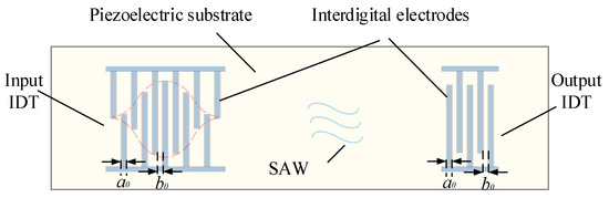
Figure 1.
Structure diagram of the SAW sensor.

Figure 2.
The working principle diagram of the SAW yarn tension sensor.
As can be seen from Figure 2, the yarn tension F loaded on the piezoelectric substrate causes bending deformation of the piezoelectric substrate. The change in the yarn tension F causes a change in the interdigital electrodes spacing, as well as in the propagation speed of the SAW [16]. From Equation (1), the output frequency of the SAW oscillation varies with the yarn tension, F. So, the measurement of yarn tension, F can be realized by detecting the frequency variation, Δf.
2.2. Sensitivity Analysis of SAW Yarn Tension Sensor Based on Elastic Beam Theory
For the SAW yarn tension sensor, the piezoelectric substrate is equivalent to a slender beam, and the yarn tension to be measured corresponds to a concentrated load, F, acting on the beam. From elastic beam theory, when F is loaded within the elastic range, the beam undergoes elastic deformation [29] under the action of bending moment M, as shown in Figure 3.
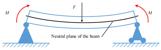
Figure 3.
Schematic diagram of elastic deformation of the beam.
From Figure 4a, a micro-segment of length dx is cut from the beam, shown in Figure 3, using two adjacent cross-sections. The deformation diagram of the micro-segment beam is shown in Figure 4b. Suppose that after the beam is bent (under the action of bending moment M), the two cross-sections remain in plane but are turned around their respective neutral planes by an angle dθ. In the coordinate system of Figure 4, the x-axis is along the axis of the beam and the y-axis is along the height of the cross-section. In Figure 4b, the length variation, Δdx, of the upper surface (height from the neutral plane is equal to h) of the micro-segment is as follows:
where h is equal to half the height of the beam, and the negative sign indicates the occurrence of the compression deformation.
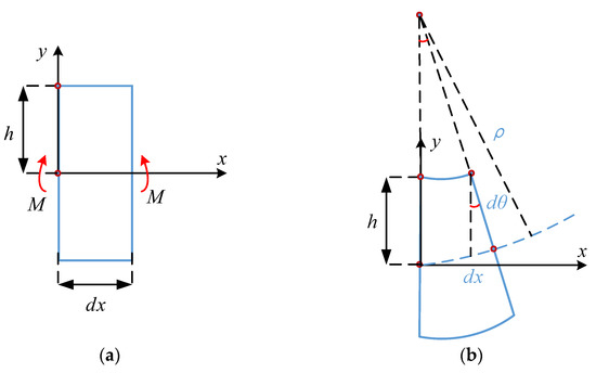
Figure 4.
Deformation of micro-segment beam: (a) micro-segment of a beam; and (b) deformation diagram.
The expression for the strain ε in the upper surface of the micro-segment is as follows:
From Equations (2) and (3):
From elastic beam theory, there is an expression [29]:
in Equations (4) and (5), ρ is the radius of curvature of the axis after bending; M is the bending moment and is a function of cross-section position x; and EI is the bending stiffness constant.
In this paper, the key problem is to improve the sensitivity of the fixed beam SAW yarn tension sensor. The sensitivity of the SAW yarn tension sensor reflects the change of sensor output frequency under unit tension [20]. According to the working principle of the SAW yarn tension sensor, the yarn tension causes elastic deformation of the piezoelectric substrate, which changes the center frequency of the SAW sensor; the expression is as follows [22]:
where f0 represents the output frequency of the SAW sensor (when the yarn tension, F = 0); k′ is the elastic stiffness constant of the piezoelectric substrate [22]; ε represents the strain of the piezoelectric substrate when the yarn tension F ≠ 0; and Δf is the corresponding frequency variation.
From Equation (6), under the action of tiny yarn tension, the strain, ε ≪ 1, which gives [16]:
As for the SAW yarn tension sensor, the position of the IDTs on the upper surface of the piezoelectric substrate directly affects the sensitivity of the sensor [16,22]. From Equation (6), it is obvious that the sensitivity of the SAW yarn tension sensor has a linear relationship with the strain of the piezoelectric substrate (IDTs placed part), under the same yarn tension.
Combining Equations (4), (5) and (7) yields:
As can be seen from Equation (8), the sensitivity of the SAW yarn tension sensor is linearly related to the absolute value of the bending moment of the beam (IDTs placed part), under the same yarn tension.
Therefore, this paper proposes a new type of SAW yarn tension sensor based on a simply supported beam structure that has a larger bending moment maximum compared with the fixed beam structure in [22] under the same yarn tension, and thus improves the sensitivity of the SAW yarn tension sensor. The comparative analysis of the bending moment distribution of these two types of beam structures, based on elastic beam theory, is shown in the next section.
3. Sensitivity Optimization Based on Elastic Beam Theory
The simply supported beam AB (a ≥ b) is shown in Figure 5a, and the solution process of its bending-moment equation is as follows:
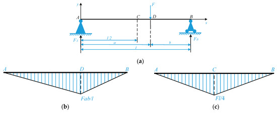
Figure 5.
Schematic diagram of simply supported beam and bending moment diagram: (a) the simply supported beam; (b) the bending moment diagram; and (c) the bending moment diagram (when F is loaded at the midpoint of the beam).
According to the static balance method, FA and FB are the binding forces of the beam at supports A and B, as follows:
Since there is a concentrated force, F at point D of the beam, it is necessary to divide it into part AD and part DB to establish the bending moment equation, respectively, i.e.:
where M1(x) and M2(x) represent the bending moment equations of part AD and part DB, respectively.
The bending moment diagram of the simply supported beam AB is shown in Figure 5b. According to Equation (10) or the bending moment diagram of a simply supported beam, it is obvious that the maximum, M1max, is as follows:
From Equation (11), when a = b = l/2, i.e., the concentrated load F acts on the midpoint of the beam, the bending moment of the simply supported beam AB reaches the maximum value, |MAB|max, as follows, and the maximum bending moment occurs at the midpoint of the beam; the bending moment diagram is shown in Figure 5c:
Therefore, for the simply supported beam SAW yarn tension sensor, the maximum sensitivity can be obtained when the IDTs are placed at the midpoint of the upper surface of the piezoelectric substrate and the yarn tension is loaded at the midpoint of the piezoelectric substrate.
As for the fixed beam SAW yarn tension sensor studied in [22], the concentrated load (yarn tension) is loaded at the midpoint of the piezoelectric substrate. For comparison, this paper only discusses the special case that the concentrated load, F acts on the midpoint of the fixed beam, as shown in Figure 6a.
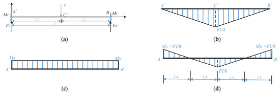
Figure 6.
Schematic diagram of fixed beam and bending moment diagrams: (a) the fixed beam; (b) the free bending moment diagram; (c) the fixed-end moment diagram; and (d) the resultant bending moment diagram.
In Figure 6a, MA′ and MB′ represent the fixed-end moments at the ends A′ and B′ of the fixed beam A′B′, respectively, and FA′ and FB′ are the binding forces of the beam at supports A′ and B′. From symmetry and the static balance method:
According to the elastic beam theory, the fixed beam A′B′ may be regarded as a simply supported beam carrying a concentrated load, F, at the midpoint of the beam and with the moments MA′ and MB′ applied at the supports A′ and B′. The bending moment diagrams corresponding to these two loading cases are shown in Figure 6b,c and are termed the free bending moment diagram and the fixed-end moment diagram [29], respectively.
According to the moment-area method [29], the area of the free bending moment diagram is numerically equal to the area of the fixed-end moment diagram. From Figure 6b,c:
which gives:
According to the superposition principle [29], the resultant bending moment diagram of the fixed beam A’B’ can be obtained, as shown in Figure 6d.
From the resultant bending moment diagram, it is obvious that there is a maximum bending moment, |MA’B’|max, of the fixed beam A’B’ at the midpoint of the beam, as follows:
Therefore, for the fixed beam SAW yarn tension sensor, in the case that the yarn tension is loaded at the midpoint of the piezoelectric substrate, the maximum sensitivity can be obtained when the IDTs are placed at the midpoint of the piezoelectric substrate.
The analysis results of the sensitivity optimization based on the elastic beam theory is shown in Figure 7. Figure 7a shows the structure diagram of the piezoelectric substrate of the simply supported beam SAW yarn tension sensor designed in this paper. The structure diagram of the piezoelectric substrate of the fixed beam SAW sensor, introduced in [22], is shown in Figure 7c. Moreover, Figure 7b shows the distribution diagram of the absolute value of the bending moments of the beams. As can be seen from Figure 7b, under the same yarn tension, the absolute value of the bending moment of the piezoelectric substrate (IDTs placed part) of the simply supported beam SAW yarn tension sensor studied in this paper is higher than that of the fixed beam sensor across the board, which means that the sensitivity of the simply supported beam SAW sensor will be significantly higher than that of the fixed beam sensor.
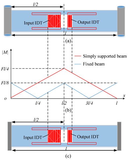
Figure 7.
The analysis results of sensitivity optimization based on the elastic beam theory: (a) structure diagram of the piezoelectric substrate of the simply supported beam SAW yarn tension sensor; (b) distribution diagram of the absolute value of bending moment; and (c) structure diagram of the piezoelectric substrate of the fixed beam SAW yarn tension sensor.
Through the above description, the sensitivity optimization method based on the elastic beam theory adopted in this paper can transform the sensitivity analysis of the sensor into the solution of the bending moment distribution of the beam structure, which is simple and efficient.
4. The Experimental Verification
4.1. Design of the Simply Supported Beam SAW Sensor
Figure 8 shows the model diagram of the simply supported beam SAW yarn tension sensor; it can be seen that the simply supported beam structure is composed of a fixed hinge support, a rolling support, and a piezoelectric substrate.
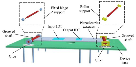
Figure 8.
Model diagram of simply supported beam SAW sensor.
For comparison purposes, the main design parameters of IDTs and piezoelectric substrate of the simply supported beam SAW sensor designed in this paper are the same as those of the fixed beam sensor. The IDTs with an unbalanced split electrode geometry were used in order to suppress the finger reflection effects, and the electrode-overlap envelope of the input IDT was weighted according to the Hamming function [22]. The main design parameters are shown in Table 1.

Table 1.
The main design parameters of the simply supported beam SAW sensor.
4.2. Experiment and Result Analysis
The picture of the simply supported beam SAW yarn tension sensor is shown in Figure 9. The frequency characteristics of the simply supported beam SAW sensor are shown in Figure 10. The center frequency of the SAW sensor at a temperature of 25 °C is about 59.797 MHz when the tension is equal to 0 N.
In this paper, the calibration experiment on the relationship between yarn tension F and the frequency variation Δf is performed. Figure 11 shows the measurement system of simply supported beam SAW yarn tension sensor. As can be seen from Figure 11, the yarn tension to be measured is loaded at the midpoint of the piezoelectric substrate by a rope sleeve and a guide pulley, and the output frequency of the sensor is detected by a network analyzer. In [22], the yarn tension is loaded on the piezoelectric substrate by a connecting rod. In this paper, the Aramid yarn with high modulus, stable size, and low shrinkage is used to replace the connecting rod, which reduces measurement errors and is more reliable.
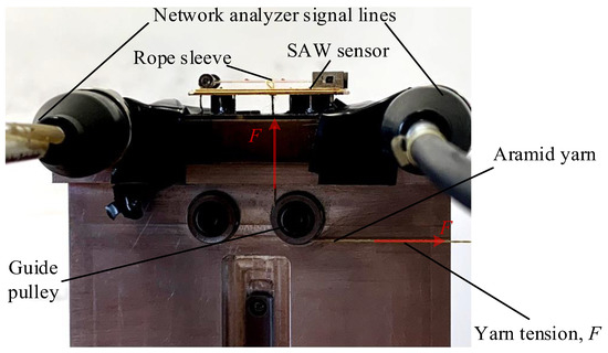
Figure 11.
The measurement system of simply supported beam SAW yarn tension sensor.

Figure 9.
The simply supported beam SAW yarn tension sensor.
Figure 9.
The simply supported beam SAW yarn tension sensor.


Figure 10.
Frequency characteristics of the simply supported beam SAW sensor (no force on the piezoelectric substrate, 25 °C).
Figure 10.
Frequency characteristics of the simply supported beam SAW sensor (no force on the piezoelectric substrate, 25 °C).

The yarn tension was tested in the range of 0–1 N at an ambient temperature of 25 °C. The experimental data of the calibration experiment are shown in Table 2. According to the least square fitting technique [30], the fitting linear equation between yarn tension F and the frequency variation Δf is as follows:
Table 2.
The data of the calibration experimental.
From Equation (17), the experimental result of the sensitivity of the simply supported beam SAW yarn tension sensor is 32.822 kHz/N, which is 2.5 times higher than that of the fixed beam sensor (in [22], the sensitivity of the fixed beam SAW yarn tension sensor is 12.996 kHz/N). According to the theoretical analysis result, the sensitivity of the simple supported beam SAW yarn tension sensor is theoretically twice that of the fixed beam sensor (i.e., the theoretical result of the sensitivity of the simple supported beam SAW yarn tension sensor is 25.992 kHz/N). The results are shown in Figure 12. Because of the optimization of the measurement system, the experimental result of the sensitivity of the simply supported beam SAW yarn tension sensor is better than the theoretical result.
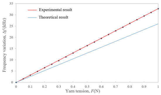
Figure 12.
Sensitivity analysis results of the simply supported beam SAW yarn tension sensor.
5. Conclusions
For the sensitivity enhancement of the fixed beam SAW yarn tension sensor, a new type of SAW yarn tension sensor based on simply supported beam is studied in this paper. The sensitivity analysis method based on elastic beam theory is proposed in this paper to illustrate the sensitivity difference between SAW yarn tension sensors with different structural forms, which is simple and efficient and can be used as an analysis tool for the sensitivity optimization of the SAW yarn tension sensors. According to the analysis results, the sensitivity of the SAW yarn tension sensor can be greatly improved by using a simply supported beam structure compared to the s fixed beam structure, without changing the size of the SAW sensor.
From the calibration experiment, it can be summarized that the sensitivity of simply supported beam SAW yarn tension sensor is 2.5 times higher than that of the fixed beam SAW yarn tension sensor. The research content of this paper illustrates the feasibility of the simply supported beam SAW yarn tension sensor in terms of sensitivity enhancement, which also contributes to the optimization and promotion of the SAW yarn tension sensor.
In practical applications, the stability of the simply supported beam SAW yarn tension sensor relies heavily on a rational structural design (the implementation of the fixed hinge support and the rolling support) and a sophisticated manufacturing process. In addition, the application to some textile machinery with limited space requires more efforts in the further integration and miniaturization of the sensor.
Author Contributions
Conceptualization, Y.D.; methodology, Y.D. and L.G.; software, Y.D.; validation, W.L.; formal analysis, Y.D. and L.G.; investigation, L.G.; resources, L.G. and W.L.; data curation, Y.D.; writing—original draft preparation, Y.D.; writing—review and editing, W.L.; visualization, Y.D. and L.G.; supervision, W.L.; project administration, W.L. All authors have read and agreed to the published version of the manuscript.
Funding
This research was supported by the National Natural Science Foundation of China for Youth (61907023), the National Natural Science Foundation of China (61274078), the applied basic research project of “The Textile Light” (J201608), and the Fundamental Research Funds for the Central Universities and Graduate Student Innovation Fund of Donghua University (CUSF-DH-D-2020082).
Institutional Review Board Statement
Not applicable.
Informed Consent Statement
Not applicable.
Data Availability Statement
The data reported in this manuscript is accessible based on reasonable requests to the corresponding author.
Conflicts of Interest
The authors declare no conflict of interest.
References
- Zhang, D.; Ma, Q.; Tan, Y.; Liao, H.; Lu, C.; Tang, F.; Liu, X.; Fu, Y.; Wang, X.; Gan, X. Non-contact detection of polyester filament yarn tension in the spinning process by the laser Doppler vibrometer method. Text. Res. J. 2022, 92, 919–928. [Google Scholar] [CrossRef]
- Ali, M.; Ahmed, R.; Amer, M. Yarn tension control technique for improving polyester soft winding process. Sci. Rep-UK. 2021, 11, 1060. [Google Scholar] [CrossRef] [PubMed]
- Nilsson, E.; Lund, A.; Jonasson, C.; Johansson, C.; Hagström, B. Poling and characterization of piezoelectric polymer fibers for use in textile sensors. Sens. Actuators A. Phys. 2013, 201, 477–486. [Google Scholar] [CrossRef]
- Chen, X.L.; Mei, S.Q.; Chen, X.B. Non-Contact Measurement of Yarn Tension in Spinning Process. Appl. Mech. Mater. 2014, 722, 367–372. [Google Scholar] [CrossRef]
- Liu, S.B.; Lu, W.K. Manufacturing error correction model of the wavelet transform processor using surface acoustic wave devices. IEICE Electron Expr. 2017, 14, 1–6. [Google Scholar] [CrossRef][Green Version]
- Lu, W.K.; Gao, L.L.; Liu, Q.H. Electrode-width-weighted wavelet transform processor using SAW devices. Microelectron Int. 2017, 34, 75–83. [Google Scholar] [CrossRef]
- Liu, S.B.; Lu, W.K.; Zhu, C.C. Research on two-port network of wavelet transform processor using surface acoustic wavelet devices and its application. Ultrasonics 2017, 81, 81–85. [Google Scholar] [CrossRef]
- Jiang, H.; Lu, W.K.; Zhang, G.A. Study of low insertion loss and miniaturization wavelet transform and inverse transform processor using SAW devices. Ultrasonics 2013, 53, 992–997. [Google Scholar] [CrossRef]
- Lu, W.K.; Gao, L.L.; Zhang, J.D. A novel electrode-area-weighted method of implementing wavelet transform processor with surface acoustic wave device. Int. J. Circ. Theor. Appl. 2016, 44, 2134–2146. [Google Scholar] [CrossRef]
- Lu, W.K.; Zhu, C.C.; Liu, Q.H.; Zhang, J.D. Implementing wavelet inverse-transform processor with surface acoustic wave device. Ultrasonics 2013, 53, 447–454. [Google Scholar] [CrossRef]
- Nilsson, E.; Lund, A.; Jonasson, C.; Johansson, C.; Hagström, B. Colloidal quantum dot-based surface acoustic wave sensors for NO2-sensing behavior. Sensor Actuat. B-Chem. 2019, 287, 241–249. [Google Scholar] [CrossRef]
- Rana, L.; Gupta, R.; Tomar, M.; Gupta, V. Highly sensitive Love wave acoustic biosensor for uric acid. Sensor Actuat. B-Chem. 2018, 261, 169–177. [Google Scholar] [CrossRef]
- Xu, Z.; Yuan, Y.J. Implementation of guiding layers of surface acoustic wave devices: A review. Biosens. Bioelectron. 2018, 99, 500–512. [Google Scholar] [CrossRef]
- Liu, S.B.; Xue, P.; Lu, J.Y.; Lu, W.K. Fitting analysis and research of measured data of SAW yarn tension sensor based on PSO–SVR model. Ultrasonics 2021, 116, 106511. [Google Scholar] [CrossRef]
- Lei, B.; Lu, W.; Zhu, C.; Liu, Q.; Zhang, H. Optimization of Sensitivity Induced by Substrate Strain Rate for Surface Acoustic Wave Yarn Tension Sensor. IEEE Sens. J. 2015, 15, 4769–4776. [Google Scholar] [CrossRef]
- Lei, B.B.; Lu, W.K.; Mian, Z.B.; Bao, W.X. Effect of IDT position par-ameters on SAW yarn tension sensor sensitivity. Meas. Control. 2020, 53, 2055–2062. [Google Scholar] [CrossRef]
- Lu, X.Z.; Lu, W.K.; Zhu, C.C. Compensated SAW Yarn Tension Sensor. IEEE Trans. Instrum. Meas. 2014, 63, 3162–3168. [Google Scholar] [CrossRef]
- Lu, W.; Lu, X.; Zhu, C.; Liu, Q.; Zhang, H. Solving three key problems of the SAW yarn tension sensor. IEEE Trans. Electron. Devices 2012, 59, 2853–2855. [Google Scholar] [CrossRef]
- Lu, W.K.; Feng, Y.; Zhu, C.C.; Zhen, J.L. Temperature compensation of the SAW yarn tension sensor. Ultrasonics 2017, 76, 87–91. [Google Scholar] [CrossRef]
- Ding, Y.; Lu, W.K.; Zhang, Y.H. Study on the Practical Application of Surface Acoustic Wave Yarn Tension Sensor. IEEE Trans. Ind. Electron. 2022, 69, 13781–13790. [Google Scholar] [CrossRef]
- Lei, B.B.; Lu, W.K.; Zhu, C.C.; Liu, Q.H.; Zhang, H.X. A novel optimal sensitivity design scheme for yarn tension sensor using surface acoustic wave device. Ultrasonics 2014, 54, 1649–1655. [Google Scholar] [CrossRef] [PubMed]
- Feng, Y.; Lu, Z.X.; Lu, W.K. Study of the Doubly Clamped Beam Yarn Tension Sensor Based on the Surface Acoustic Wave. IEEE Trans. Ind. Electron. 2019, 66, 3256–3264. [Google Scholar] [CrossRef]
- Logan, D.L. A First Course in the Finite Element Method, 4th ed.; Cengage Learning: Stamford, CT, USA, 2007; pp. 748–754. [Google Scholar]
- Štalmach, O.; Sapietová, A.; Dekýš, V.; Šulka, P.; Gajdoš, L. Conversion of data from the laser scanner to the Ansys Workbench. MATEC Web Conf. 2019, 254, 02003. [Google Scholar] [CrossRef]
- Cai, Y.; Zhang, K.; Ye, Z.; Liu, C.; Lu, K.; Wang, L. Influence of Temperature on the Natural Vibration Characteristics of Simply Supported Reinforced Conc-rete Beam. Sensors 2021, 21, 4242. [Google Scholar] [CrossRef]
- Gautam, B.G.; Xiang, Y.; Liao, X.; Qiu, Z.; Guo, S. Experi-mental Investigation of a Slip in High-Performance Steel-Concrete Small Box Girder with Different Combinations of Group Studs. Materials 2019, 12, 2781. [Google Scholar] [CrossRef] [PubMed]
- Xu, H.; Ren, W.X.; Wang, Z.C. Deflection Estimation of Bending Beam Structures Using Fiber Bragg Grating Strain Sensors. Adv. Struct. Eng. 2015, 18, 395–403. [Google Scholar] [CrossRef]
- Trahair, N.S. Inelastic lateral buckling of steel cantilevers. Eng. Struct. 2020, 208, 109918. [Google Scholar] [CrossRef]
- Megson, T.H.G. Structural and Stress Analysis, 4th ed.; Butterworth-Heinemann Elsevier Ltd: Oxford, UK, 2019; pp. 337–388. [Google Scholar]
- Kurt, O.; Arslan, O. A general accuracy measure for quality of elliptic sections fitting. Measurement 2019, 145, 640–647. [Google Scholar] [CrossRef]


Publisher’s Note: MDPI stays neutral with regard to jurisdictional claims in published maps and institutional affiliations. |
© 2022 by the authors. Licensee MDPI, Basel, Switzerland. This article is an open access article distributed under the terms and conditions of the Creative Commons Attribution (CC BY) license (https://creativecommons.org/licenses/by/4.0/).