Article

Silicon Self-Switching Diode (SSD) as a Full-Wave Bridge Rectifier in 5G Networks Frequencies

by
Tan Yi Liang
1,
Nor Farhani Zakaria
1,2,*,
Shahrir Rizal Kasjoo
1,2,
Safizan Shaari
1,2,
Muammar Mohamad Isa
1,
Mohd Khairuddin Md Arshad
1 and
Arun Kumar Singh
3
1
Faculty of Electronic Engineering Technology, Universiti Malaysia Perlis (UniMAP), Arau 02600, Perlis, Malaysia
2
Advanced Communication Engineering, Centre of Excellence (ACE), Universiti Malaysia Perlis (UniMAP), Kangar 01000, Perlis, Malaysia
3
Department of Electronics and Communication Engineering, Punjab Engineering College (Deemed to Be University), Sector-12, Chandigarh 160012, India
*
Author to whom correspondence should be addressed.
Sensors 2022, 22(24), 9712; https://doi.org/10.3390/s22249712
Submission received: 9 November 2022 / Revised: 27 November 2022 / Accepted: 9 December 2022 / Published: 11 December 2022

Abstract

:
The rapid growth of wireless technology has improved the network’s technology from 4G to 5G, with sub-6 GHz being the centre of attention as the primary communication spectrum band. To effectively benefit this exclusive network, the improvement in the mm-wave detection of this range is crucial. In this work, a silicon self-switching device (SSD) based full-wave bridge rectifier was proposed as a candidate for a usable RF-DC converter in this frequency range. SSD has a similar operation to a conventional pn junction diode, but with advantages in fabrication simplicity where it does not require doping and junctions. The optimized structure of the SSD was cascaded and arranged to create a functional full-wave bridge rectifier with a quadratic relationship between the input voltage and outputs current. AC transient analysis and theoretical calculation performed on the full-wave rectifier shows an estimated cut-off frequency at ~12 GHz, with calculated responsivity and noise equivalent power of 1956.72 V/W and 2.3753 pW/Hz1/2, respectively. These results show the capability of silicon SSD to function as a full-wave bridge rectifier and is a potential candidate for RF-DC conversion in the targeted 5G frequency band and can be exploited for future energy harvesting application.

1. Introduction

In recent years, the 5th generation (5G) technology has attracted the interest of researchers as 4G has matured, therefore only little improvement and several fresh carrier proficiencies can be expected [1,2]. This 5G technology has contributed to the rapid spread of the Internet of Things (IoT), where it wirelessly connects a huge number of physical items such as wearable devices [3], smart home sensors [4], industrial sensors, and agricultural sensors to deliver services such as healthcare, smart industry, and smart agriculture [5]. In the construction of the IoT environment, energy limitation was revealed as one of the huge challenges faced by the IoT application, where most of the IoT application, especially in portable and wearable devices, require long last battery and energy [6].
The application of green energy technologies for energy harvesting (EH) are important tools in prolonging the lifetime of the IoT, extending the lifetime of wireless energy-constrained networks by avoiding the need for hard-wiring or replacing mobile batteries [7,8]. Conventional energy harvesting systems extract energy from the environment via the sun [9], wind, vibration, thermoelectric effects [10], or other physical phenomena, which are less applicable in the scenario where access to external energy sources are limited [11,12]. With the vast availability of radio frequency (RF) transmitters (mobile base stations, TV and radio stations, Wi-Fi routers, etc.), ambient RF transmissions were a promising approach with the advantage of transporting energy and information [13].
Figure 1 shows the illustration of an RF energy harvesting system, which consists of a transmission antenna, receiving antenna, impedance matching network (IMN), rectifier circuit, and load [14]. The RF signals are first transmitted by the transmission antenna and then received by the receiving antenna. The IMN adjusts the impedance between the receiving antenna and the rectifier circuit. In the absence of IMN, all the energy received by the system will be reflected, causing a decreased amount of rectified output current obtained by the load [15]. The RF signals are then transferred from the IMN to the rectifier circuit for radio frequency waves to direct current (RF-DC) conversion, before being supplied to the load. In 5G networks, the RF range is in the millimeter wave (mm-wave) band, which includes frequencies ranging from 3 GHz to 300 GHz [16]. These mm-wave band operation frequencies as presented by the 3rd Generation Partnership Project (3GPP) consists of frequency range 1 (FR1) and frequency range 2 (FR2), operating at a frequency range of 450 MHz to 6 GHz and 24.25 GHz to 52.6 GHz, respectively [17].
The motivation of this research is to accommodate the RF-DC energy harvesting system in the 5G networks frequencies by providing an alternative device for an efficient RF-DC conversion. Most widely used and marketed rectifiers in the microwave region is the Schottky diode, where it brings an advantage of a higher turn-on voltage compared to a conventional pn junction diode. Other silicon-based bridge rectifiers focusing on 5G networks frequencies are also shown in Table 1, and most are seen focusing on the lower FR1 of the 5G spectrums. The fabrication process steps in all existing silicon-based rectifiers consists of complex fabrication steps, with the involvement of multiple doping layers, and multiple steps of lithography process for device patterning.
In this work, a full-wave bridge rectifier for sustainable 5G network application is proposed by using a silicon-based self-switching device (SSD) [15]. SSDs have received attention from researchers worldwide as they have been reported to effectively function as zero-bias RF detectors [8,18]. The rectification property of the SSD is similar to a pn junction diode, with simplicity in fabrication process where it can be simply realized by one-step lithography process and chemical etching, and does not involve junctions, doping, or third gate terminal [19]. In SSD, a pair of L-shaped trench are etched between two electrodes, resulting in depletion region in between the etched region (air) and silicon [20]. Depending on the bias given, the thickness of this depletion region can be controlled to open and close the channel, which created a non-linear response of the IV characteristic, similar to a conventional diode. In addition, the planar configuration of the SSD where all the electrical contacts are in the same plane will result in a smaller parasitic capacitance compared to other diodes [21,22].
Table 1. The results reported from previous works on bridge rectifier.
RectifierFrequencyFabrication Process StepsSimulation/
Fabrication
References
Schottky barrier diode
Bridge rectifier
2.45 GHz-Simulation[23]
Schottky barrier diode bridge rectifier100 MHz
2.45 GHz
-Simulation[24]
NMOS bridge rectifier13.56 MHz-Simulation[25]
SOI CMOS bridge rectifier2.45 GHz-Simulation[26]
Integrated 4H-Silicon Carbide diode bridge rectifier-etching, annealing, patterning and metal depositionFabrication[27]
GaAs Schottky diodes bridge rectifier-heavily doping, lightly doping, etching and metal depositionFabrication[28]
Oxide TFT Rectifiers-multi dry etching, multi depositionFabrication[29]
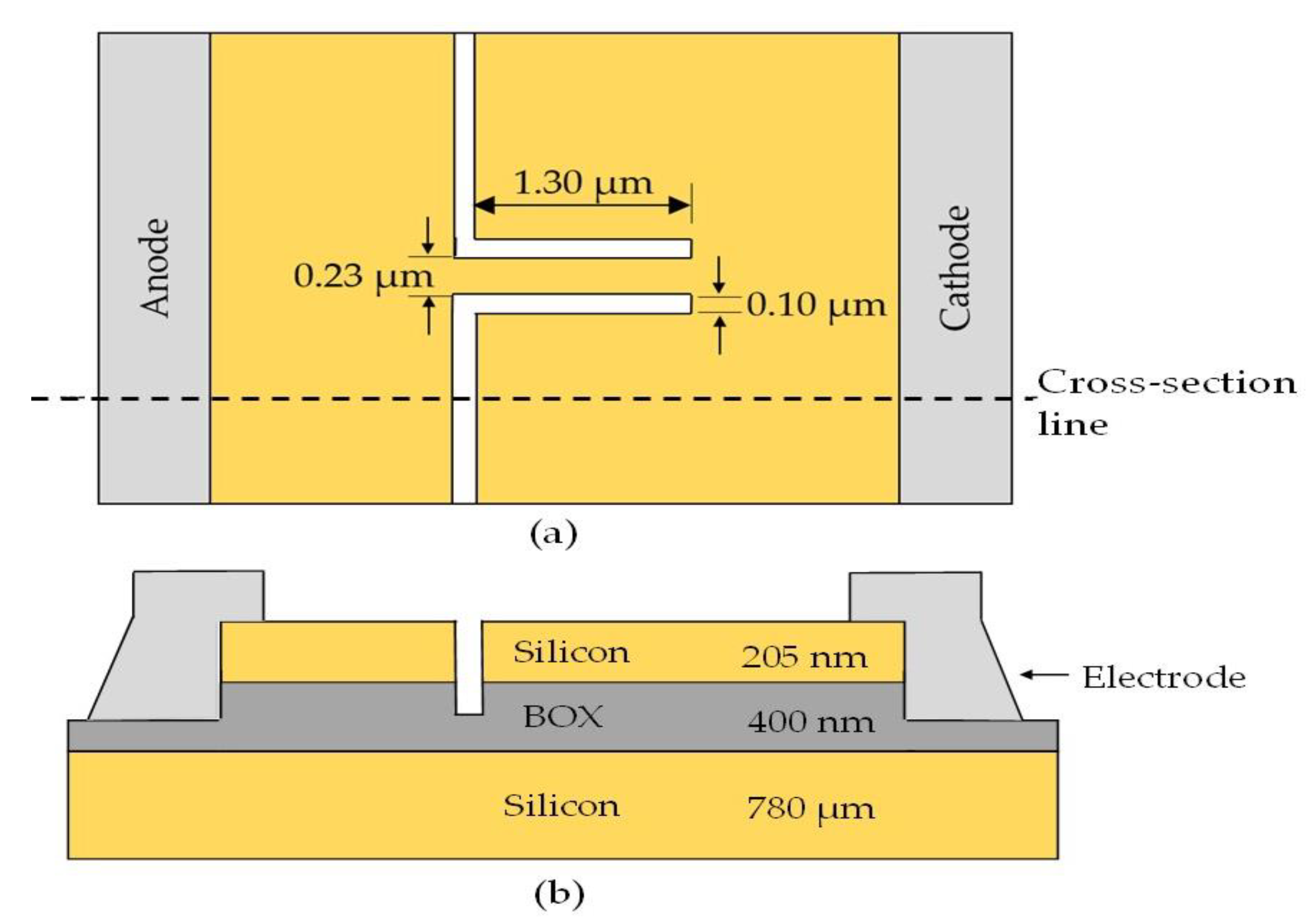
SSD as a full wave bridge rectifier has only been evaluated on graphene-based SSD targeting a higher Terahertz frequency region. However, the feasibility issues and usefulness of a graphene based rectenna in ambient RF harvesting is minimal [30] and patterning issues of graphene for integration with electronic devices in the realization of monolithic-integration microwave integrated circuits (MMIC) is a big hurdle to overcome [31]. Therefore, in this paper, the capability of a silicon-based SSD to function as a full-wave bridge rectifier to convert RF to DC is examined and concluded for better integration with current CMOS technology, and for future implementation in a RF-DC energy harvesting system. Furthermore, an optimized structure of a silicon based SSD is shown in Figure 2, which has been reported in [32] and shows a cut-off frequency at around 6.50 GHz, where it shows a promising capability to operate in the FR1 of the 5G spectrums [32], which carried most of the traditional cellular mobile communications traffic [33,34]. In addition, experimental research on silicon-based SSD shows no leakage and breakdown voltage from 0 to −5 V bias which is an advantage to a rectifier device [35].

2. Materials and Methods

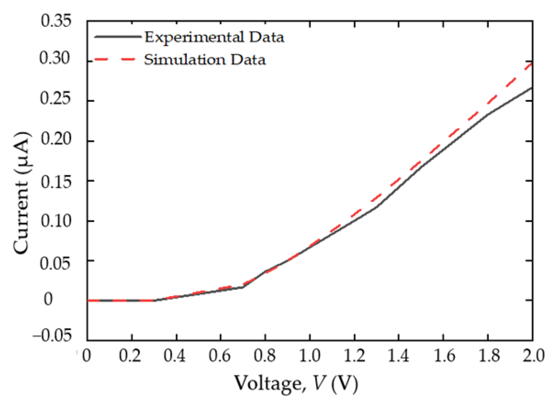
Prior to the design of the full-wave bridge rectifier, a validation process on the physical models and material parameters of the SSD defined in the device simulator (ATLAS Silvaco) were performed by comparing the electrical characteristics to the experimental results of a silicon SSD structure from [35]. A p-type silicon substrate SSD with doping concentration of 2.45 × 1016 cm−3 were defined with interface charge density of 3.16 × 1011 cm−2 along the channel [35,36]. In addition, physical models such as Klaassen’s unified low-field mobility model, the Watt model, Auger recombination, and the energy balance transport were implemented in the simulation to imitate the electron transport mechanism of the real device [32]. As shown in Figure 3, the I-V characteristics of the simulated and experimental data [35] were in good agreement, which validated the models and parameters used in the simulation.
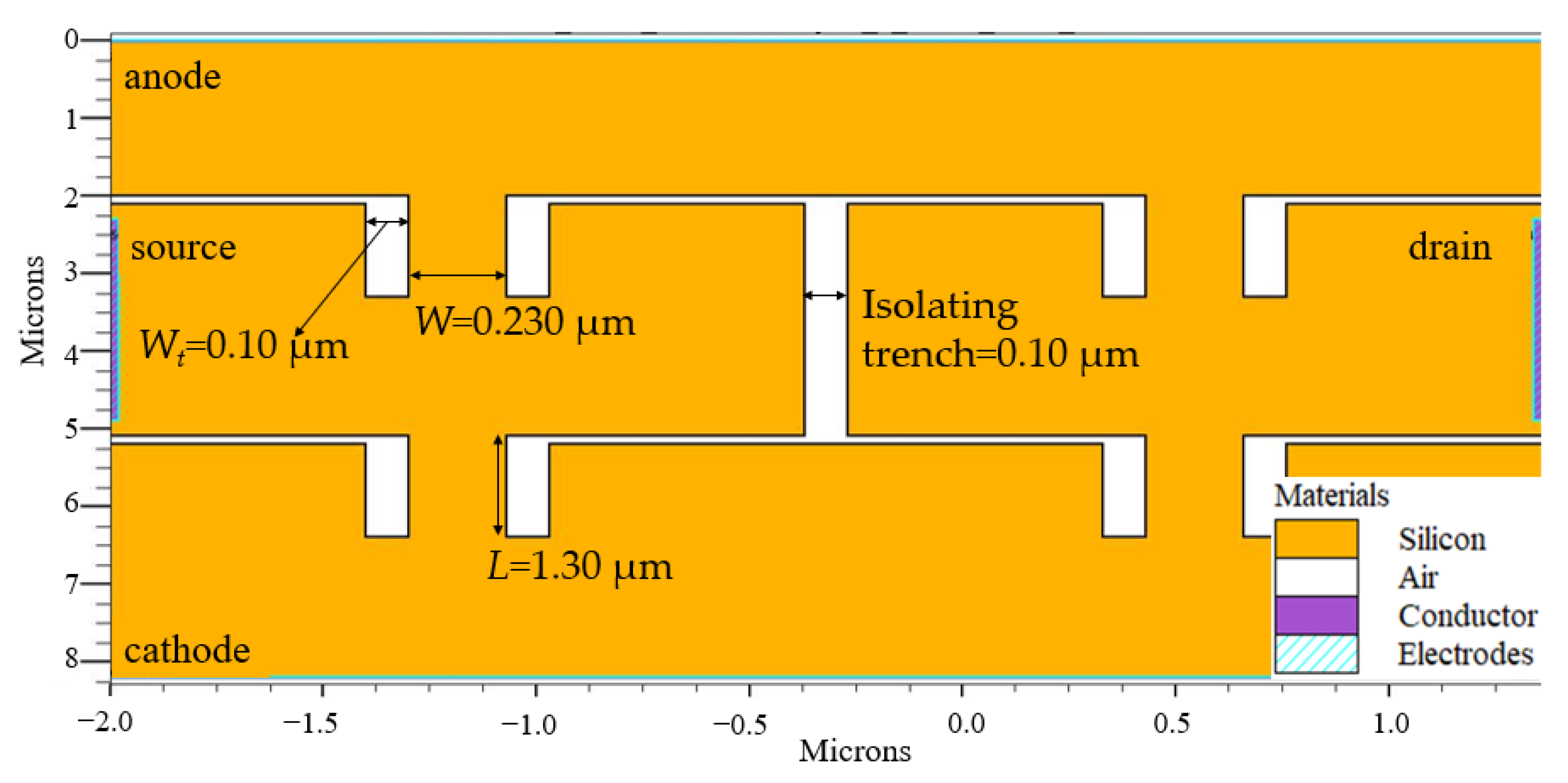
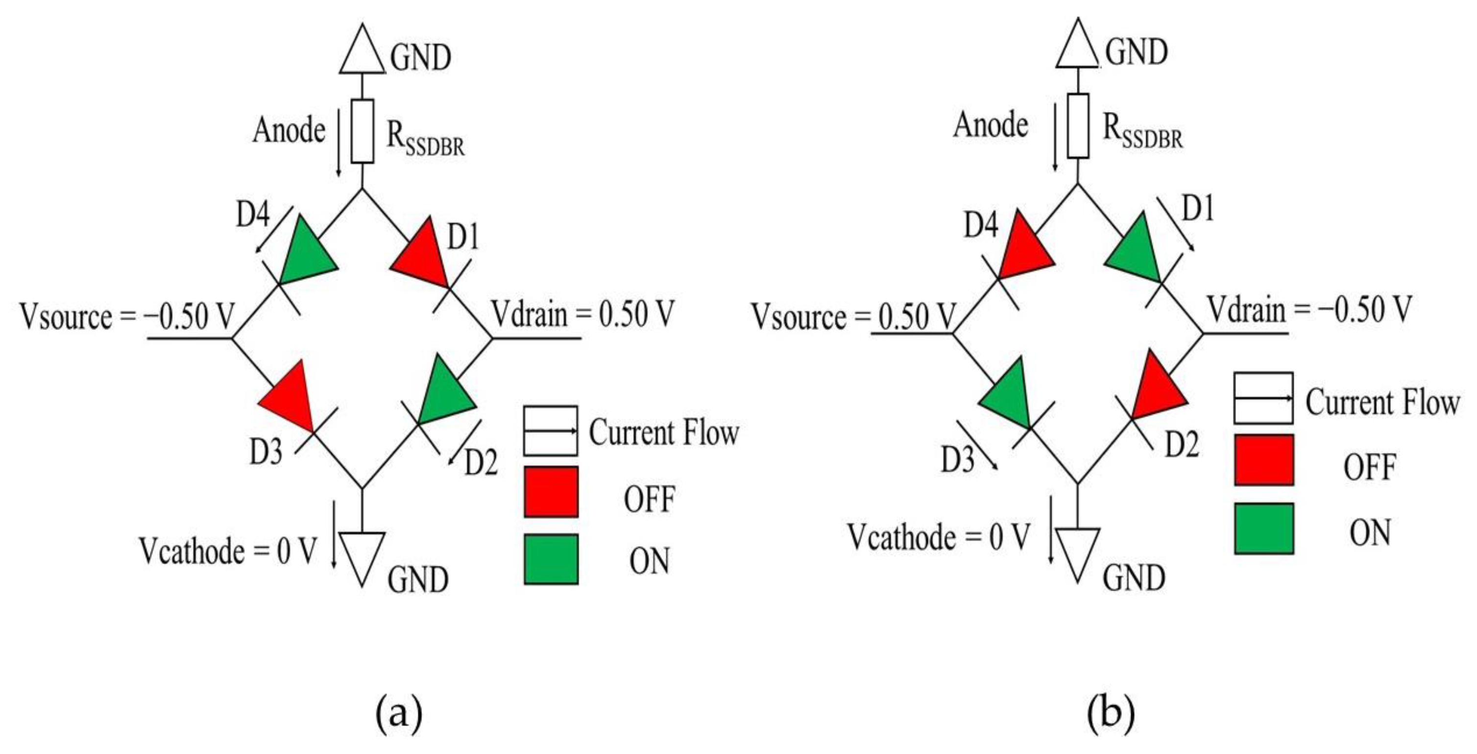
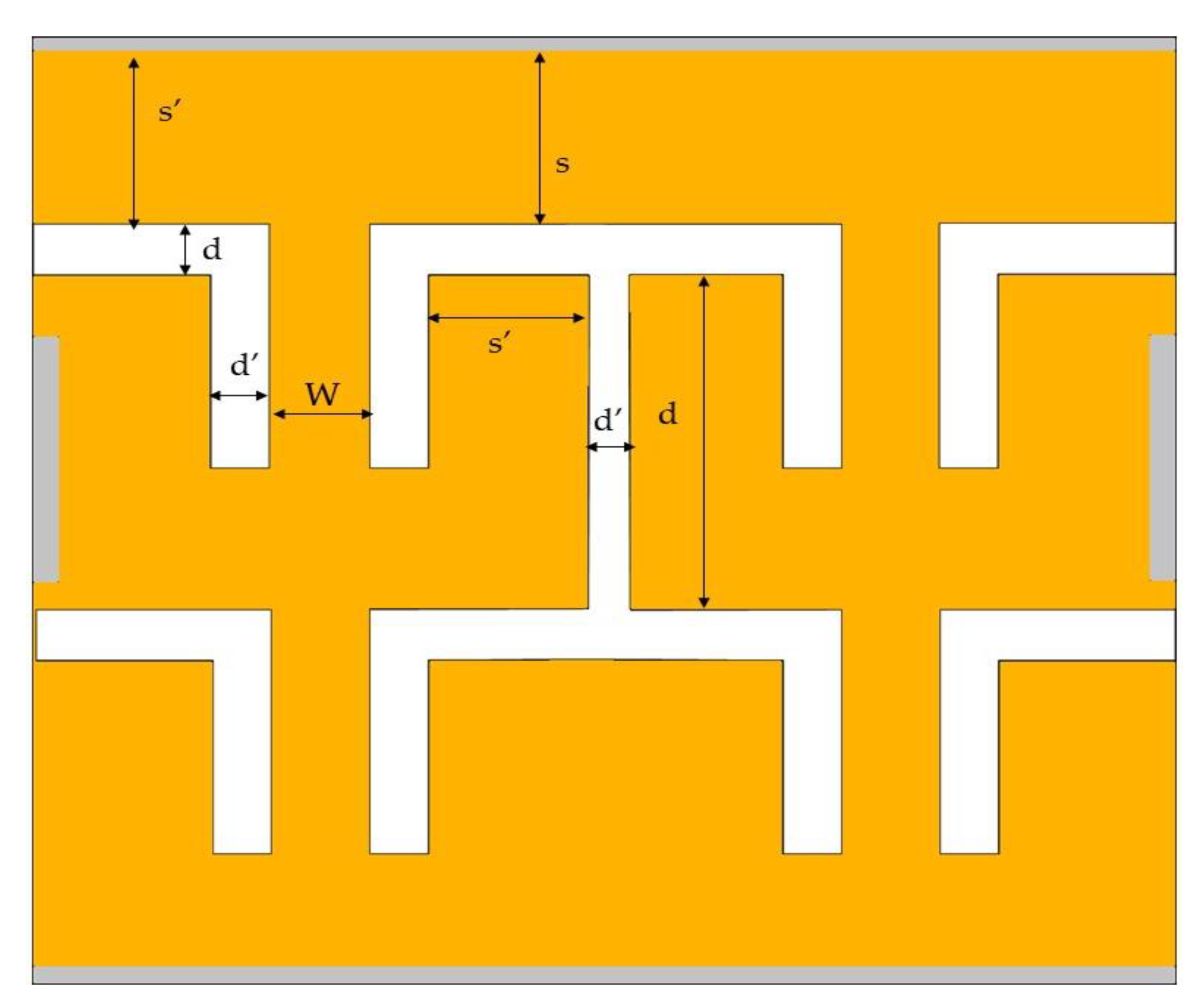
A full-wave bridge rectifier was then designed using the optimized structure of silicon-based SSD as shown in Figure 2. The full-wave bridge rectifier, as shown in Figure 4, consists of four electrodes; drain, source, anode, and cathode at the right, left, top, and bottom of the device, respectively. An isolating trench with a width of 0.10 µm was also etched between the SSD’s two series connection. This trench separates the SSDs in the series network. For ease of understanding, the mechanism of this full-wave bridge rectifier is explained as the equivalent diode-based circuit diagram (representing the SSD) in Figure 5.
Two different current flows occurred when different polarities of the AC input signals are applied to the source and drain. When the source and drain are applied −0.50 V and 0.50 V, respectively, the D2 and D4 are in forward bias and D1 and D3 are in reverse bias, as shown in the circuit diagram of Figure 5a. The cathode is applied 0 V bias to act as a ground. Figure 5b is the diagonal opposite operation of Figure 5a when the polarities of the drain and source are changed to −0.50 V and 0.50 V, respectively, while keeping the cathode at 0 V. A series resistance, RSSDBR of 615 kΩ were also defined in the simulation to imitate real SSD resistance [35].
To examine the current output response of the device, DC and AC transient analyses were conducted on the device using ATLAS Silvaco device simulator. Based on the I-V characteristic obtained from the DC analysis, the noise equivalent power (NEP) and responsivity were calculated, which indicates the minimal detectable power per square root bandwidth and the rectification performance of the full-wave bridge rectifier, respectively. Furthermore, to imitate the RF sinusoidal waves input in different frequencies, an AC input signal were given at the source and drain from 1 to 12 GHz frequency and the DC output current responses were recorded. The cut-off frequency was then evaluated by analyzing the DC output current response to observe the maximum frequency that the full-wave bridge rectifier can rectify.

3. Results and Discussion

3.1. The Mechanism of the SSD Full-Wave Bridge Rectifier

Figure 6 shows the hole current density that flowed across the SSD, representing the biasing condition of the conventional full-wave bridge rectifier obtained from the Silvaco TonyPlot 2D software version 5.0.22.R by Silvaco company from Santa Clara, California. The biasing conditions and current flows were similar to the mechanism explained in diode-based circuit diagram of Figure 5a,b, where in the positive cycle of Figure 6a, the SSDs representing D1 and D2 are in forward bias, while no current flow in D3 and D4, which indicates reverse bias. In negative cycle of Figure 6b, the SSDs representing D3 and D4 are in forward bias, while D1 and D2 are in reverse bias.

3.2. I-V Characteristics of the SSD Full-Wave Bridge Rectifier

Figure 7 shows the I-V characteristic of the SSD with varied DC bias voltages from −0.5 V to 0.5 V. From the graph, it can be observed that the output currents of the full-wave bridge rectifier are always positive regardless of the polarity of the voltage applied in the source and drain. The highest output current achieved from both positive and negative cycle was 0.05361 µA at V = 0.5 V and V = −0.5 V, respectively, which is higher than the reported output current value of 0.04274 µA at V = 0.5 V in single optimized SSD structure [32]. When source and drain were applied with voltage, some of the holes and electrons diffused through the isolating trench causing the concentration of holes and electrons to increase. This could cause threshold voltage drop in the device with increased forward current behavior. This brings an advantage of a faster turn-on transition in between both negative and positive polarities of the sinusoidal RF waveform in full wave rectifier configuration.
Moreover, the noise equivalent power (NEP) and responsivity was calculated from the I-V characteristics to determine the rectification performance of the full-wave bridge rectifier using the equation of:
β = 2 R s γ
where β is the responsivity, Rs is the source impedance and γ is the curvature coefficient [28]. The β value obtained was 1956.72 V/W with Rs = 50 Ω and γ = 19.5672 V−1. This responsivity value is better than the holes of SSD full-wave bridge rectifier reported in graphene which was reported at 1571 V/W [37].
The NEP of the device was also calculated to determine the minimal detectable power per square root bandwidth by using the equation of:
N E P = 4 k T R β
where k is the Boltzmann constant, R is the zero-bias resistance and T is the temperature [38,39]. This parameter may show the measure of the sensitivity in a detector system in a device level. The NEP obtained was 2.3753 pW/Hz1/2 with R = 1.3036 kΩ and T = 300 K, which also shows better performance compared to SSD full-wave bridge rectifier’s NEP in graphene, which is 18.2 pW/Hz1/2 [37].

3.3. Rectification of the SSD Full-Wave Bridge Rectifier

Figure 8a–d shows simulated AC input signals with an amplitude of 0.5 V were inserted between drain and source to imitate the RF wave into the devices, at frequency of 1, 5, 10, and 12 GHz, respectively. The respective current output response of the rectifier were observed at the anode, and are shown in Figure 8e,h. As can be observed, at 1 GHz, the output responded well to the input signal with high current output values both in positive and negative polarity of the drain voltage. Additionally, in higher frequency, the amplitude of the DC outputs was observed lower with reduced peak in opposite polarity at second peak. Since energy of radiation is inversely proportional to its wavelength, it can be observed that the amplitude of the output current decreased in lower wavelength (higher frequencies). The ripple is however reduced at higher input switching frequency because of the faster transition between the positive and negative input cycles.

3.4. Cut-Off Frequency of the SSD Full-Wave Bridge Rectifier

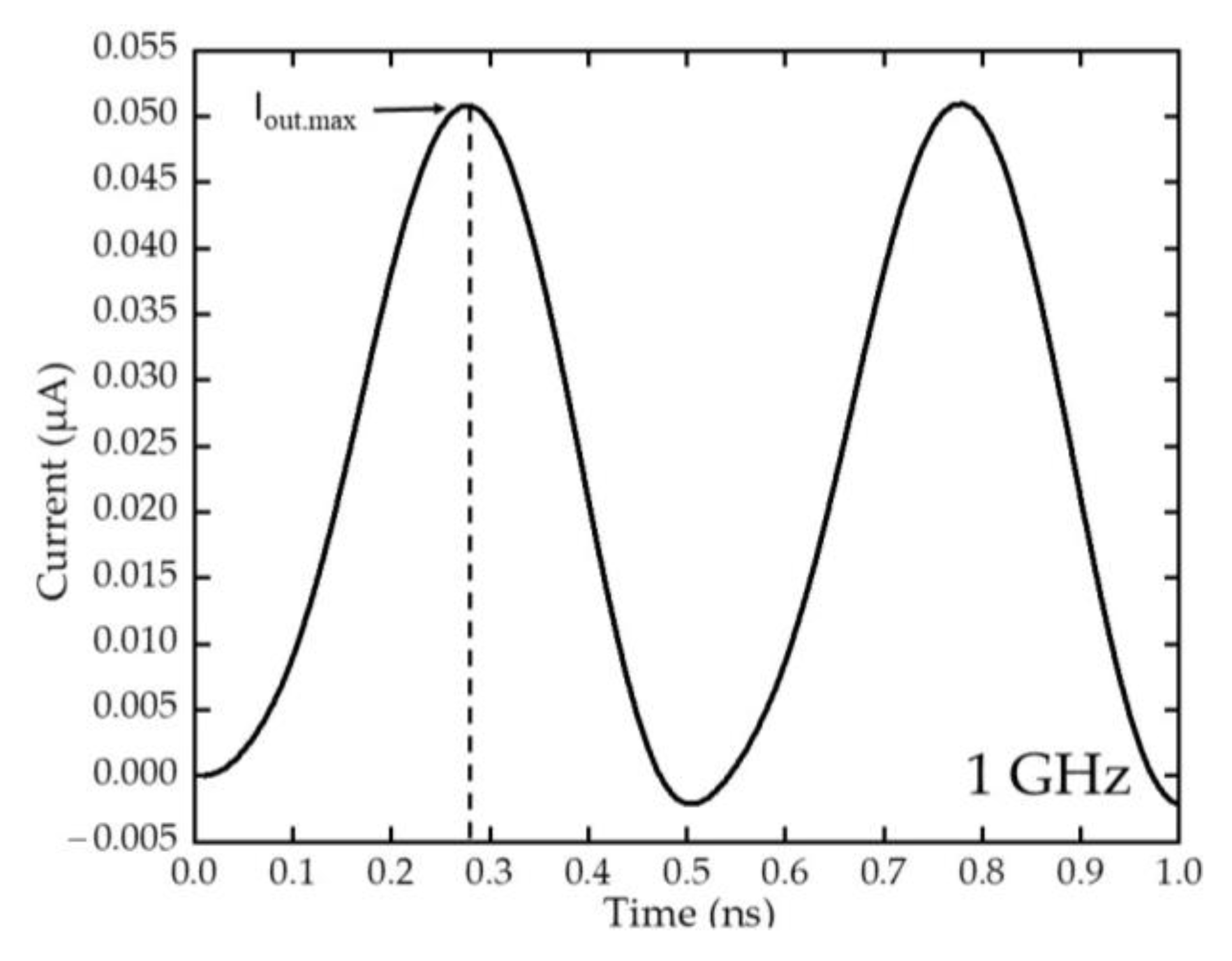
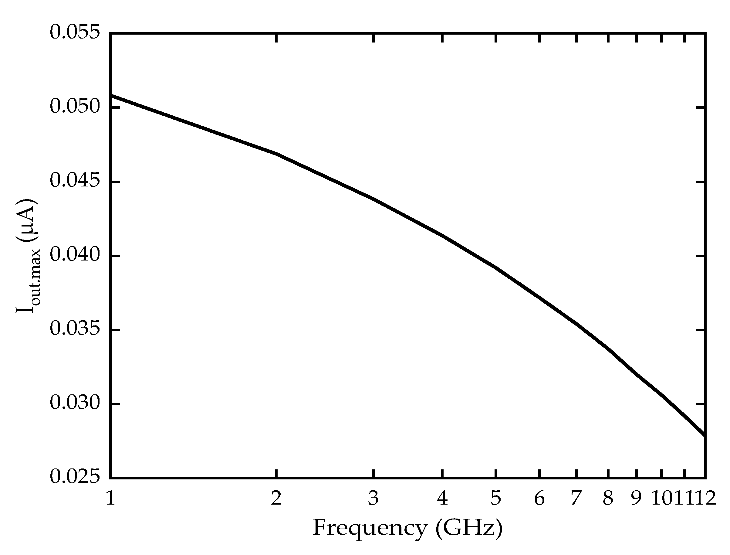
The maximum rectified output current, Iout.max from the AC signal analysis were obtained, as shown in Figure 9, and the Iout.max from 1GHz to 12 GHz were plotted in Figure 10. As can be observed, the Iout.max can be seen decreased when the frequency increased, with the highest Iout.max value observed at 50.82 nA with 1 GHz frequency input. The value continues to decrease to around 30.60 nA at 10 GHz, because of the reduced energy in higher frequency as explained in Section 3.3 [40]. This current output value at 10 GHz is comparable to previous energy harvesting research by using piezo-triboelectric hybrid nanogenerator which has obtained a 30 nA output as an operable current output [41]. Additionally, since the device is targeting the FR1 frequencies at sub-6 GHz frequency, the current output at 6 GHz is being focused which shows 37 nA of usable current output.
To verify the cut-off frequency of the bridge rectifier obtained from the device simulator, a theoretical calculation of the cut-off frequency was conducted using Equation (3) [42,43,44]:
f c = 1 2 π R S S D B R C S S D B R
where RSSDBR is the resistance of the SSD full-wave bridge rectifier and CSSDBR is the calculated capacitance of the full-wave bridge which is the combination of two SSDs channel capacitances, CSSD and trench capacitance, Ctrench, as illustrated in Figure 11. In one complete cycle, the currents will be passing through two diagonally connected SSDs. Additionally, at high frequencies, holes are diffused through the trench causes induced extrinsic capacitance, which also decreases the overall output current as observed in Figure 8a–g.
The capacitances were calculated by using conformal mapping techniques [45,46] which involves the equations shown in Equations (4)–(6) below:
C v ε r ε o = 1 π ( 8 s d ) , s d
C v ε r ε o = π l n [ 4 ( d / s ) ]
C H = 4 π ε r ε o ( π ln ( 4 k 1 ) ) , k 1 = a b c 2 b 2 c 2 a 2 , a = W 2 , b = ( W 2 + d ) , c = ( W 2 + d + s )
where the relative permittivity, εr = 6.34 with conformal mapping parameters as shown in Figure 12 and Table 2. This εr value is the average value of dielectric constant of silicon (εr = 11.68) and air (εr = 1).
The calculated CSSD was 1.785 × 10⁻¹⁶ F using Equations (4) and (6), while Ctrench = 3.6701 × 10⁻¹⁷ F using Equations (4) and (5). The total CSSDBR obtained from the addition of CSSD and Ctrench is CSSDBR = 2.1838 × 10⁻¹⁷ F with 0.205 µm thickness active device layer. The cut-off frequency calculated using Equation (3) shows cut-off value at 12 GHz which is well in accordance with the simulated results showed in Figure 10.

4. Conclusions

A full-wave bridge rectifier based on silicon self-switching device (SSD) were proposed in this work. The simulation result and analyses show a usable output current value around 30.60 nA at 10 GHz frequency, with cut-off at around 12 GHz. The results obtained in this research proves the capability of the silicon-based SSD full-wave bridge rectifier to function as the RF-DC converter in the FR1 spectrum of the 5G networks. Furthermore, the calculated responsivity and noise equivalent power (NEP) obtained in this work were 1956.72 V/W and 2.3753 pW/Hz1/2, respectively, which shows better performance than previously reported graphene-based SSD full-wave bridge rectifier and makes it a good candidate as a full-wave bridge rectifier.

Author Contributions

Conceptualisation, N.F.Z. and S.R.K.; methodology, T.Y.L., N.F.Z. and M.M.I.; software, A.K.S.; writing—original draft preparation, T.Y.L.; writing—review and editing, N.F.Z. and M.K.M.A.; supervision, N.F.Z. and S.R.K.; project administration, N.F.Z. and S.S. All authors have read and agreed to the published version of the manuscript.

Funding

This research was funded by the Ministry of Higher Education Malaysia under grant number FRGS/1/2019/STG02/UNIMAP/03/1.

Institutional Review Board Statement

Not applicable.

Informed Consent Statement

Not applicable.

Data Availability Statement

Not applicable.

Acknowledgments

The authors would like to acknowledge support from the Fundamental Research Grant Scheme (FRGS) under grant number FRGS/1/2019/STG02/UNIMAP/03/1 from the Ministry of Higher Education Malaysia.

Conflicts of Interest

The authors declare no conflict of interest.

References

  1. Andrews, J.G.; Buzzi, S.; Choi, W.; Hanly, S.V.; Lozano, A.; Soong, A.C.; Zhang, J.C. What will 5G be? IEEE J. Sel. Areas Commun. 2014, 32, 1065–1082. [Google Scholar] [CrossRef]
  2. Pradhan, D.; Sahu, P.K.; Dash, A.; Tun, H.M. Sustainability of 5G Green Network toward D2D Communication with RF-Energy Techniques. In Proceedings of the 2021 International Conference on Intelligent Technologies (CONIT), Hubli, India, 25–27 June 2021. [Google Scholar] [CrossRef]
  3. Poongodi, T.; Krishnamurthi, R.; Indrakumari, R.; Suresh, P.; Balusamy, B. Wearable devices and IoT. In Intelligent Systems Reference Library; Springer Science and Business Media Deutschland GmbH: Berlin/Heidelberg, Germany, 2020; Volume 165, pp. 245–273. [Google Scholar] [CrossRef]
  4. Singh, H.; Pallagani, V.; Khandelwal, V.; Venkanna, U. IoT based smart home automation system using sensor node. In Proceedings of the 4th IEEE International Conference on Recent Advances in Information Technology, RAIT 2018, Dhanbad, India, 15–17 March 2018; pp. 1–5. [Google Scholar] [CrossRef]
  5. Cao, Y.; Zhong, Y.; Peng, C.; Peng, X.; Pan, S. Energy Efficiency Optimization for SWIPT-Enabled IoT Network with Energy Cooperation. Sensors 2022, 22, 5035. [Google Scholar] [CrossRef] [PubMed]
  6. Babaei, M.; Durak-Ata, L.; Aygölü, Ü. Performance Analysis of Dual-Hop AF Relaying with Non-Linear/Linear Energy Harvesting. Sensors 2022, 22, 5987. [Google Scholar] [CrossRef] [PubMed]
  7. Ding, Z.; Krikidis, I.; Sharif, B.; Poor, H.V. Wireless information and power transfer in cooperative networks with spatially random relays. IEEE Trans. Wirel. Commun. 2014, 13, 4440–4453. [Google Scholar] [CrossRef] [Green Version]
  8. Zakaria, N.F.; Kasjoo, S.R.; Isa, M.M.; Zailan, Z.; Arshad, M.K.M.; Taking, S. Self-switching diodes as RF rectifiers: Evaluation methods and current progress. Bull. Electr. Eng. Inform. 2019, 8, 396–404. [Google Scholar] [CrossRef]
  9. Jamalullail, N.; Mohamad, I.S.; Norizan, M.N.; Mahmed, N.; Taib, B.N. Recent improvements on TiO 2 and ZnO nanostructure photoanode for dye sensitized solar cells: A brief review. EPJ Web Conf. 2017, 162, 01045. [Google Scholar] [CrossRef] [Green Version]
  10. Norhisamudin, N.A.; Sabani, N.; Rosli, N.; Ahmad, M.F.; Juhari, N.; Shaari, S.; Zakaria, N. The efficiency effect of dye sensitized solar cell using different ratio of organic polymer doped titanium dioxide at different annealing process temperature. AIP Conf. Proc. 2020, 2203, 020052. [Google Scholar]
  11. Puluckul, P.P.; Weyn, M. Battery-Less Environment Sensor Using Thermoelectric Energy Harvesting from Soil-Ambient Air Temperature Differences. Sensors 2022, 22, 4737. [Google Scholar] [CrossRef]
  12. Nasir, A.A.; Zhou, X.; Durrani, S.; Kennedy, R.A. Relaying protocols for wireless energy harvesting and information processing. IEEE Trans. Wirel. Commun. 2013, 12, 3622–3636. [Google Scholar] [CrossRef] [Green Version]
  13. Murad, S.A.Z.; Ahmad, M.F.; Mazalan, M.; Shahimin, M.M.; Rais, S.A.A.; Norizan, M.N. A design of 5.2 GHz CMOS up-conversion mixer with if input active balun. In Proceedings of the ISWTA 2011—2011 IEEE Symposium on Wireless Technology and Applications, Langkawi, Malaysia, 25–28 September 2011; pp. 1–4. [Google Scholar] [CrossRef]
  14. Bougas, I.D.; Sarigiannidis, P.; Papadopoulou, M.S.; Nikolaidis, S.; Boursianis, A.D.; Goudos, S.K. Rectifier circuit design for 5G energy harvesting applications. In Proceedings of the 2022 11th International Conference on Modern Circuits and Systems Technologies (MOCAST), Bremen, Germany, 8–10 June 2022. [Google Scholar]
  15. Mirzababaee, N.; Geran, F.; Mohanna, S. A radio frequency energy harvesting rectenna for GSM, LTE, WLAN, and WiMAX. Int. J. RF Microw. Comput.-Aided Eng. 2021, 31, e22630. [Google Scholar] [CrossRef]
  16. Hajlaoui, E.; Zaier, A.; Khlifi, A.; Ghodhbane, J.; Hamed, M.b.; Sbita, L. 4G and 5G technologies: A Comparative Study. In Proceedings of the 2020 5th International Conference on Advanced Technologies for Signal and Image Processing (ATSIP), Sousse, Tunisia, 2–5 September 2020. [Google Scholar] [CrossRef]
  17. Bush, L.B. Engineering design for quality using the taguchi approach. EMJ—Eng. Manag. J. 1992, 4, 37–47. [Google Scholar] [CrossRef]
  18. Zakaria, N.F.; Zailan, Z.; Isa, M.M.; Taking, S.; Arshad, M.K.M.; Kasjoo, S.R. Permittivity and temperature effects to rectification performance of self-switching device using two-dimensional simulation. In Proceedings of the 5th International Symposium on Next-Generation Electronics (ISNE), Hsinchu, Taiwan, 4–6 May 2016; pp. 1–2. [Google Scholar]
  19. Zakaria, N.F.; Kasjoo, S.R.; Zailan, Z.; Isa, M.M.; Arshad, M.K.M.; Taking, S. InGaAs-based planar barrier diode as microwave rectifier. Jpn. J. Appl. Phys. 2018, 57, 064101. [Google Scholar] [CrossRef]
  20. Kasjoo, S.R.; Hashim, U.; Song, A. Fabrication of nanodiodes using atomic-force microscope lithography. In Proceedings of the RSM 2013: 2013 IEEE Regional Symposium on Micro and Nano Electronics, Daerah Langkawi, Malaysia, 25–27 September 2013; Volume 2, pp. 297–299. [Google Scholar] [CrossRef]
  21. Garg, S.; Kaushal, B.; Kasjoo, S.R.; Kumar, S.; Gupta, N.; Song, A.; Singh, A.K. InGaAs self-switching diode-based THz bridge rectifier. Semicond. Sci. Technol. 2021, 36, 075017. [Google Scholar] [CrossRef]
  22. Lorenz CH, P.; Hemour, S.; Li, W.; Xie, Y.; Gauthier, J.; Fay, P.; Wu, K. Break-ing the Efficiency Barrier for Ambient Microwave Power Harvesting with Heterojunction Backward Tunnel Diodes. IEEE Trans. Microw. Theory Tech. 2015, 63, 4544–4555. [Google Scholar] [CrossRef]
  23. Sun, H.; Guo, Y.-x.; He, M.; Zhong, Z. Design of a High-Efficiency 2.45-GHz Rectenna for Low-Input-Power Energy Harvesting. IEEE Antennas Wirel. Propag. Lett. 2012, 11, 929–932. [Google Scholar] [CrossRef]
  24. Ito, M.; Hosodani, K.; Itoh, K.; Betsudan, S.I.; Makino, S.; Hirota, T.; Noguchi, K.; Taniguchi, E. High efficient bridge rectifiers in 100 MHz and 2.4 GHz bands. In Proceedings of the 2014 IEEE Wireless Power Transfer Conference, Jeju, Republic of Korea, 8–9 May 2014; pp. 64–67. [Google Scholar] [CrossRef]
  25. Lu, J.; Liu, D.; Li, H.; Zhang, C.; Zou, X. A Fully Integrated HF RFID Tag Chip with LFSR-based Light-weight Tripling Mutual Authentication Protocol. IEEE Access 2019, 7, 73285–73294. [Google Scholar] [CrossRef]
  26. Hagerty, J.A.; Helmbrecht, F.B.; McCalpin, W.H.; Zane, R.; Popovic, Z.B. Recycling ambient microwave energy with broad-band rectenna arrays. IEEE Trans. Microw. Theory Tech. 2004, 52, 1014–1024. [Google Scholar] [CrossRef]
  27. Shao, S.; Lien, W.C.; Maralani, A.; Pisano, A.P. Integrated 4H-silicon carbide diode bridge rectifier for high temperature (773 K) environment. In Proceedings of the 44th European Solid State Device Research Conference (ESSDERC), Venice Lido, Italy, 22–26 September 2014; pp. 138–141. [Google Scholar] [CrossRef]
  28. Tiwari, B.; Bahubalindruni, P.G.; Santa, A.; Martins, J.; Mittal, P.; Goes, J.; Martins, R.; Fortunato, E.; Barquinha, P. Oxide TFT Rectifiers on Flexible Substrates Operating at NFC Frequency Range. IEEE J. Electron. Devices Soc. 2019, 7, 329–334. [Google Scholar] [CrossRef]
  29. Jung, Y.H.; Zhang, H.; Lee, I.K.; Shin, J.H.; Kim, T.; Ma, Z. Releasable High-Performance GaAs Schottky Diodes for Gigahertz Operation of Flexible Bridge Rectifier. Adv. Electron. Mater. 2019, 5, 1800772. [Google Scholar] [CrossRef]
  30. Andersson, M.A.; Özçelikkale, A.; Johansson, M.; Engström, U.; Vorobiev, A.; Stake, J. Feasibility of Ambient RF Energy Harvesting for Self-Sustainable M2M Communications Using Transparent and Flexible Graphene Antennas. IEEE Access 2016, 4, 5850–5857. [Google Scholar] [CrossRef]
  31. Shin, J.W.; Cho, H.; Lee, J.; Moon, J.; Han, J.H.; Kim, K.; Cho, S.; Lee, J.-I.; Kwon, B.-H.; Cho, D.-H.; et al. Overcoming the Efficiency Limit of Organic Light-Emitting Diodes Using Ultra-Thin and Transparent Graphene Electrodes. Diam. Relat. Mater. 2015, 57, 68–73. [Google Scholar] [CrossRef]
  32. Yi Liang, T.; Zakaria, N.F.; Kasjoo, S.R.; Shaari, S.; Isa, M.M.; Arshad, M.K.M.; Singh, A.K.; Sobri, S.A. Hybrid Statistical and Numerical Analysis in Structural Optimization of Silicon-Based RF Detector in 5G Network. Mathematics 2022, 10, 326. [Google Scholar] [CrossRef]
  33. Dilli, R. Analysis of 5G Wireless Systems in FR1 and FR2 Frequency Bands. In Proceedings of the 2nd International Conference on Innovative Mechanisms for Industry Applications (ICIMIA 2020), Bangalore, India, 5–7 March 2020; pp. 767–772. [Google Scholar] [CrossRef]
  34. Song, A.M.; Missous, M.; Omling, P.; Peaker, A.R.; Samuelson, L.; Seifert, W. Unidirectional electron flow in a nanometer-scale semiconductor channel: A self-switching device. Appl. Phys. Lett. 2003, 83, 1881–1883. [Google Scholar] [CrossRef]
  35. Farhi, G.; Saracco, E.; Beerens, J.; Morris, D.; Charlebois, S.A.; Raskin, J.P. Electrical characteristics and simulations of self-switching-diodes in SOI technology. Solid State Electron. 2007, 51, 1245–1249. [Google Scholar] [CrossRef]
  36. Zailan, Z.; Kasjoo, S.R.; Zakaria, N.F.; Isa, M.M.; Arshad, M.K.M.; Taking, S. Rectification performance of self-switching diodes in silicon substrate using device simulator. In Proceedings of the 2016 3rd International Conference on Electronic Design (ICED), Phuket, Thailand, 11–12 August 2016; pp. 373–376. [Google Scholar] [CrossRef]
  37. Zhang, J.; Brownless, J.; Song, A. Graphene bridge rectifier based on self-switching diode arrays. Nanotechnology 2019, 30, 364004. [Google Scholar] [CrossRef] [PubMed]
  38. Westlund, A.; Sangaré, P.; Ducournau, G.; Nilsson, P.Å.; Gaquiere, C.; Desplanque, L.; Wallart, X.; Grahn, J. Terahertz detection in zero-bias InAs self-switching diodes at room temperature. Appl. Phys. Lett. 2013, 103, 133504. [Google Scholar] [CrossRef] [Green Version]
  39. Westlund, A.; Sangaré, P.; Ducournau, G.; Iñiguez-de-la-Torre, I.; Nilsson, P.Å.; Gaquière, C.; Desplanque, L.; Wallart, X.; Millithaler, J.F.; González, T.; et al. Optimization and small-signal modeling of zero-bias InAs self-switching diode detectors. Solid State Electron. 2015, 104, 79–85. [Google Scholar] [CrossRef]
  40. Siebbeles LD, A.; Movaghar, B. Effect of Coulomb interactions on the ac mobility of charges in quasi-one-dimensional systems. Example: Discotic liquid crystals. J. Chem. Phys. 2000, 113, 1609–1617. [Google Scholar] [CrossRef] [Green Version]
  41. Sahatiya, P.; Kannan, S.; Badhulika, S. Few layer MoS2 and in situ poled PVDF nanofibers on low cost paper substrate as high performance piezo-triboelectric hybrid nanogenerator: Energy harvesting from handwriting and human touch. Appl. Mater. Today 2018, 13, 91–99. [Google Scholar] [CrossRef]
  42. Sankaran, S.; Kenneth, K.O. Schottky diode with cutoff frequency of 400 GHz fabricated in 0.18 μm CMOS. Electron. Lett. 2005, 41, 506–508. [Google Scholar] [CrossRef]
  43. Sankaran, S.; Kenneth, K.O. Schottky barrier diodes for millimeter wave detection in a foundry CMOS process. IEEE Electron. Device Lett. 2005, 26, 492–494. [Google Scholar] [CrossRef]
  44. Morschbach, M.; Müller, A.; Schöllhorn, C.; Oehme, M.; Buck, T.; Kasper, E. Integrated silicon schottky mixer diodes with cutoff frequencies above 1 THz. IEEE Trans. Microw. Theory Tech. 2005, 53, 2013–2018. [Google Scholar] [CrossRef]
  45. de Vries, D.K.; Stelmaszyk, P.; Wieck, A.D. Intrinsic and extrinsic capacitances of in-plane-gated transistors. J. Appl. Phys. 1996, 79, 8087–8090. [Google Scholar] [CrossRef]
  46. Garg, S.; Kaushal, B.; Singh, A.K.; Kumar, S.; Mahapatra, S. Parametric optimization of self-switching diode. In Proceedings of the 2018 IEEE 13th Nanotechnology Materials and Devices Conference (NMDC), Portland, OR, USA, 14–17 October 2018. [Google Scholar] [CrossRef]
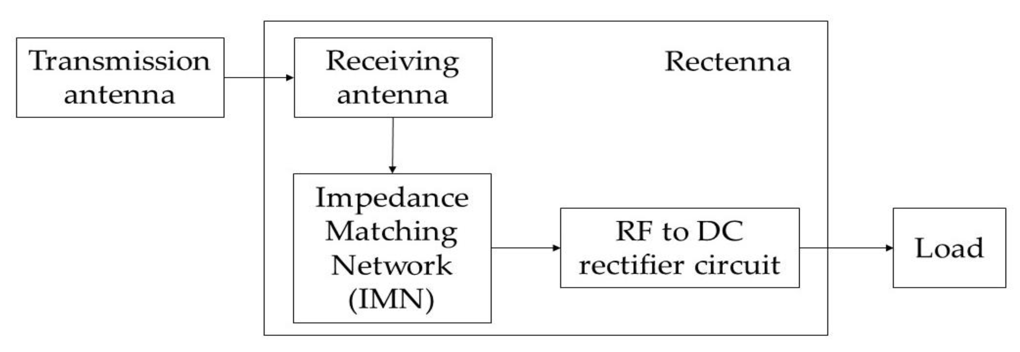
Figure 1. RF energy harvesting system [14].
Sensors 22 09712 g001
Figure 2. (a) Structural parameters of an SOI-based SSD, showing three main control factors: L, W, and Wt, and (b) the cross-section of the device [32].
Sensors 22 09712 g002
Figure 3. Comparison of IV characteristics between simulation and experimental data of Farhi et al. [32,35].
Sensors 22 09712 g003
Figure 4. The structural parameters of the SSD full wave bridge rectifier.
Sensors 22 09712 g004
Figure 5. The equivalent circuit for different biasing applied to the bridge rectifier in (a) positive cycle and (b) negative cycle.
Sensors 22 09712 g005
Figure 6. (a,b) The hole current density of the SOI SSD full wave bridge rectifier.
Sensors 22 09712 g006
Figure 7. I-V characteristics of the SSD full wave bridge rectifier.
Sensors 22 09712 g007
Figure 8. The AC signal inputs at (a) 1 GHz, (b) 5 GHz, (c) 10 GHz, and (d) 12 GHz with the rectified output DC current in (eh), respectively.
Sensors 22 09712 g008
Figure 9. Maximum output current, Iout.max from the rectified output DC current.
Sensors 22 09712 g009
Figure 10. Maximum output current Iout.max in various frequencies.
Sensors 22 09712 g010
Figure 11. Capacitance estimation of SSDBR.
Sensors 22 09712 g011
Figure 12. Structural parameters for estimation of channel capacitances, CSSD and trench capacitance, Ctrench.
Sensors 22 09712 g012
Table 2. Parameter values for each structural parameter of channel capacitances, CSSD and trench capacitance, Ctrench.
CapacitanceApplied Equation NoParameter Values
CSSD4a = 0.115 µm, b = 0.215 µm, c = 0.715 µm
6s = 2.0 µm, d = 0.10 µm
Ctrench4s = 1.63 µm, d = 0.10 µm
5s = 2.0 µm, d = 3.40 µm
Publisher’s Note: MDPI stays neutral with regard to jurisdictional claims in published maps and institutional affiliations.