
High-Resolution Detection of Rock-Forming Minerals by Permittivity Measurements with a Near-Field Scanning Microwave Microscope

 , , and
Abstract
:
1. Introduction
2. Materials and Methods
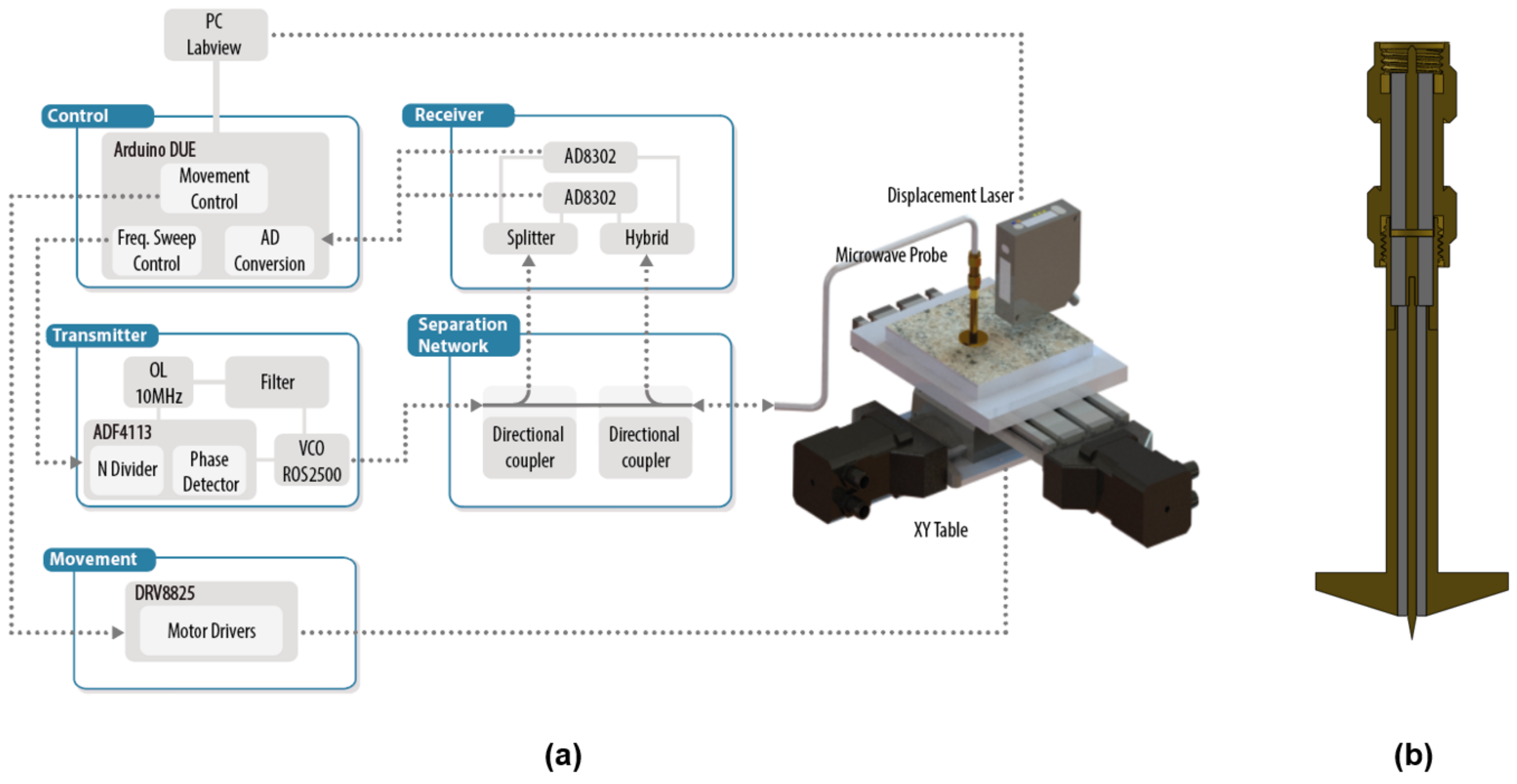
2.1. The Near-Field Microwave Microscope
2.2. Dielectric Characterization
2.3. Rock Samples
3. Experimental Results and Discussion
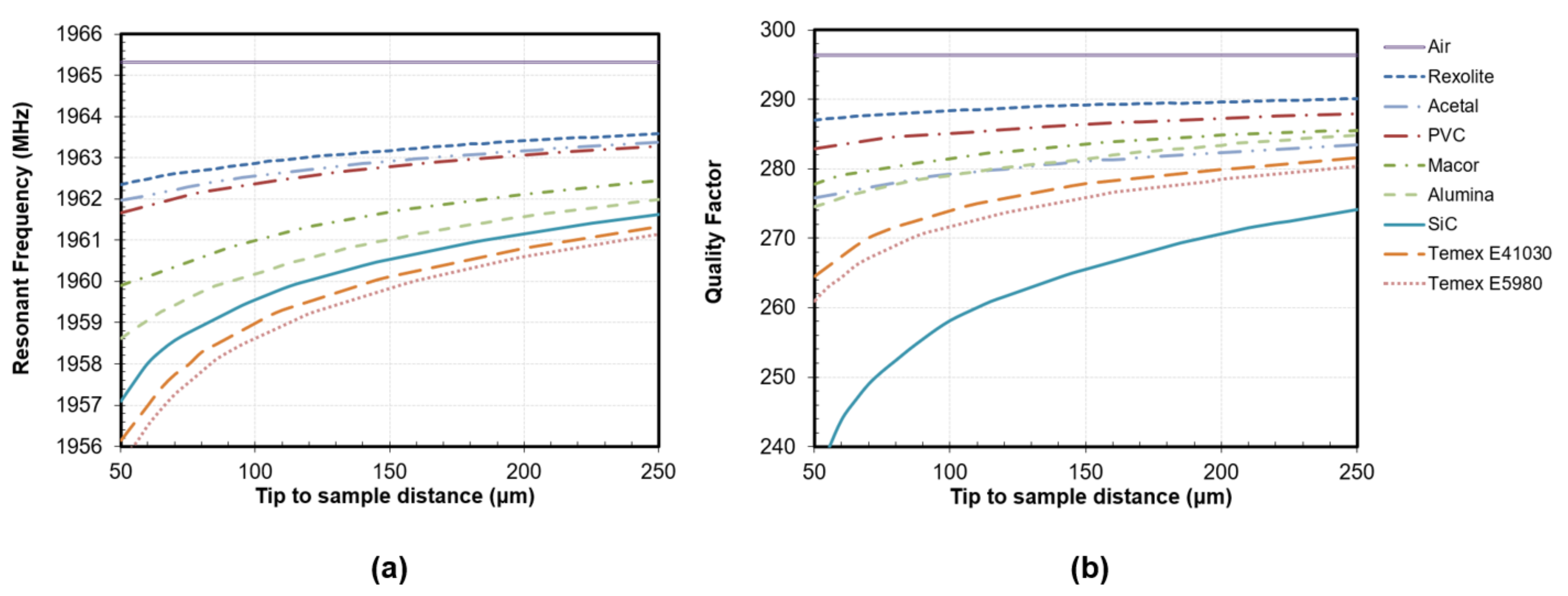
3.1. Dielectric Measurements of Reference Materials
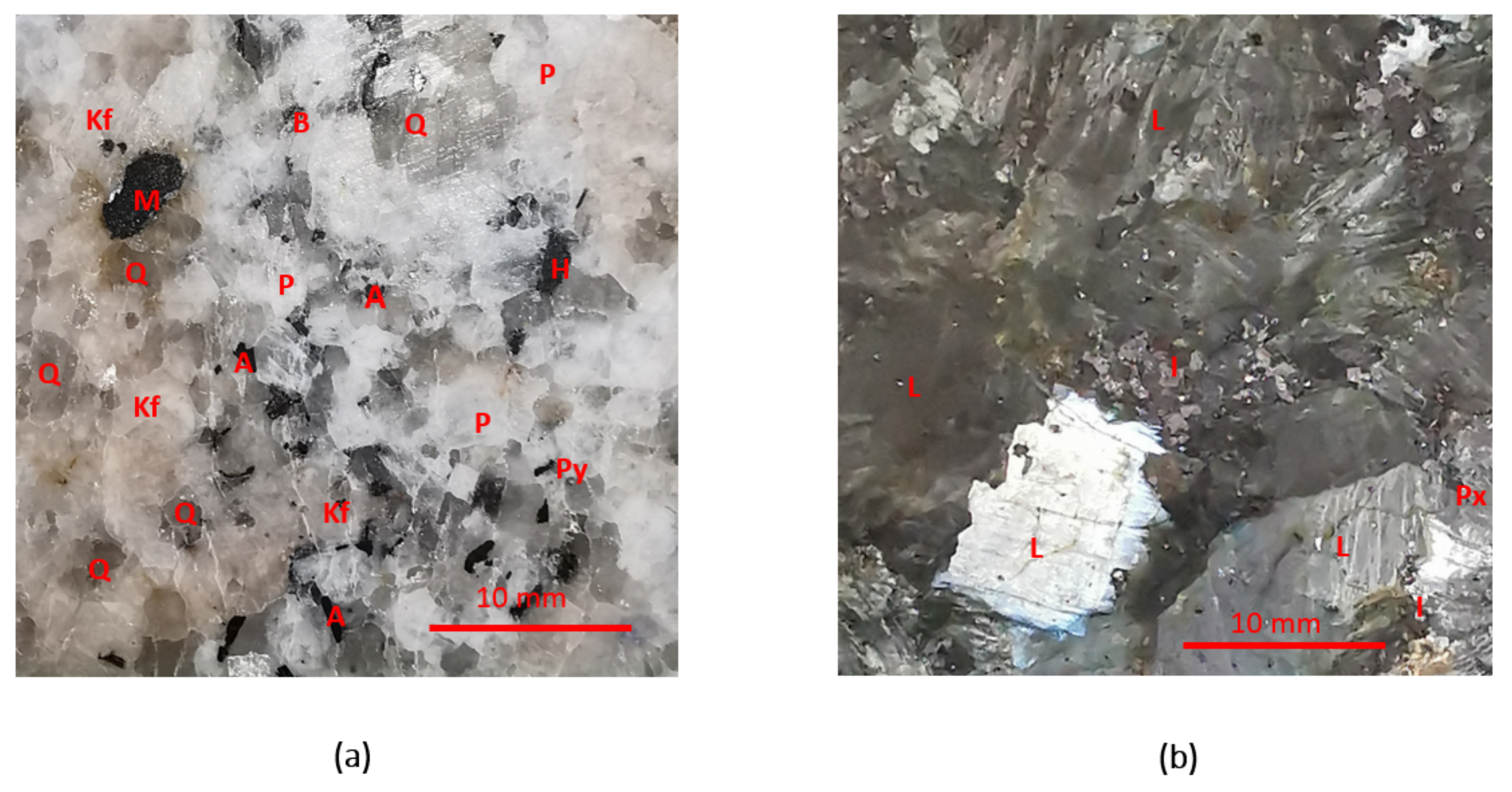
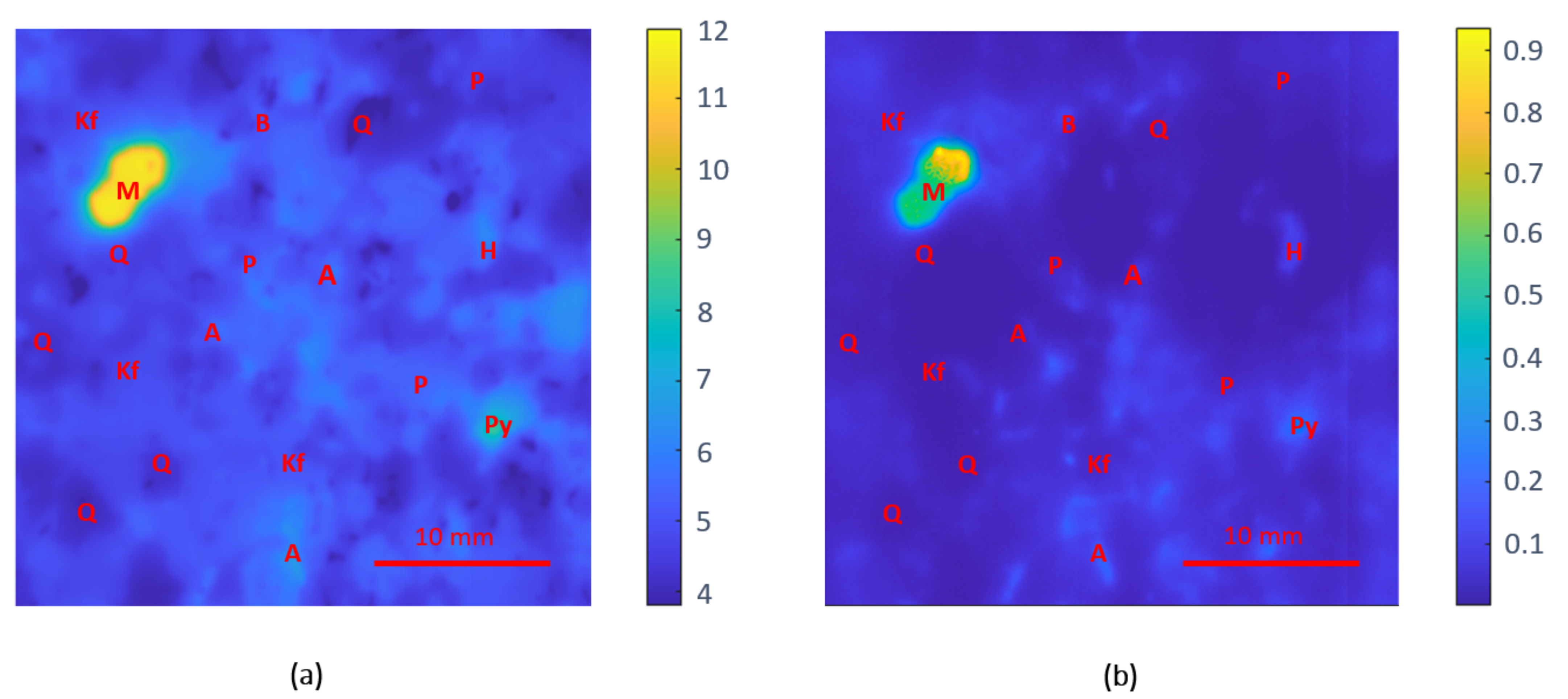
3.2. Permittivity Maps of Rock Specimens
3.2.1. Gneiss
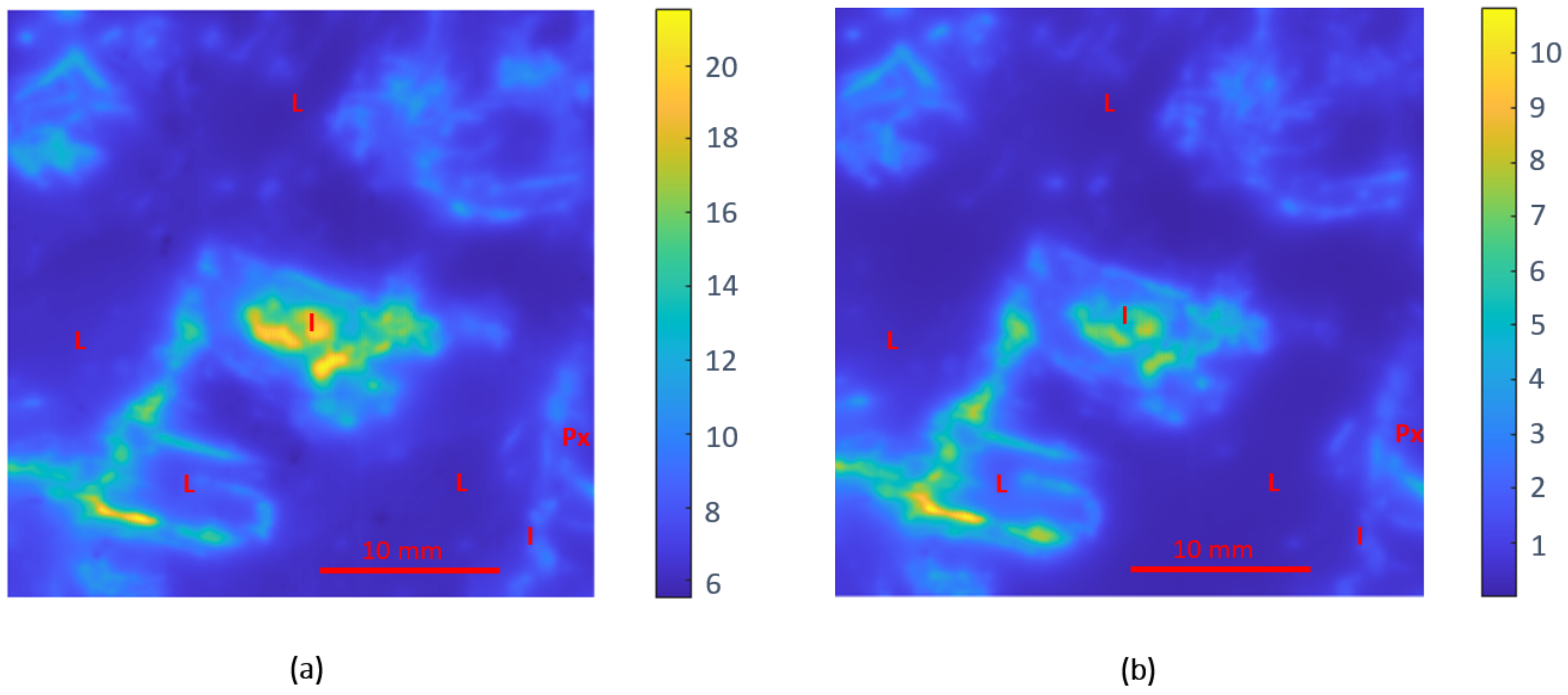
3.2.2. Anorthosite
4. Conclusions
Author Contributions
Funding
Institutional Review Board Statement
Informed Consent Statement
Conflicts of Interest
References
- Susilowati, Y.; Rahyuwibowo, H.; Mengko, T.R. Characteristic of interference color in rock forming mineral images. In Proceedings of the Asia-Pacific Conference on Circuits and Systems, APCCAS, Denpasar, Indonesia, 28–31 October 2002; Volume 2, pp. 265–268. [Google Scholar] [CrossRef]
- Povarov, V.G.; Kopylova, T.N.; Sinyakova, M.A.; Rudko, V.A. Quantitative determination of trace heavy metals and selected rock-forming elements in porous carbon materials by the X-ray fluorescence method. ACS Omega 2021, 6, 24595–24601. [Google Scholar] [CrossRef]
- Zhou, X.; Liu, D.; Bu, H.; Deng, L.; Liu, H.; Yuan, P.; Du, P.; Song, H. XRD-based quantitative analysis of clay minerals using reference intensity ratios, mineral intensity factors, Rietveld, and full pattern summation methods: A critical review. Solid Earth Sci. 2018, 3, 16–29. [Google Scholar] [CrossRef]
- Senesi, G.S. Laser-Induced Breakdown Spectroscopy (LIBS) applied to terrestrial and extraterrestrial analogue geomaterials with emphasis to minerals and rocks. Earth Sci. Rev. 2014, 139, 231–267. [Google Scholar] [CrossRef]
- El Haddad, J.; de Lima Filho, E.S.; Vanier, F.; Harhira, A.; Padioleau, C.; Sabsabi, M.; Wilkie, G.; Blouin, A. Multiphase mineral identification and quantification by laser-induced breakdown spectroscopy. Miner. Eng. 2019, 134, 281–290. [Google Scholar] [CrossRef]
- Lanari, P.; Vho, A.; Bovay, T.; Airaghi, L.; Centrella, S. Quantitative compositional mapping of mineral phases by electron probe micro-analyser. Geol. Soc. Spec. Publ. 2019, 478, 39–63. [Google Scholar] [CrossRef]
- Srivastava, P.K.; Krishna, A.P.; Jawed, S.; Sarkhel, P. Quantitative minerological analysis of some granite rocks of deoghar jharkhand. Earth Sci. Res. 2020, 9, 30. [Google Scholar] [CrossRef]
- Zhang, Y.; Li, M.; Han, S.; Ren, Q.; Shi, J. Intelligent identification for rock-mineral microscopic images using ensemble machine learning algorithms. Sensors 2019, 19, 3914. [Google Scholar] [CrossRef] [Green Version]
- Köse, C.; Alp, I.; Ikibaş, C. Statistical methods for segmentation and quantification of minerals in ore microscopy. Miner. Eng. 2012, 30, 19–32. [Google Scholar] [CrossRef]
- Aligholi, S.; Khajavi, R.; Razmara, M. Automated mineral identification algorithm using optical properties of crystals. Comput. Geosci. 2015, 85, 175–183. [Google Scholar] [CrossRef]
- Asmussen, P.; Conrad, O.; Günther, A.; Kirsch, M.; Riller, U. Semi-automatic segmentation of petrographic thin section images using a “seeded-region growing algorithm” with an application to characterize wheathered subarkose sandstone. Comput. Geosci. 2015, 83, 89–99. [Google Scholar] [CrossRef]
- Izadi, H.; Sadri, J.; Bayati, M. An intelligent system for mineral identification in thin sections based on a cascade approach. Comput. Geosci. 2017, 99, 37–49. [Google Scholar] [CrossRef]
- Liu, C.; Li, M.; Zhang, Y.; Han, S.; Zhu, Y. An enhanced rock mineral recognition method integrating a deep learning model and clustering algorithm. Minerals 2019, 9, 516. [Google Scholar] [CrossRef] [Green Version]
- Dąbrowska, S.; Chudoba, T.; Wojnarowicz, J.; Łojkowski, W. Current trends in the development of microwave reactors for the synthesis of nanomaterials in laboratories and industries: A review. Crystals 2018, 8, 379. [Google Scholar] [CrossRef] [Green Version]
- Priecel, P.; Lopez-Sanchez, J.A. Advantages and limitations of microwave reactors: From chemical synthesis to the catalytic valorization of biobased chemicals. ACS Sustain. Chem. Eng. 2019, 7, 3–21. [Google Scholar] [CrossRef] [Green Version]
- Llompart, M.; Celeiro, M.; Dagnac, T. Microwave-assisted extraction of pharmaceuticals, personal care products and industrial contaminants in the environment. TrAC Trends Anal. Chem. 2019, 116, 136–150. [Google Scholar] [CrossRef]
- Wei, W.; Shao, Z.; Zhang, Y.; Qiao, R.; Gao, J. Fundamentals and applications of microwave energy in rock and concrete processing—A review. Appl. Therm. Eng. 2019, 157, 113751. [Google Scholar] [CrossRef]
- Kahraman, S.; Canpolat, A.N.; Fener, M. The influence of microwave treatment on the compressive and tensile strength of igneous rocks. Int. J. Rock Mech. Min. Sci. 2020, 129, 104303. [Google Scholar] [CrossRef]
- Lu, G.M.; Feng, X.T.; Li, Y.H.; Zhang, X. The microwave-induced fracturing of hard rock. Rock Mech. Rock Eng. 2019, 52, 3017–3032. [Google Scholar] [CrossRef]
- Wang, J.P.; Jiang, T.; Liu, Y.J.; Xue, X.X. Influence of microwave treatment on grinding and dissociation characteristics of vanadium titano-magnetite. Int. J. Miner. Metall. Mater. 2019, 26, 160–167. [Google Scholar] [CrossRef]
- Guo, L.; Lan, J.; Du, Y.; Zhang, T.C.; Du, D. Microwave-enhanced selective leaching of arsenic from copper smelting flue dusts. J. Hazard. Mater. 2020, 386, 121964. [Google Scholar] [CrossRef]
- López-Buendía, A.M.; Guillem, C.; Cuevas, J.M.; Mateos, F.; Montoto, M. Natural stone reinforcement of discontinuities with resin for industrial processing. Eng. Geol. 2013, 166, 39–51. [Google Scholar] [CrossRef]
- Krupka, J. Frequency domain complex permittivity measurements at microwave frequencies. Meas. Sci. Technol. 2006, 17, R55–R70. [Google Scholar] [CrossRef]
- García-Baños, B.; Cuesta-Soto, F.; Griol, A.; Catalá-Civera, J.M.; Pitarch, J. Enhancement of sensitivity of microwave planar sensors with EBG structures. IEEE Sens. J. 2006, 6, 1518–1522. [Google Scholar] [CrossRef]
- Pitarch, J.; Contelles-Cervera, M.; Pẽaranda-Foix, F.L.; Catalá-Civera, J.M. Determination of the permittivity and permeability for waveguides partially loaded with isotropic samples. Meas. Sci. Technol. 2006, 17, 145–152. [Google Scholar] [CrossRef]
- Pérez-Campos, R.; Fayos-Fernández, J.; Lozano-Guerrero, A.J.; Martínez-González, A.; Monzó-Cabrera, J.; Mediavilla, I.; Peña-Carro, D.; Esteban-Pascual, L.S. Permittivity measurements for cypress and rockrose biomass versus temperature, density, and moisture content. Sensors 2020, 20, 4684. [Google Scholar] [CrossRef]
- Neira, L.M.; Mays, R.O.; Sawicki, J.F.; Schulman, A.; Harter, J.; Wilke, L.G.; Behdad, N.; Van Veen, B.D.; Hagness, S.C. A pilot study of the impact of microwave ablation on the dielectric properties of breast tissue. Sensors 2020, 20, 5698. [Google Scholar] [CrossRef]
- González-Teruel, J.D.; Jones, S.B.; Soto-Valles, F.; Torres-Sánchez, R.; Lebron, I.; Friedman, S.P.; Robinson, D.A. Dielectric spectroscopy and application of mixing models describing dielectric dispersion in clay minerals and clayey soils. Sensors 2020, 20, 6678. [Google Scholar] [CrossRef]
- Oliveira, J.G.D.; Junior, J.G.D.; Pinto, E.N.M.G.; Neto, V.P.S.; D’Assunção, A.G. A new planar microwave sensor for building materials complex permittivity characterization. Sensors 2020, 20, 6328. [Google Scholar] [CrossRef]
- Gutierrez-Cano, J.D.; Plaza-Gonzalez, P.; Canos, A.J.; Garcia-Banos, B.; Catala-Civera, J.M.; Penaranda-Foix, F.L. A new stand-alone microwave instrument for measuring the complex permittivity of materials at microwave frequencies. IEEE Trans. Instrum. Meas. 2020, 69, 3595–3605. [Google Scholar] [CrossRef]
- Lu, G.; Zhou, J.; Li, Y.; Zhang, X.; Gao, W. The influence of minerals on the mechanism of microwave-induced fracturing of rocks. J. Appl. Geophys. 2020, 180, 104123. [Google Scholar] [CrossRef]
- Deyab, S.M.; Rafezi, H.; Hassani, F.; Kermani, M.; Sasmito, A.P. Experimental investigation on the effects of microwave irradiation on kimberlite and granite rocks. J. Rock Mech. Geotech. Eng. 2021, 13, 267–274. [Google Scholar] [CrossRef]
- Lovás, M.; Kováčová, M.; Dimitrakis, G.; Čuvanová, S.; Znamenáčková, I.; Jakabský, Š. Modeling of microwave heating of andesite and minerals. Int. J. Heat Mass Transf. 2010, 53, 3387–3393. [Google Scholar] [CrossRef]
- Pittella, E.; Angrisani, L.; Cataldo, A.; Piuzzi, E.; Fabbrocino, F. Embedded split ring resonator network for health monitoring in concrete structures. IEEE Instrum. Meas. Mag. 2020, 23, 14–20. [Google Scholar] [CrossRef]
- D’Alvia, L.; Pittella, E.; Rizzuto, E.; Piuzzi, E.; Del Prete, Z. A portable low-cost reflectometric setup for moisture measurement in cultural heritage masonry unit. Meas. J. Int. Meas. Confed. 2021, 189, 110438. [Google Scholar] [CrossRef]
- Zheng, Y.L.; Zhao, X.B.; Zhao, Q.H.; Li, J.C.; Zhang, Q.B. Dielectric properties of hard rock minerals and implications for microwave-assisted rock fracturing. Geomech. Geophys. Geo-Energy Geo-Resour. 2020, 6, 1–17. [Google Scholar] [CrossRef]
- Zheng, Y.; Sun, T. A method to derive the dielectric loss factor of minerals from microwave heating rate tests. Meas. J. Int. Meas. Confed. 2021, 171, 108788. [Google Scholar] [CrossRef]
- Anlage, S.M.; Talanov, V.V.; Schwartz, A.R. Principles of near-field microwave microscopy. In Scanning Probe Microscopy: Electrical and Electromechanical Phenomena at the Nanoscale; Kalinin, S., Gruverman, A., Eds.; Springer: New York, NY, USA, 2007; pp. 215–253. ISBN 978-0-387-28668-6. [Google Scholar]
- Vlahacos, C.P.; Black, R.C.; Anlage, S.M.; Amar, A.; Wellstood, F.C. Near-field scanning microwave microscope with 100 μm resolution. Appl. Phys. Lett. 1996, 69, 3272–3274. [Google Scholar] [CrossRef]
- Gregory, A.P.; Blackburn, J.F.; Lees, K.; Clarke, R.N.; Hodgetts, T.E.; Hanham, S.M.; Klein, N. Measurement of the permittivity and loss of high-loss materials using a Near-Field Scanning Microwave Microscope. Ultramicroscopy 2016, 161, 137–145. [Google Scholar] [CrossRef] [Green Version]
- Ramzi, M.R.; Abou-Khousa, M.; Prayudi, I. Near-field microwave imaging using open-ended circular waveguide probes. IEEE Sens. J. 2017, 17, 2359–2366. [Google Scholar] [CrossRef]
- Xie, Z.; Li, Y.; Sun, L.; Wu, W.; Cao, R.; Tao, X. A simple high-resolution near-field probe for microwave non-destructive test and imaging. Sensors 2020, 20, 2670. [Google Scholar] [CrossRef]
- Imtiaz, A.; Wallis, T.M.; Kabos, P. Near-field scanning microwave microscopy: An emerging research tool for nanoscale metrology. IEEE Microw. Mag. 2014, 15, 52–64. [Google Scholar] [CrossRef]
- Paulson, C.A.; Van Der Weide, D.W. Near-field high-frequency probing. In Scanning Probe Microscopy; Kalinin, S., Gruverman, A., Eds.; Springer: New York, NY, USA, 2007; pp. 315–345. ISBN 978-0-387-28668-6. [Google Scholar]
- Tabib-Azar, M.; Zhang, T.; LeClair, S.R. Self-oscillating evanescent microwave probes for nondestructive evaluations of materials. IEEE Trans. Instrum. Meas. 2002, 51, 1126–1132. [Google Scholar] [CrossRef]
- Wu, B.Y.; Sheng, X.Q.; Fabregas, R.; Hao, Y. Full-wave modeling of broadband near field scanning microwave microscopy. Sci. Rep. 2017, 7, 16064. [Google Scholar] [CrossRef] [PubMed] [Green Version]
- Gao, C.; Xiang, X.D. Quantitative microwave near-field microscopy of dielectric properties. Rev. Sci. Instrum. 1998, 69, 3846–3851. [Google Scholar] [CrossRef]
- Gao, C.; Hu, B.; Takeuchi, I.; Chang, K.S.; Xiang, X.D.; Wang, G. Quantitative scanning evanescent microwave microscopy and its applications in characterization of functional materials libraries. Meas. Sci. Technol. 2005, 16, 248–260. [Google Scholar] [CrossRef]
- Cheng, H.F.; Chen, Y.C.; Lin, I.N. Evanescent microwave probe study on dielectric properties of materials. J. Eur. Ceram. Soc. 2006, 26, 1801–1805. [Google Scholar] [CrossRef]
- Kimber, D.P.; Pullar, R.C.; Alford, N.M.N. The effects of dielectric loss and tip resistance on resonator Q of the scanning evanescent microwave microscopy (SEMM) probe. Meas. Sci. Technol. 2008, 19, 2–6. [Google Scholar] [CrossRef]
- Geaney, S.; Cox, D.; Hönigl-Decrinis, T.; Shaikhaidarov, R.; Kubatkin, S.E.; Lindström, T.; Danilov, A.V.; de Graaf, S.E. Near-field scanning microwave microscopy in the single photon regime. Sci. Rep. 2019, 9, 12539. [Google Scholar] [CrossRef]
- Tselev, A.; Yu, P.; Cao, Y.; Dedon, L.R.; Martin, L.W.; Kalinin, S.V.; Maksymovych, P. Microwave a.c. conductivity of domain walls in ferroelectric thin films. Nat. Commun. 2016, 7, 11630. [Google Scholar] [CrossRef] [Green Version]
- Gangwar, A.K.; Kanika; Kedawat, G.; Papanai, G.S.; Gupta, B.K. Single excitable dual emissive novel luminescent pigment to generate advanced security features for anti-counterfeiting applications. J. Mater. Chem. C 2019, 7, 13867–13877. [Google Scholar] [CrossRef]
- Tai, T.; Ghamsari, B.G.; Bieler, T.R.; Tan, T.; Xi, X.X.; Anlage, S.M. Near-field microwave magnetic nanoscopy of superconducting radio frequency cavity materials. Appl. Phys. Lett. 2014, 104, 6–10. [Google Scholar] [CrossRef] [Green Version]
- Hoffmann, J.; Gramse, G.; Niegemann, J.; Zeier, M.; Kienberger, F. Measuring low loss dielectric substrates with scanning probe microscopes. Appl. Phys. Lett. 2014, 105, 1–5. [Google Scholar] [CrossRef]
- Farina, M.; Jin, X.; Fabi, G.; Pavoni, E.; Di Donato, A.; Mencarelli, D.; Morini, A.; Piacenza, F.; Al Hadi, R.; Zhao, Y.; et al. Inverted scanning microwave microscope for in vitro imaging and characterization of biological cells. Appl. Phys. Lett. 2019, 114, 8–11. [Google Scholar] [CrossRef] [Green Version]
- Monti, T.; Tselev, A.; Udoudo, O.; Ivanov, I.N.; Dodds, C.; Kingman, S.W. High-resolution dielectric characterization of minerals: A step towards understanding the basic interactions between microwaves and rocks. Int. J. Miner. Process. 2016, 151, 8–21. [Google Scholar] [CrossRef] [Green Version]
- Gutiérrez-Cano, J.D.; Catalá-Civera, J.M.; Plaza-González, P.J.; Peñaranda-Foix, F.L. Detection of anti-counterfeiting markers through permittivity maps using a micrometer scale near field scanning microwave microscope. Sensors 2021, 21, 5463. [Google Scholar] [CrossRef]
- Caja, M.Á.; Peña, A.C.; Campos, J.R.; Diego, L.G.; Tritlla, J.; Bover-Arnal, T.; Martín-Martín, J.D. Image processing and machine learning applied to lithology identification, classification and quantification of thin section cutting samples. In Proceedings of the SPE Annual Technical Conference and Exhibition, Calgary, AL, Canada, 30 September–2 October 2019. [Google Scholar] [CrossRef]
- Acosta, I.C.C.; Khodadadzadeh, M.; Tusa, L.; Ghamisi, P.; Gloaguen, R. A Machine learning framework for drill-core mineral mapping using hyperspectral and high-resolution mineralogical data fusion. IEEE J. Sel. Top. Appl. Earth Obs. Remote Sens. 2019, 12, 4829–4842. [Google Scholar] [CrossRef]
- Harraden, C.L.; Cracknell, M.J.; Lett, J.; Berry, R.F.; Carey, R.; Harris, A.C. Automated core logging technology for geotechnical assessment: A study on core from the Cadia East porphyry deposit. Econ. Geol. 2019, 114, 1495–1511. [Google Scholar] [CrossRef]
- Metaxas, A.C. Microwave heating. Power Eng. J. 1991, 5, 237–247. [Google Scholar] [CrossRef]
- Kajfez, D. Linear fractional curve fitting for measurement of high Q factors. IEEE Trans. Microw. Theory Tech. 1994, 42, 1149–1153. [Google Scholar] [CrossRef]
- Kajfez, D. Q-Factor; Vector Fields: Oxford, MS, USA, 1994. [Google Scholar]
- Kleismit, R.A.; Kazimierczuk, M.K.; Kozlowski, G. Sensitivity and resolution of evanescent microwave microscope. IEEE Trans. Microw. Theory Tech. 2006, 54, 1–9. [Google Scholar] [CrossRef]
- Altschuler, H.M. Dielectric constant. In Handbook of Microwave Measurements; Sucher, M., Fox, J., Eds.; Polytechic Institute Brooklyn Press: New York, NY, USA, 1963. [Google Scholar]
- Khanna, S.K.; Ehrenfreund, E.; Garito, A.F.; Heeger, A.J. Microwave properties of high-purity tetrathiofulvalene-tetracyanoquinodimethan (TTF-TCNQ). Phys. Rev. B 1974, 10, 2205–2220. [Google Scholar] [CrossRef]
- Mao, W.; Wu, L.; Qi, Y. Impact of compressive stress on microwave dielectric properties of feldspar dpecimen. IEEE Trans. Geosci. Remote Sens. 2020, 58, 1398–1408. [Google Scholar] [CrossRef]
- Zheng, Y.; Wang, S.; Feng, J.; Ouyang, Z.; Li, X. Measurement of the complex permittivity of dry rocks and minerals: Application of polythene dilution method and Lichtenecker’s mixture formulae. Geophys. J. Int. 2005, 163, 1195–1202. [Google Scholar] [CrossRef] [Green Version]
- Church, R.H.; Webb, W.E.; Salsman, J.B. Dielectric Properties of Low-Loss Minerals; US Department of the Interior: Washington, DC, USA, 1988; Volume 9194.
- Nelson, S.; Lindroth, D.; Blake, R. Dielectric properties of selected and purified minerals at 1 to 22 GHz. J. Microw. Power Electromagn. Energy 1989, 24, 213–220. [Google Scholar] [CrossRef]
- Harrison, P.C. A Fundamental Study of the Heating Effect of 2.45 GHz Microwave Radiation on Minerals; University of Birmingham: Birmingham, UK, 1997. [Google Scholar]
- Zhang, B.; Yan, G.; Zhao, Y.; Zhou, C.; Lu, Y. Coal pyrite microwave magnetic strengthening and electromagnetic response in magnetic separation desulfurization process. Int. J. Miner. Process. 2017, 168, 136–142. [Google Scholar] [CrossRef]
- Penaranda-Foix, F.L.; Janezic, M.D.; Catala-Civera, J.M.; Canos, A.J. Full-wave analysis of dielectric-loaded cylindrical waveguides and cavities using a new four-port ring network. IEEE Trans. Microw. Theory Tech. 2012, 60, 2730–2740. [Google Scholar] [CrossRef]
- Duarte, F.A.; Waechter, S.R.; Pedrotti, M.F.; Pardinho, R.B.; Flores, E.M.M.; Barin, J.S. Microwave-induced combustion in disposable vessels: A novel perspective for sample digestion. Anal. Chem. 2020, 92, 8058–8063. [Google Scholar] [CrossRef] [PubMed]
- Lu, G.-M.; Li, Y.-H.; Hassani, F.; Zhang, X. The influence of microwave irradiation on thermal properties of main rock-forming minerals. Appl. Therm. Eng. 2017, 112, 1523–1532. [Google Scholar] [CrossRef]
- Pandey, C.S.; Jodlauk, S.; Schreuer, J. Correlation between dielectric properties and chemical composition of the tourmaline single crystals. Appl. Phys. Lett. 2011, 99, 6–9. [Google Scholar] [CrossRef]


| Material | Frequency (GHz) | Permittivity | Reference |
|---|---|---|---|
| k-Feldspars | 2.00 | 5.18-j0.023 | [68] |
| 9.37 | 5.12-j0.011 | [69] | |
| 9.37 | 4.75-j0.044 | [69] | |
| Biotite | 1.00 | 5.9-j0.002 | [70] |
| Plagioclase (Labradorite) | 2.45 | 6.01-j0.09 | [71] |
| Plagioclase | 2.45 | 3.49-j0.020 | [37] |
| Plagioclase (albite) | 2.45 | 5.62-j0.039 | [36] |
| Pyroxene (augite) | 2.45 | 6.80-j0.182 | [36] |
| Hornblende | 2.45 | 14.45-j0.324 | [36] |
| 2.45 | 8.91-j0.233 | [37] | |
| 2.45 | 7.37-j0.026 | [71] | |
| Magnetite | 2.45 | 14.5-j2.5 | [72] |
| Pyrite (Shanxi Lu′an) | 2.45 | 8-j0.75 | [73] |
| Ilmenite | 2.45 | 3.75-j0.24 | [72] |
| 2.45 | 23.6-j11.2 | [71] |
| Material | Dielectric Constant | Loss Factor | ||||||||||||
|---|---|---|---|---|---|---|---|---|---|---|---|---|---|---|
| g (µm) | Mean | Std Dev | Reference | Error (%) | g (µm) | Mean | Std Dev | Reference | Error (%) | |||||
| 100 | 150 | 200 | 100 | 150 | 200 | |||||||||
| Air | 1.00 | 1.00 | 1.00 | 1.00 | 0.00 | 1.00 | 0.00 | 0.000 | 0.000 | 0.000 | 0.000 | 0.000 | 0.000 | 0.00 |
| Rexolite | 2.55 | 2.57 | 2.57 | 2.56 | 0.01 | 2.53 ± 0.05 | 1.23 | 0.000 | 0.002 | 0.007 | 0.003 | 0.003 | 0.001 ± 0.000 | >10 |
| Acetal | 2.88 | 2.90 | 2.92 | 2.90 | 0.02 | 2.96 ± 0.05 | 2.06 | 0.105 | 0.113 | 0.123 | 0.114 | 0.009 | 0.120 ± 0.006 | 5.65 |
| PVC | 3.09 | 3.07 | 3.12 | 3.09 | 0.03 | 3.09 ± 0.06 | 0.11 | 0.024 | 0.027 | 0.031 | 0.027 | 0.004 | 0.025 ± 0.001 | 9.75 |
| Macor | 5.69 | 5.63 | 5.66 | 5.66 | 0.03 | 5.68 ± 0.11 | 0.35 | 0.020 | 0.026 | 0.031 | 0.026 | 0.005 | 0.024 ± 0.001 | 7.44 |
| Alumina | 8.97 | 9.10 | 8.93 | 9.00 | 0.09 | 8.94 ± 0.18 | 0.68 | 0.012 | 0.025 | 0.020 | 0.019 | 0.006 | 0.006 ± 0.000 | >10 |
| SiC | 14.53 | 14.74 | 14.69 | 14.66 | 0.11 | 14.53 ± 0.41 | 2.20 | 2.134 | 2.077 | 2.128 | 2.113 | 0.031 | 2.092 ± 0.105 | 1.09 |
| Temex E41030 | 29.19 | 28.32 | 29.56 | 29.02 | 0.64 | 28.28 ± 0.56 | 2.63 | 0.068 | 0.000 | 0.130 | 0.066 | 0.065 | 0.001 ± 0.000 | >10 |
| Temex E5980 | 69.88 | 72.19 | 65.79 | 69.28 | 3.24 | 67.25 ± 1.34 | 3.02 | 0.000 | 0.000 | 1.014 | 0.338 | 0.585 | 0.018 ± 0.006 | >10 |
Publisher’s Note: MDPI stays neutral with regard to jurisdictional claims in published maps and institutional affiliations. |
© 2022 by the authors. Licensee MDPI, Basel, Switzerland. This article is an open access article distributed under the terms and conditions of the Creative Commons Attribution (CC BY) license (https://creativecommons.org/licenses/by/4.0/).
Share and Cite
Gutiérrez-Cano, J.D.; Catalá-Civera, J.M.; López-Buendía, A.M.; Plaza-González, P.J.; Penaranda-Foix, F.L. High-Resolution Detection of Rock-Forming Minerals by Permittivity Measurements with a Near-Field Scanning Microwave Microscope. Sensors 2022, 22, 1138. https://doi.org/10.3390/s22031138
Gutiérrez-Cano JD, Catalá-Civera JM, López-Buendía AM, Plaza-González PJ, Penaranda-Foix FL. High-Resolution Detection of Rock-Forming Minerals by Permittivity Measurements with a Near-Field Scanning Microwave Microscope. Sensors. 2022; 22(3):1138. https://doi.org/10.3390/s22031138
Chicago/Turabian StyleGutiérrez-Cano, José D., José M. Catalá-Civera, Angel M. López-Buendía, Pedro J. Plaza-González, and Felipe L. Penaranda-Foix. 2022. "High-Resolution Detection of Rock-Forming Minerals by Permittivity Measurements with a Near-Field Scanning Microwave Microscope" Sensors 22, no. 3: 1138. https://doi.org/10.3390/s22031138
APA StyleGutiérrez-Cano, J. D., Catalá-Civera, J. M., López-Buendía, A. M., Plaza-González, P. J., & Penaranda-Foix, F. L. (2022). High-Resolution Detection of Rock-Forming Minerals by Permittivity Measurements with a Near-Field Scanning Microwave Microscope. Sensors, 22(3), 1138. https://doi.org/10.3390/s22031138