1. Introduction
Fourier lightfield microscopy (FLMic) [
1,
2,
3,
4] is a reformulation of lightfield microscopy (LMic) [
5,
6,
7,
8,
9,
10,
11] featuring the capacity of capturing directly, in a single shot, a collection of orthographic perspective images of 3D specimens. Due to the linear and spatially shift-invariant nature of captured views, FLMic is especially suited for easing the postprocessing and therefore for providing depth reconstructions with high and homogeneous resolution over a large depth of field [
12,
13,
14,
15]. Despite the short amount of time that has passed since FLMic was first reported [
1], the number of applications for capturing dynamic biomedical images has increased significantly [
16,
17,
18,
19,
20,
21]. The FLMic can be built from scratch by aligning and adjusting many different elements, such as the illumination system, the sample holder, an infinity-corrected microscope objective (MO), the tube lens, relay lenses, the microlens array (MLA), and a digital camera. An attractive alternative is to build a Fourier lightfield accessory designed to be inserted at the camera port of a microscope [
22]. In any case, the resulting FLMic can be somehow bulky, and with a final cost equal to several thousand dollars. Perhaps this fact has concealed the advantages of FLMic, and delayed the spread of the Fourier lightfield concept, which is potentially suited to application to image in-field sample volumes; for instance, living phytoplankton [
22], zebrafish embryos [
23], neuronal activity [
24], and other potential applications such as microplastic screening, food processing chains, colloidal stability in material industries, amongst others.
With the aim of overcoming this bottleneck, in this paper we report the method of producing a compact, robust, reliable, and affordable FLMic. Thus, a hand-held and cost-effective FLMic was designed, built, and tested. In fact, we took profit of a new trend in microscopy: the design and production of low-cost miniscopes [
25,
26,
27,
28,
29,
30,
31]. Following this trend an FLMic was designed with use of very affordable hardware without jeopardizing the optical performance. The resulting FLMic has a weight under the 400 g, reduced volume, and a cost that can be at least 100 times lower than that of a regular FLMic.
2. Materials and Methods
The FLMic design is based on two conjugation relations and on the key role played by two hard apertures. In summary, the MLA is virtually inserted, with the help of a telecentric optical relay, at the aperture stop of an infinity-corrected MO. This adjustment ensures that any microlens captures an orthographic perspective image of the 3D sample—usually named as the elemental image (EI). The number of microlenses that are fitted in the aperture stop of the MO equals the number of recorded EIs, from which the posterior digital processing allows the refocusing of the 3D sample volume. Additionally, a second hard stop is set in a plane between the lenses of the relay, so that it is conjugated with the object plane, and also with the pixelated sensor, which is set at the rear focal plane of the microlenses. The task of this second stop is to avoid overlapping between EIs, and therefore to fix the field of view (FOV) of the microscope. Thus, it is acting as the field stop.
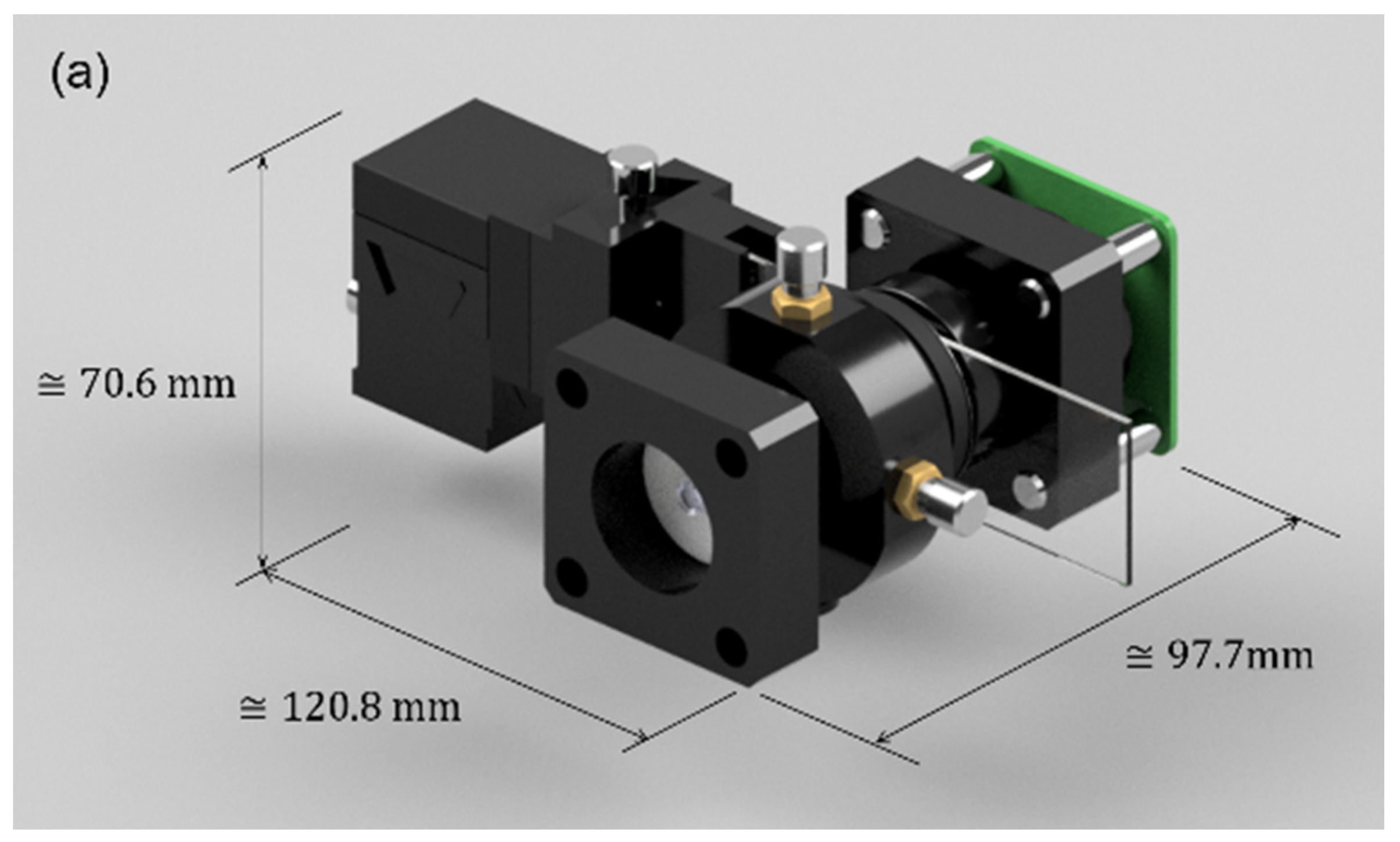
The usual hardware setup makes the FLMic a somehow bulky device, the price of which can easily reach USD 1000, limiting its widespread use in terms of portability and cost. For these reasons, this works presents an easy-to-build, handheld, and cost-effective FLMic, whose 3D-render model is shown in
Figure 1. In panel (a), the 3D model of the handheld and cost-effective lightfield microscope is shown. From this panel, the reader can see the physical dimensions that support the claim of handheld; the illumination system and the cover slide manipulation stage are included in the drawing. In panel (b), an exploded drawing where the components of the microscope and their assembly are presented. The LED is the main component of the illumination system; the field stop is illustrated in the alignment stage and the sample is also drawn with its corresponding manipulation stage.
As a proposal to build a compact and cost-effective FLMic, we focused on two main points: (i) the use of imaging lenses with optical performance roughly similar to that of an infinity-corrected MO, but some orders of magnitude less costly; and (ii) the determination of a method of removing the relay lenses and the corresponding field stop. To accomplish the point (i) we chose, as strong candidates, the M12 lenses typically used in surveillance cameras. These lenses, which have a short focal length, were originally designed for providing aberration-compensated images of far and large scenes. Interestingly, this means that by simply inverting the light-rays trajectory, the M12 lenses can be used for producing at the infinity the aberration-compensated image of a microscopic sample, provided it is placed at the M12 focal plane. In this sense, the inverted M12 lenses behaves in the same way as an infinity-corrected MO. Thanks to their mass production, these lenses have a cost that is at least two-orders of magnitude lower than an optically equivalent infinity-corrected MO [
32]. Naturally, the main concern for using this configuration is the presence of optical aberrations in the image plane that could ruin the performance of the proposed FLMic. However, as it will be discussed in
Section 3, the aberration impact is low, allowing the overall performance of the proposed FLMic to be quite competitive.
The challenge of point (ii) is twofold. It is necessary to find a method of placing the MLA at the exit pupil of the M12 lens and also a method of inserting a field stop to prevent the overlapping between EIs. Despite the fact that apparently there is no available technical information on the M12 optical design, we found experimentally that the exit pupil of said lens is close to its outermost surface. This means that placing the by MLA in close contact with the M12 lens, the former is in the proximity of the exit pupil. The consequence of not locating the MLA exactly at the MO exit pupil is not a reduction in the optical quality of the captured EIs, but the introduction of some vignetting in the outermost EIs. The field-stop problem is solved here by placing a diaphragm just at the sample plane. In other words, only the required FOV is illuminated. This hard stop behaves indeed as the effective entrance window, which seen from the image plane is therefore the field stop of the FLMic. Thus, its size must be chosen in such a way that the FOV of the FLMic is maximized, namely, allowing the EIs to be tangent to each other. It is important to place this diaphragm in close contact to the sample to ensure that both are in focus, that is, they lay within the depth of field (DOF).
The choice of the digital camera must also follow the cost-effective philosophy of the proposed FLMic. Fortunately, the mass production for diverse purposes has made available very competitive digital cameras with prices that are very accessible. Because of its great versatility and attractive tradeoff between price and performance, in this work the HQ Raspberry-Pi Camera was selected.
In overall, while the replacement of the infinity-corrected MO by the M12 lens guarantees the cost-effectiveness of the system, the elimination of the relay lens and the relocation of the field stop secures the compactness and portability of the resulting microscope, which articulated with the HQ Raspberry-Pi Camera turns the designed FLMic into a very competitive device, as shown in the following sections. Raspberry Pi can be powered by regular off-the-shelf batteries. It needs a power supply of voltage 5.1 V while the recommended capacity depends on the model. Depending on the model, it can be powered via Micro USB or USB-C. Therefore, having the right connector, a power bank or a solar cell can be used to supply the Raspberry Pi. To visualize the captured EIs and reconstructed images, a HDMI monitor is also necessary or the capabilities of the Raspberry Pi can even be used to send information to a mobile phone, to use it as a display.
2.1. Design Parameters
The design and build of the FLMic illustrated in
Figure 1 followed the equation and process of design formerly reported in [
2,
4]. In these references, all the details and governing equations can be found. However, they are adapted here to the new situation in which the relay is not used.
The first parameter to control is the spatial resolution of the handheld FLMic. The lateral resolution limit of the directly captured EIs, strictly understood as the capability of resolving two equally emitting incoherent light points separated a distance
in the object space, is given by sum of the diffractive
and geometric
factors. It is given by:
In Equation (1),
N is the number of microlenses fitted within the aperture stop of the MO,
the illuminating wavelength, and
NA the numerical aperture of the MO. Besides,
is the total magnification of the FLMic, being
and
the focal length of the MLA and the M12 lens, respectively. Finally,
is the pixel pitch of the digital camera.
For the selected M12 lenses
NA = 0.2, hence, a small angle approximation can be utilized to compute the number
N:
with
p the pitch of the MLA. The value of
N must be chosen to be between 3 and 5 to have enough EIs to compute the refocused images while the spatial resolution is not too penalized, even though other choices of
N are feasible if required.
To ensure that the EIs are tangent to each other over the digital sensor, the size of the image of the field stop must match the value of
p. As for the proposed handheld FLMic the field stop is in contact with the sample plane, the reachable
FOV is equal to the field-stop diameter,
, which is then given by:
Finally, the
DOF of the proposed handheld lightfield microscope is also the result of the entanglement of the diffractive and the geometrical factors. Accordingly, the
DOF yields:
2.2. Design Workflow
The use of the M12 lens as infinity-corrected MO, dictates the working
NA = 0.2 reported by the manufacturer, and a set of focal lengths ranging from
to
mm [
32]. Additionally, the use of blue-light illumination enhances the performance of the microscope in terms of the spatial resolution, hence, a
λ = 490 nm was chosen. As mentioned, a HQ Raspberry-Pi Camera (square pixels of
µm) was selected. The set of selected parameters (
NA,
λ, and
) are those that the designer must keep fixed to pursue the idea of cost-effectiveness, while the optical performance is not too jeopardized. The focal lengths of the M12 and MLA and the pitch of the latter are the variable parameters to be examined to look for the optimal handheld FLMic. We selected, as well, a pitch
mm for the MLA, which is commercially available with many different values of
. Hence, using as a guiding parameter in the design to reach the best possible spatial resolution,
N was constrained to be between 3 and 5, what leads to 7.5 mm
mm. Without lack of generality in this design,
mm was chosen, which is available in the ArduCam
® catalog. For this value, a spatial resolution limit of
µm is possible for
mm. The choosing of the value of
can be led by what feature of FLMic wants to be prioritized. For example, the
FOV is about 1.2 mm if
mm, though one may choose a slightly lower
FOV, for instance 1 mm (what is reached as for
= 8 mm), to obtain a larger
DOF.
In summary, a FLMic expressing as sought features the compactness and cost-effectiveness was designed. The use of cost-effective hardware elements and the elimination of the optical relay might have an impact on the image quality. Especially, the optical performance of the M12 lens, originally designed for surveillance cameras, utilized in the proposed FLMic as infinity-corrected MO, might introduce doubts. The overall optical performance of the handheld and cost-effective FLMic is evaluated in the
Section 3; special emphasis is focused on the spatial resolution of the microscope. Once the optical performance was evaluated, the handheld and compact FLMic was utilized to image biological samples, operating in bright-field mode, and an intricate knot of fibers, operating in fluorescent mode.
2.3. Reconstruction Algorithms
FLMic has the capability to capture the 3D information of thick samples by means of an array of microlenses, each of which provides a different orthographic perspective of the scene. These EIs contain different angular information, which is the basis of the refocusing algorithms. The standard back-propagation shift and sum (S&S) algorithm [
3] is based on summing the EIs stacked and shifted with respect to the central one. The obtained depth images depend on the number of shifted pixels,
n, through
being the depth coordinate as measured from the M12 front focal plane.
In the case of sparse fluorescent samples, instead of applying the classic S&S algorithm, one can take advantage of the shift and multiply (S&M) method [
12], which provides optical sectioning capability, namely, it can remove light from out-of-focus planes and compute sectioned images at different depths of the sparse sample. This algorithm is also a back-propagation algorithm, so the axial distance between refocused planes continues to be that of Equation (6).
Even though there are other different reconstruction algorithms, based on the deconvolution with a synthetic impulse response [
7,
14], that can be applied to a Fourier lightfield imaging, in this work easy to implement algorithms with high throughput were utilized. Thus, we used the S&S algorithm in the case of bright-field mode and the S&M algorithm for fluorescence images.
3. Results
In
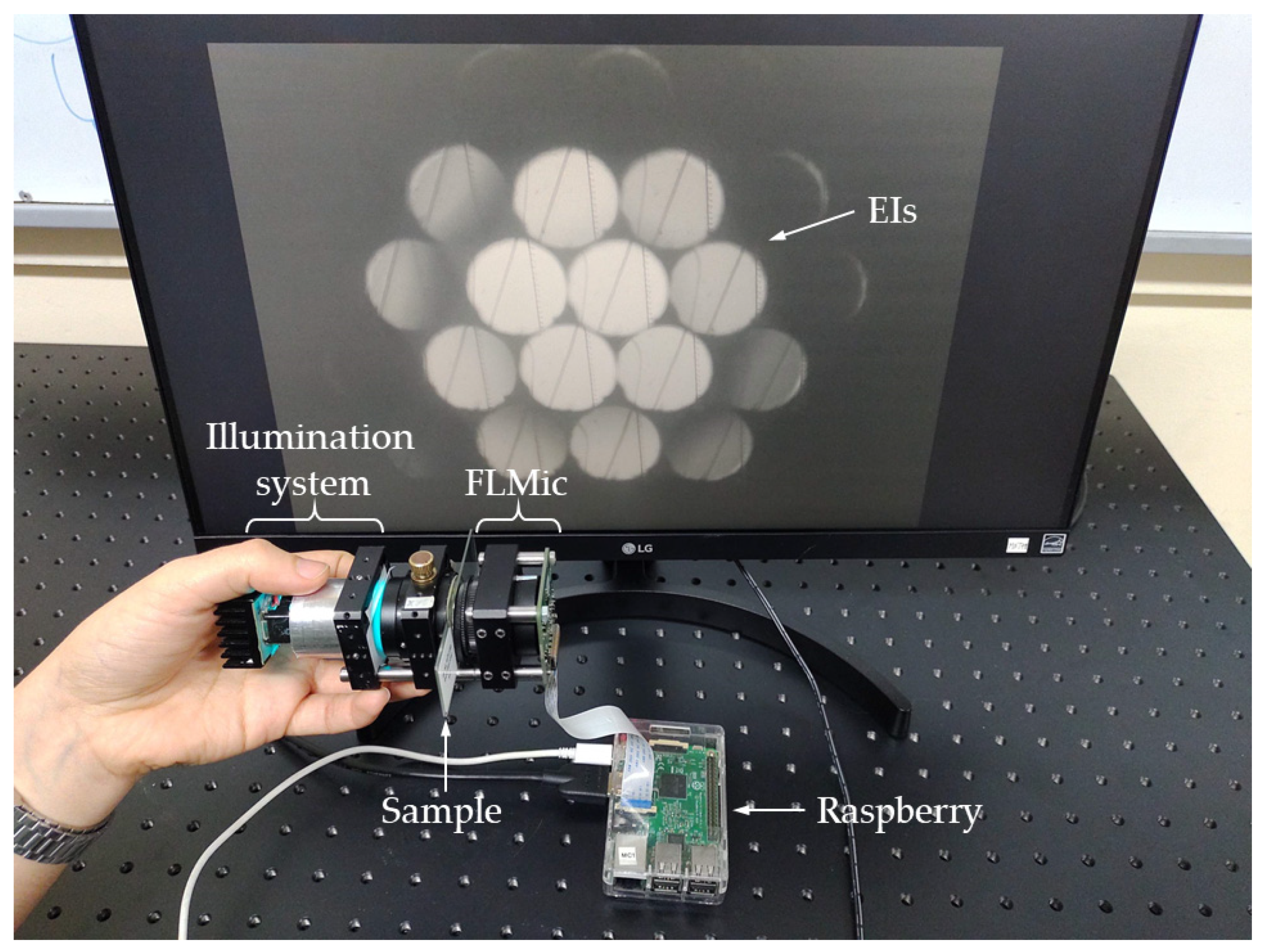
Figure 2, a photograph of the handheld and cost-effective FLMic is shown. The microscope was built with an M12 lens (
and
mm), manufactured by ArduCam
®. The chosen MLA has a focal length of
mm and pitch of
mm (model APH-Q-P1000-R3.63, manufactured by AMUS
®). As a digital sensor, an HQ Raspberry-Pi Camera with
square pixels of
μm, was selected. For illuminating the sample an off-the-shelf ultra-bright blue LED, with emission peak wavelength of 490 nm and a full width at half maximum (FWHM) of 40 nm, was used. The picture also includes the Raspberry-Pi utilized to control the digital camera and the illuminating LED.
To limit the FOV and avoid the overlapping between EIs a field stop of 1 mm in diameter was placed close to the sample. This stop was built by drilling a hole with the said size on an aluminum plate foil with 0.8 mm thickness. This maintains the cost effectiveness of the microscope. In the case of fluorescence, to collect the light emitted by the sample and to block the remaining light, we used recycled color plastic filters extracted from 3D anaglyph glasses. Again, this retains the system’s cost-effective design. Despite using low-cost elements, their performance is strong enough. The spectrum of the plastic filter was measured, obtaining a transmission peak at 610 nm and a FWHM of 60 nm. The weight of the microscope, below 400 g, can be further reduced by using specially designed and built (even by a 3D printer) hardware; however, in the prototype off-the-shelf elements were utilized. For this microscope, the expected theoretical values are , μm, mm, and μm.
To help the reader visualize the handheld nature of the designed microscope, in
Video S1 of Supplementary Materials a video recording of a microscopist operating the handheld FLMic is shown.
To show the effectiveness of the handheld and cost-effective FLMic, several experiments were completed. In the first experiment, the spatial lateral resolution of the microscope was studied by imaging a negative hi-res USAF 1951 test target.
Figure 3 shows, in the upper row from left-to-right: the complete set of the recorded EIs, the zoomed-in central EI, and a zoomed-in area including the elements from 1 to 4 of group 7. The set of recorded Els shows the 3,2 EIs (along the horizontal direction) for which the lightfield microscope was designed. From the zoomed-in area of the elements of group 7, an intensity profile along the green line is plotted. Here, the reader observes that the microscope can resolve with a contrast of 10% the element 1 of group 7, namely, it has a spatial resolution limit of
µm (or equivalently a cut-off frequency of 128.0 lp/mm). The lower row of
Figure 3 shows the same resolution study for the reconstructed image at the best focus plane. As it can be observed, both the reconstructed image and the EIs show the same resolution. From the same set of EIs images shown in
Figure 3, the
FOV of the microscope was measured to be 0.95 mm in diameter. Note that these two values are in very good accordance with the expected theoretical ones.
To measure the DOF, the USAF 1951 test target was imaged while it was axially displaced backwards and forwards. The DOF is the distance the test is displaced in both directions till the resolution is reduced by factor , i.e., in three elements with respect to the best focus plane. Taking this criterion, a DOF = 280 µm was measured for the handheld and cost-effective FLMic, which again matches very well with the expected value. The very good agreement between expected and experimental values validates the assumption that the impact of aberrations, due to the use of M12 lenses, is negligible.
Once the optical performance of the FLMic was evaluated, its feasibility to capture the three-dimensional information of thick samples was tested, both in bright-field and fluorescence imaging. As a bright-field sample, a honeybee wing was utilized. The captured EIs are shown in
Figure 4a. Using the seven non-vignetted EIs, nine refocused planes were computed by means of the S&S algorithm, which are presented in
Figure 4b. The axial step between the refocused images for this configuration is 12.5 µm. In
Video S2 of Supplementary Materials we show a movie in which the frames are refocused images.
The handheld FLMic microscope can be also applied to obtain images of fluorescent samples. For the next experiment, a sample of a knot of cotton fibers, dyed with Rhodamine 123, was utilized. The set of recorded EIs is shown in
Figure 5 panel (a). Instead of applying the classic S&S algorithm, the shift and multiply (S&M) algorithm was utilized to take advantage of its optical sectioning capability in the case of sparse fluorescent samples. In panel (b), several refocused images are presented. A 3D rendering, obtained by applying to these depth planes a maximum intensity projection (MIP) algorithm, was also created. The 3D rendering is composed of 46 refocused planes, so the rendered volume has a size of 950 × 950 µm
2 in the transverse axes and 575 µm in the axial one in the object space. In
Video S3 of Supplementary Materials, different views of the said rendering are shown. The voxel size of the rendering is 1.89 × 1.89 × 6.25 µm
3, where the larger side corresponds to the axial direction.
4. Conclusions
The design, implementation, and testing of the most portable, easy-to-build, robust, handheld, and cost-effective Fourier Lightfield Microscope (FLMic) to date, were presented. The design of the presented FLMic is an alteration of the original one with the removal of the relay lenses, the relocation of a cost-effective handmade field stop, and the replacement of the expensive infinity-corrected microscope objective (MO) by a surveillance M12 lens. This latter cost-effective lens, as utilized in the reverse direction of light gathering of its meant design, behaves as a competitive infinity-corrected MO with costing at least 100 times less than an equivalent regular commercial MO. In this system, the EIs are formed at transverse positions close to the optical axis, thus, the possible aberrations introduced by this non-scientific-grade lens are not relevant in this region, resulting in images of high optical quality. The design also accomplished the proper matching of the parameters of the MLA with the chosen digital camera to not jeopardize the optical performance of the complete FLMic. For the implementation of the proposed microscope, a M12 lens with 8 mm focal length was housed in a home-made cage that also allocates the MLA in contact with the lens. At the focal plane of the MLA an HQ Raspberry-Pi Camera was placed to record the elemental images. These images were processed via the regular refocusing algorithm to produce the refocused images at different depth planes. The proposed FLMic showed the optical performance dictated by the theory, similarly to that of a bulkier and much more expensive FLMic built based on expensive MO and relay lenses. The results showed that despite its at least 100 times lower price, optically-wise the proposed FLMic exhibits a competitive performance, while maintaining the real-time single shot 3D imaging capabilities. Therefore, the FLMic proposed here shows great promise as a handheld device for in-field 3D-imaging studies where a cost-effective device with competitive optical performance is the preferred choice.
Supplementary Materials
The following are available online at
https://www.mdpi.com/article/10.3390/s22041459/s1, Video S1: Video recording of a microscopist while operating the handheld FLMic, Video S2: Movie where frames are refocused images of a honeybee wing, Video S3: Different views of the 3D rendering of the knot of cotton-stained fibers.
Author Contributions
Conceptualization, L.G., J.C.B. and E.S.-O.; methodology, G.S. and J.G.-S.; software, L.G., E.S.-O. and H.Y.; validation, L.G., J.G.-S. and E.S.-O.; formal analysis, E.S.-O. and M.M.-C.; investigation, L.G. and J.C.B.; resources, J.C.B.; writing—original draft preparation, L.G.; writing—review and editing, E.S.-O. and J.G.-S.; visualization, H.Y.; supervision, J.G.-S. and M.M.-C.; project administration, M.M.-C. and G.S.; funding acquisition, M.M.-C. and G.S. All authors have read and agreed to the published version of the manuscript.
Funding
This research was funded by Grant RTI2018-099041-B-I00, which is cofounded by the Ministerio de Ciencia, Innovacion y Universidades (Spain) and by European Regional Development Fund; by Generalitat Valenciana (Spain) under Grant PROMETEO/2019/048; and by Universidad Nacional de Colombia Sede Medellin under Grant Hermes 50069.
Data Availability Statement
Conflicts of Interest
The authors declare no conflict of interest.
References
- Llavador, A.; Sola-Pikabea, J.; Saavedra, G.; Javidi, B.; Martínez-Corral, M. Resolution improvements in integral microscopy with Fourier plane recording. Opt. Express 2016, 24, 20792–20798. [Google Scholar] [CrossRef] [PubMed] [Green Version]
- Scrofani, G.; Sola-Pikabea, J.; Llavador, A.; Sanchez-Ortiga, E.; Barreiro, J.C.; Saavedra, G.; Garcia-Sucerquia, J.; Martinez-Corral, M. FIMic: Design for ultimate 3D-integral microscopy of in-vivo biological samples. Biomed. Opt. Express 2018, 9, 335–346. [Google Scholar] [CrossRef] [PubMed]
- Martinez-Corral, M.; Javidi, B. Fundamentals of 3D imaging and displays: A tutorial on integral imaging, light-field, and plenoptic systems. Adv. Opt. Photonics 2018, 10, 512–566. [Google Scholar] [CrossRef] [Green Version]
- Guo, C.; Liu, W.; Hua, X.; Li, H.; Jia, S. Fourier light-field microscopy. Opt. Express 2019, 27, 25573–25594. [Google Scholar] [CrossRef]
- Levoy, M.; Ng, R.; Adams, A.; Footer, M.; Horowitz, M. Light field microscopy. ACM Trans. Graph. 2006, 25, 924–934. [Google Scholar] [CrossRef]
- Levoy, M.; Zhang, Z.; McDowall, I. Recording and controlling the 4D light field in a microscope using microlens arrays. J. Microsc. 2009, 235, 144–162. [Google Scholar] [CrossRef] [Green Version]
- Broxton, M.; Grosenick, L.; Yang, S.; Cohen, N.; Andalman, A.; Deisseroth, K.; Levoy, M. Wave optics theory and 3-D deconvolution for the light field microscope. Opt. Express 2013, 21, 25418–25439. [Google Scholar] [CrossRef]
- Llavador, A.; Scrofani, G.; Saavedra, G.; Martinez-Corral, M. Large depth-of-field integral microscopy by use of a liquid lens. Sensors 2018, 18, 3383. [Google Scholar] [CrossRef] [Green Version]
- Wagner, N.; Norlin, N.; Gierten, J.; de Medeiros, G.; Balázs, B.; Wittbrodt, J.; Hufnagel, L.; Prevedel, R. Instantaneous isotropic volumetric imaging of fast biological processes. Nat. Methods 2019, 16, 497–500. [Google Scholar] [CrossRef]
- Stefanoiu, A.; Page, J.; Symvoulidis, P.; Westmeyer, G.G.; Lasser, T. Artifact-free deconvolution in light field microscopy. Opt. Express 2019, 27, 31644–31666. [Google Scholar] [CrossRef]
- Zhang, Y.; Lu, Z.; Wu, J.; Lin, X.; Jiang, D.; Cai, Y.; Xie, J.; Wang, Y.; Zhu, T.; Ji, X.; et al. Computational optical sectioning with an incoherent multiscale scattering model for light-field microscopy. Nat. Commun. 2021, 12, 6391. [Google Scholar] [CrossRef] [PubMed]
- Sanchez-Ortiga, E.; Scrofani, G.; Saavedra, G.; Martinez-Corral, M. Optical sectioning microscopy through single-shot lightfield protocol. IEEE Access 2020, 8, 14944–14952. [Google Scholar] [CrossRef]
- Liu, F.L.; Kuo, G.; Antipa, N.; Yanny, K.; Waller, L. Fourier diffuserScope: Single-shot 3D Fourier light field microscopy with a diffuser. Opt. Express 2020, 28, 28969–28986. [Google Scholar]
- Stefanoiu, A.; Scrofani, G.; Saavedra, G.; Martinez-Corral, M.; Lasser, T. What about computational super-resolution in fluorescence Fourier light field microscopy? Opt. Express 2020, 28, 16554–16568. [Google Scholar] [CrossRef] [PubMed]
- Hua, X.; Liu, W.; Jia, S. High-resolution Fourier light-field microscopy for volumetric multi-color live-cell imaging. Optica 2021, 8, 614–620. [Google Scholar] [CrossRef] [PubMed]
- Cong, L.; Wang, Z.; Chai, Y.; Hang, W.; Shang, C.; Yang, W.; Bai, L.; Du, J.; Wang, K.; Wen, Q. Rapid whole brain imaging of neural activity in freely behaving larval zebrafish (Danio rerio). eLife 2017, 6, e28158. [Google Scholar] [CrossRef] [PubMed]
- Yoon, Y.G.; Wang, Z.; Pak, N.; Park, D.; Dai, P.; Kang, J.S.; Suk, H.J.; Symvoulidis, P.; Guner-Ataman, B.; Wang, K.; et al. Sparse decomposition light-field microscopy for high speed imaging of neuronal activity. Optica 2020, 7, 1457–1468. [Google Scholar] [CrossRef]
- Javidi, B.; Carnicer, A.; Arai, J.; Fujii, T.; Hua, H.; Liao, H.; Martínez-Corral, M.; Pla, F.; Stern, A.; Waller, L.; et al. Roadmap on 3D integral imaging: Sensing, processing, and display. Opt. Express 2020, 28, 32266–32293. [Google Scholar] [CrossRef]
- Sims, R.R.; Rehman, S.A.; Lenz, M.O.; Benaissa, S.I.; Bruggeman, E.; Clark, A.; Sanders, E.W.; Ponjavic, A.; Muresan, L.; Lee, S.F.; et al. Single molecule light field microscopy. Optica 2020, 7, 1065–1072. [Google Scholar] [CrossRef]
- Cui, Q.; Park, J.; Ma, Y.; Gao, L. Snapshot hyperspectral light field tomography. Optica 2021, 8, 1552–1558. [Google Scholar] [CrossRef]
- Wang, Z.; Zhu, L.; Zhang, H.; Li, G.; Yi, C.; Yang, Y.; Ding, Y.; Zhen, M.; Gao, S.; Hsiai, T.K.; et al. Real-time volumetric reconstruction of biological dynamics with light-field microscopy and deep learning. Nat. Methods 2021, 18, 551–556. [Google Scholar] [CrossRef] [PubMed]
- Incardona, N.; Tolosa, A.; Scrofani, G.; Martinez-Corral, M.; Saavedra, G. The lightfield microscope eyepiece. Sensors 2021, 21, 6619. [Google Scholar] [CrossRef] [PubMed]
- Scrofani, G.; Saavedra, G.; Martínez-Corral, M.; Sánchez-Ortiga, E. Three-dimensional real-time darkfield imaging through Fourier lightfield microscopy. Opt. Express 2020, 28, 30513–30519. [Google Scholar] [CrossRef] [PubMed]
- Prevedel, R.; Yoon, Y.G.; Hoffmann, M.; Pak, N.; Wetzstein, G.; Kato, S.; Schrödel, T.; Raskar, R.; Zimmer, M.; Boyden, E.S. Simultaneous whole-animal 3D imaging of neuronal activity using light-field microscopy. Nat. Methods 2014, 11, 727–730. [Google Scholar] [CrossRef]
- Ghosh, K.K.; Burns, L.D.; Cocker, E.D.; Nimmerjahn, A.; Ziv, Y.; el Gamal, A.; Schnitzer, M.J. Miniaturized integration of a fluorescence microscope. Nat. Methods 2011, 8, 871. [Google Scholar] [CrossRef] [Green Version]
- Switz, N.A.; D’Ambrosio, M.V.; Fletcher, D.A. Low-Cost Mobile Phone Microscopy with a Reversed Mobile Phone Camera Lens. PLoS ONE 2014, 9, e95330. [Google Scholar] [CrossRef] [PubMed] [Green Version]
- Lu, Q.; Liu, G.; Xiao, C.; Hu, C.; Zhang, S.; Xu, R.X.; Chu, K.; Xu, Q.; Smith, Z.J. A modular, open-source, slide-scanning microscope for diagnostic applications in resource-constrained settings. PLoS ONE 2018, 13, e0194063. [Google Scholar] [CrossRef] [PubMed]
- Daniel, A.; Hoogland, T.M. Circuit investigations with open-source miniaturized microscopes: Past, present and future. Front. Cell. Neurosci. 2019, 13, 141. [Google Scholar]
- Yanny, K.; Antipa, N.; Liberti, W.; Dehaeck, S.; Monakhova, K.; Liu, F.; Shen, K.; Ng, R.; Waller, L. Miniscope3D: Optimized single-shot miniature 3D fluorescence microscopy. Light Sci. Appl. 2020, 9, 171. [Google Scholar] [CrossRef]
- Collins, J.T.; Knapper, J.; Stirling, J.; Mduda, J.; Mkindi, C.; Mayagaya, V.; Mwakajinga, G.A.; Nyakyi, P.T.; Sanga, V.L.; Carbery, D.; et al. Robotic microscopy for everyone: The OpenFlexure microscope. Biomed. Opt. Express 2020, 11, 2447–2460. [Google Scholar] [CrossRef]
- The UCLA Miniscope Project. Available online: http://miniscope.org (accessed on 11 February 2022).
- These M12 Lenses Can Be Purchased to Different Suppliers, Like for Example, Lensation GmbH, KUBII, Arducam. Available online: www.lensation.de; www.kubii.es; www.arducam.com (accessed on 11 February 2022).
| Publisher’s Note: MDPI stays neutral with regard to jurisdictional claims in published maps and institutional affiliations. |
© 2022 by the authors. Licensee MDPI, Basel, Switzerland. This article is an open access article distributed under the terms and conditions of the Creative Commons Attribution (CC BY) license (https://creativecommons.org/licenses/by/4.0/).


 ,
, 