1. Introduction
DC in power grids is created due to induction from geomagnetic variations, DC power transmission, high-power electronic devices, and newly also by transformerless power inverters installed in solar power stations [
1]. These currents, ranging in extreme cases up to hundreds of amperes, seriously affect the energy measurement and create a challenge in maintaining the DC-bias currents [
2] at a certain level recommended by the grid codes [
3]. This creates demand for the mixed AC+DC measurement, such as the DC-bias currents measurement [
3] and AC measurement mixed with DC [
4,
5].
The standard CT used for the calibration of AC+DC measurement devices needs to have high AC and DC measurement accuracy under the condition of AC mixed with DC. The calibration of these AC+DC measurement devices require the input of AC mixed with DC. Due to the DC component, the accuracy of the standard CT based on the principle of electromagnetic induction will decline greatly and does not meet the requirements.
High-precision standard resistance is an ideal gauge of AC+DC, which is used as the calibration standard of anti-DC CT in Literature [
6]. However, the high-precision standard resistance will consume power and heat up as the current increases.
Most of the reported high precision AC and DC measurement schemes are based on the magnetic modulation method. A precision DC/AC transformer is combined with a magnetic-modulation DC comparator and self-balancing AC comparator [
7], which can measure AC and DC. The transformer consists of four iron cores and four windings. The electronic circuit includes an excitation oscillation circuit, peak detection circuit, amplifier circuit, and power amplification circuit. The errors at no DC component in the primary current are less than 20 ppm at currents between 1% and 100% of rated, and the errors, measured at DC between 10% and 100% of rated, are less than 100 ppm. There is no measurement data at AC mixed with DC. Meanwhile, the double core magnetic modulator has a false balance point, making its zero error larger.
Fluxgate magnetic modulation technology has the advantages of high resolution, wide measurement range, and high reliability. In the literature [
8], a high-precision AC/DC proportional standard device based on the fluxgate and zero-flux principle was proposed. Two or four differential fluxgate sensors are symmetrically placed on the iron core to detect the residual magnetic potential caused by the imbalance between the primary and secondary currents. The accuracy of the prototype with a transformation ratio of 500:1 reaches level 0.01 at the power frequency AC 1–120% rated current and DC 1–120% rated current. Each fluxgate sensor requires external excitation. Additionally, to achieve the accuracy of level 0.01, the scheme requires four groups of fluxgate sensors to be symmetrically installed in the iron core to form a current sensor, which has high requirements for the processing technology of the iron core.
The magnetic modulator current sensing technology needs an external excitation source and a complex demodulation circuit. Meanwhile, the self-excited oscillation fluxgate sensor does not require an external excitation source, and its structure is simple. The operating principle of the open-loop self-oscillating fluxgate current sensor based on either the average current detection method [
9,
10] or the duty cycle method [
11] has been studied. Compared with traditional fluxgate technology, the significant advantages of these sensors are their relatively simple modulation, demodulation circuits, and low cost.
However, due to the lower use of a magnetic core to compensate the modulation ripple induced in the primary and secondary windings due to the transformer effect, the obtained accuracy is only about 0.5% in the full scale of ±20 A [
12,
13].
A transducer combined with an improved self-oscillating fluxgate sensor with a magnetic integrator in a common feedback loop can measure DC up to ±600 A with a relative accuracy of 1.3 ppm in the full scale [
14]. An iron core coil is added to the self-excited oscillation fluxgate sensor structure to weaken the conduction ripple in the iron core. The iron core coil and the self-excited oscillation fluxgate form a DC measurement channel. The third iron core detects the residual AC ripple in the iron core to further weaken the induced ripple in the iron core and form an AC measurement channel. In this paper, the researchers did not measure AC.
The main goal of this paper is to develop a standard current transducer for the calibration of AC+DC sensors with a simpler structure and sufficient accuracy. In this paper, a simpler AC+DC current transducer is proposed, which is composed of two iron cores and three windings. An iron core and two windings are added onto the single-iron-core double-winding structure of the traditional self-oscillating fluxgate. The added iron core and one of the windings are used to suppress the ripple in the iron cores. By matching core parameters and external circuit parameters, the ripple is suppressed to the greatest extent. In addition, through the LPF (low pass filter) and HPF (high pass filter) design in the electronic circuit, the self-excited oscillation fluxgate can measure AC and DC. The additional winding feeds back AC and DC to make the sensor cores work in a zero-flux state. In this way, the sensor only needs two iron cores and three windings to realize the high-precision simultaneous measurement of AC and DC.
The structure of this paper is as follows: the relevant existing works of AC/DC sensor, and fluxgate current sensor are reviewed in
Section 1. Then, we introduce the single-core self-oscillating fluxgate current sensor principle in
Section 2. In
Section 3, the scheme for the AC+DC transducer is proposed in detail. In
Section 4, the development of the AC+DC transducer is presented. We test the transducer to verify the accuracy and effectiveness of the scheme in
Section 5. Finally, we summarize our work in
Section 6.
2. Structure of Self-Oscillating Fluxgate Current Sensor
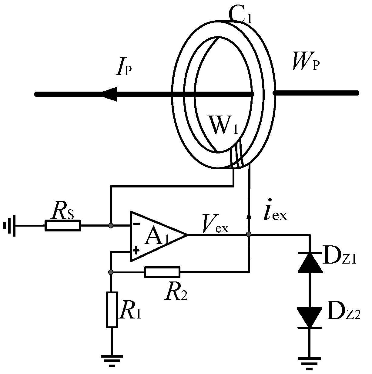
A schematic diagram of the open-loop self-oscillating fluxgate current sensor is shown in
Figure 1. The operating principle of this circuit can be found in [
9,
10,
11]. The excitation winding
and the nonlinear core
with high permeability and low magnetic saturation strength are equivalent to the nonlinear inductance L. The equivalent inductor L, the comparator
, the voltage dividing resistors
and
, and the sampling resistance
constitute a self-oscillating circuit.
When the self-oscillating fluxgate sensor operates, the excitation voltage
is a square wave signal with positive and negative symmetry. The iron core
is in a state of alternating positive and negative saturation. Through piecewise linearization modeling on the excitation curve, it can be obtained that the period T of
meets
where
is the number of turns of the excitation winding
.
is the magnetic saturation strength of the core
.
S is the cross-sectional area of core
.
is the peak value of
. Therefore, the excitation frequency of core
can be calculated from the Formula (1).
According to the average current model [
10], when the primary current is DC, during self-oscillating the average value
of excitation current
meets
It can be seen from Formula (2) that the average excitation current is proportional to the primary current . Then the voltage generated by the exciting current on the sampling resistance can map the primary current .
3. Principle of Zero-Flux Self-Oscillating AC+DC Transducer
3.1. Composition of AC+DC Transducer System
In this paper, a zero-flux AC+DC sensing scheme based on the structure of self-oscillating fluxgate is proposed. See
Figure 2 for its system composition. The self-oscillating flux gate serves as the zero-flux detector to detect AC+DC unbalanced magnetic potential, and the AC+DC feedback current flows through the feedback winding
to make the cores in a zero-flux state. The ring core
, the exciting winding
, and the inverted amplifier
reduces the electromagnetic induction noise, and the measuring accuracy is improved. The AC+DC sensing system is only of double-core three-winding configuration. Therefore, the iron core structure of the transducer is simplified and the overall cost is reduced.
In
Figure 2, the sensing system includes the current detection module, signal processing module, error control module, and feedback module. In the current detection module, the ring iron cores
and
are nonlinear ferromagnetic materials of the same geometrical dimensions and magnetic parameters with high magnetic permeability, low coercive force, and high magnetic saturation induction strength. The excitation windings
and
with the number of turns
and
are evenly wound on the core
and
respectively. The comparator
, the winding
and external resistances
,
, and
form a self-excited oscillation fluxgate. The square excitation voltage
is output from
. The amplifier
is an opposite single-proportional amplifier. The exciting currents of cores
and
are of the same amplitude and opposite phase, and, therefore, the cores
and
operates in an opposite exciting state.
When the primary current flowing in the primary winding
is
. The output voltage
and
on the resistor
and
is processed by the signal processing module, PI error module and PA circuit to generate feedback current in the feedback winding
. Finally, when the two iron cores are in zero flux state, the feedback current
is proportional to the primary current. The magnetic potential balance equation for the toroidal cores
and
satisfies
It follows from Formula (3) that when the sensing system reaches balance, the feedback current
is proportional to the primary current
, and the transformation ratio is
. The voltage signal
output from the resistor
and primary current
shall satisfy the following requirements.
The sensitivity
can be derived from Equation (4):
Equation (5) shows that the sensitivity of the AC+DC transducer is proportional to the resistance of and inversely proportional to the number of turns of feedback winding.
3.2. Improvement of Transducer Performance by Zero-Flux
Due to the transformer effect, the square wave excitation flux of will induce the ripple current in two windings and , which affects the accuracy of the transducer. To suppress the noise generated by the electromagnetic induction, the ring iron core , excitation winding , and the inverse amplifier are used to improve the performance of the transducer.
If there is no core
with anti-excitation and the transducer is of a single core structure, then the magnetic potential equation of the core
is
From (6), it is known that excitation current is still the main cause for the error of this transducer similar to traditional CTs.
Add a core
with the same magnetic parameters and geometrical dimensions as
and the excitation voltage
of core
is inverted and directly used as the excitation voltage of core
. Here, the magnetic potential equations of the cores
and
are, respectively:
Add (7) and (8) together, i.e., the cores
and
are considered a whole, for the following:
According to (9), the double-core self-oscillating fluxgate transducer can operate as a zero-flux state, thereby eliminating the impact on the measurement result of the single-core structure due to the electromagnetic induction, and achieving higher current detection accuracy of the AC+DC transducer.
3.3. Improvement of Transducer Performance by Demodulation Circuit Optimization
When the transducer measures the AC mixed with DC, the induced current on the excitation winding makes the excitation process of the iron core more complex and the nonlinear characteristics more obvious. A large number of high-frequency harmonics are generated in the excitation current. In this scheme, the high-frequency harmonic signals are effectively filtered out by the optimized demodulation circuit, and thus the measurement accuracy of the AC+DC transducer is improved.
When the primary current is the AC mixed with DC, the ring core
is in the forward excitation state, and then the output voltage
on the sampling resistor
consists of two parts:
and
.
is a low-frequency signal, including a DC component
proportional to the primary DC and an AC component
proportional to the primary power frequency current. Meanwhile, a high harmonic current in the excitation signal also causes a high-frequency component
. Since the magnetizing state of the toroidal core
is precisely opposite to that of the core
, The output signal
on the sampling resistance
consists of
and
which are inverted with
and
, respectively. High-pass filtering is performed on
and only the high-frequency component
is retained. Thanks to the symmetry of the sensor structure and parameters, in theory, the two signals
and
have equal amplitudes and inverse phases. Then add
and
to get
Equation (10) is an ideal output expression. However, the actual circuit cannot ensure consistency between , , and the additional circuit. It is impossible to eliminate the high-frequency component. It is necessary to filter the high-frequency component of the signal further by low-pass filtering, to reduce the influence of electromagnetic induction.
4. Development of AC+DC Transducer Prototype
4.1. Parameters of Cores
According to the requirements of a zero-flux self-oscillating flux transducer for the ferromagnetic parameters, the geometric and magnetic parameters of the cores
and
are summarized in
Table 1.
4.2. Circuit Parameter
(1) Comparator
The performance parameters, such as power supply, load capacity, noise, and bandwidth of comparator are factors that affect the measurement accuracy of the transducer. A high-precision operation amplifier OP27G with a dual power supply is used. The supply voltage is limited to ±15 V, and the output current can reach 40 mA under 100 ohm load. Meanwhile, OP27G is characterized by a wide frequency bandwidth and low noise. The input offset current is less than 35 nA, and the unity gain-bandwidth product is 8 MHz. The phase inverter and comparator is of the same type.
(2) Excitation Frequency
From Formula (1), the relationship between the excitation frequency
, excitation voltage, and core parameters is as follows:
The excitation frequency should not be too high, since the vortex loss of magnetic material is proportional to the square of the excitation frequency . As the excitation frequency increases, the vortex loss in the core will increase, and the overall power consumption of the AC+DC transducer will increase. From (11), when the excitation voltage is constant, the higher the excitation frequency , the lower the number of turns of the excitation winding, and the higher the saturation current threshold of the core. Then, the core is difficult to enter the saturation area, which reduces the linearity of the transducer.
While the excitation frequency
is too low, the number of turns
of the excitation winding is too large, and the transducer’s sensitivity will be decreased. Therefore, it is necessary to focus on the linearity and sensitivity in the design of parameters. According to the condition of the excitation frequency limit
> 2
(
is the frequency of primary current), when the detection bandwidth of AC and DC sensor is 0–50 Hz, the excitation frequency of the self-oscillating fluxgate transducer shall be designed to be higher than 100 Hz. In the design, the number of turns
of the excitation windings
is 175, and the excitation square wave voltage is ±5 V. From (11) and the core parameters in
Table 1, the excitation frequency of the AC+DC transducer is calculated to be 129 Hz, meeting the requirements for bandwidth detection.
(3) LPF and HPF
The function of HPF is to retain the high-frequency signal in excitation winding , its cut-off frequency is set to 59 Hz. The output signal of the HPF is added to the output signal of the excitation winding to weaken the mutual inductance effect. To further filter out the high-frequency signal in the synthetic signal, a low-pass filter retaining only DC and power frequency signals is set, and its cut-off frequency is also set to 59 Hz. Therefore, the high-frequency ripple signal generated by the mutual inductance effect is greatly attenuated in the output signal .
(4) Feedback circuit
To reduce the output ripple of the power amplifier circuit, a traditional AB-type power amplification circuit is applied in this design. The power devices
are TIP 110 and TIP 117, which have the same parameters, and are high-power Darlington tubes, with the maximum AC output as high as 2 A. The power amplifier circuit is shown in
Figure 3.
4.3. Physical Transducer
Figure 4 shows the AC+DC transducer prototype based on the above principles and methods. Here are the main parameters of the given prototype. The transformation ratio: 1000:1; Rated AC: 500 A; Rated DC: 250 A; Sensitivity: 5 mV/A; and Bandwidth: 0–50 Hz.
5. Performance Test of AC+DC Transducer Prototype
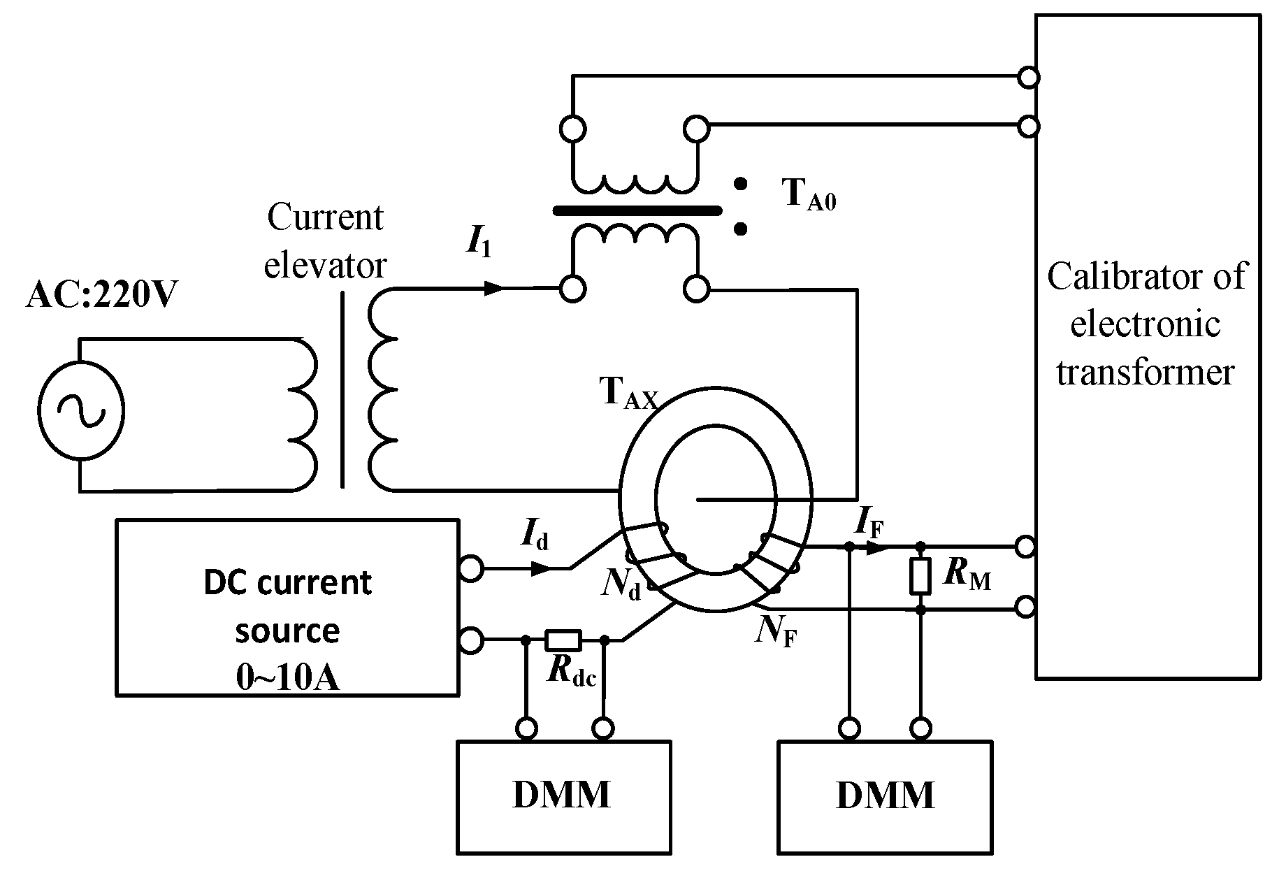
The AC+DC measuring performance of the prototype is tested based on the proportional DC superposition method. See
Figure 5 for the test principle and
Figure 6 for the wiring diagram. The test equipment and parameters are as follows.
- (1)
Current elevator. Capacity: 20 kVA; Maximum output current: 3 kA;
- (2)
Standard current transformer Model: HL 28-5; Rated burden: 10 VA; Rated primary current: 500 A; Rated secondary current: 5 A; Accuracy class: 0.05;
- (3)
DC source. Model: YJ-10 A; Output current: 0;
- (4)
DC standard resistance Resistance: 0.1 Ω; Capacity: 10 A at 20 °C; Temperature drift: 10 ppm; Accuracy class: 0.01;
- (5)
Calibration instrument of electronic transformers. Model: XL-809; Input range: 0–8 V; Accuracy class: 0.05;
- (6)
Six and a half digital multimeter DDM. Model: KEITHLEY 2000; DC voltage accuracy: 0.002%.
In
Figure 5,
is the tested high-precision AC+DC transducer prototype. AC output by the elevator passes through
and standard current transformer
. DC is produced by the DC source and loaded on
through equal ampere-turns. The output signal of
is obtained from the sampling resistor
and input to the electronic transformer calibration instrument and DMM1 at the same time. The standard current transformer
converts the primary AC into low voltage and transmits it to the electronic transformer calibration instrument. The electronic transformer calibrator gives the AC verification results through synchronous sampling and calculation. The DC standard resistance transforms the primary DC into low voltage and transmits it to DMM2. The verification results of DC are calculated through the synchronous readings of the two DMMs. The ratio error and phase error are, respectively, calculated according to the standard definitions of the transformer, respectively, expressed in percentage and minute.
By the Proportional DC Superposition Method testing scheme, AC measuring performance, DC measuring performance, and AC/DC mixed current measuring performance of prototype are explored.
5.1. AC measuring Performance Testing
According to the Verification Code for Current Transformer for Measurement, the DC circuit was disconnected during testing, and the ratio error and phase error of the AC+DC transducer prototype with forward and backward strokes of 5%, 20%, 100%, and 120% of the rated current were, respectively, tested. The test results are shown in
Figure 7a,b.
The red curve in
Figure 7 is the limit curve of ratio error and phase error of the 0.05 class AC CT. It can be seen that the measured results of the prototype are within the error limits of the 0.05 class CT.
5.2. DC Measuring Performance Testing
Referring to the Verification Code for Current Transformer for Measurement for DC characteristics testing, the equal ampere-turn method is used to extend the DC measuring range and the primary AC circuit is disconnected during testing. The test results within the range of 0–120% rated DC are shown in
Figure 8.
The horizontal coordinate of
Figure 8 is the equivalent primary DC and the vertical coordinate is the scale error. The red curve is the limit curve of the 0.05 class DC CT proportional error. It can be seen that the DC scale error of the transducer is within the error limit of 0.05 class CT in the DC range of 0–300 A.
5.3. AC+DC Measurement Performance Testing
Along with the Proportion DC Superposition method and the equal ampere-turn method, AC and DC are input simultaneously to explore the measurement performance when AC and DC are applied simultaneously, including the effects of DC component on AC measurement and AC component on DC measurement.
5.3.1. Influence of DC Component on AC Measurement
The ratio error and phase error of the AC+DC transducer prototype within the range of 0–600 A are tested when the DC component is fixed at 20 A and 50 A respectively. The test results are shown in
Figure 9.
The red curve in
Figure 9 is the limit curve of ratio error and phase error of the 0.05-class AC CT. It can be seen from
Figure 9 that with a fixed DC of 20 A and 50 A, the ratio error and phase error of the AC+DC transducer does not change significantly, and still satisfies the AC error limit of the 0.05-class. It indicates that the DC component has no significant effect on the measurement of AC.
5.3.2. Influence of AC on DC Measurement
The DC scale error within the range of 0–300 A is tested when the AC is fixed at 25 A and 250 A, respectively. The test results are shown in
Figure 10.
As shown in
Figure 10, the red curve is the limit curve of the 0.05 class DC CT. It can be seen from
Figure 10 that the DC measurement results still satisfy the 0.05 class DC error limit for an AC component of 25 A and 250 A. The magnitude of AC has no noticeable effect on the DC measurement error.
6. Conclusions
The measurement accuracy of the standard CT used for AC CT calibration cannot meet the calibration when AC and DC currents are mixed. It requires a high accuracy standard current transducer that can measure AC and DC simultaneously. An AC+DC transducer based on zero-flux self-oscillating fluxgate is proposed in this paper. Some parameters of the transducer are: Rated AC: 500 A; Rated DC: 250 A; Bandwidth: 0–50 Hz. The ratio error and phase error of the transducer prototype are within the error limit of class 0.05 CT at the range of 5–120% of the rated current When only DC or AC. The errors of the transducer are also tested at AC mixed with DC and DC mixed with AC. The ratio error and phase error of the prototype at the AC range of 0–600 A are within the error limit of class 0.05 CT when the DC component is fixed at 20 A and 50 A, respectively. The DC scale error at the range of 0–300 A is within the error limit of class 0.05 CT when the AC is fixed at 25 A and 250 A, respectively. The transducer can calibrate AC CTs, DC CTs, and anti-DC CTs with an accuracy level not high than 0.2.
The AC+DC transducer proposed in this paper has a simpler structure and only needs double cores and three windings. However, at present, the sensor has high accuracy only under the power frequency AC mixed with DC; that is, its bandwidth is limited. The research team is trying to expand the bandwidth of the sensor by changing the excitation frequency of the self-excited oscillation circuit and the matching of circuit parameters to make it more widely used, such as the calibration under half-wave current.


