1. Introduction
The issue of laser ranging measurements of artificial Earth satellites dates back to 1964. With the launch of the Beacon Explorer (Beacon-B) satellite by the National Aeronautics and Space Administration (NASA), the first laser measurement of the distance between a ground station and an orbital object was carried out [
1]. Over the years with the development of laser technology, optics, control and executive systems, the accuracy of laser range measurements on the ground station—satellite path has increased many times and currently ranges from 1 cm to 2 cm. The fact of the progress made in building time and frequency references is also not without significance (hydrogen masers, cesium fountains) [
2], thanks to which it is possible to accurately and precisely locate a specific observation in the time domain. The greatest advantage of the laser technique is the direct and absolute measurement of the distance between the ground station and the orbital object (satellite, rocket bodies, space debris). These measurements make a huge contribution to research on the implementation and definition of the terrestrial reference system, the International Terrestrial Reference Frame (ITRF), pole movement, the coordinates of the geocenter of the Earth’s gravitational field, the coordinate and velocity changes of the position of ground SLR stations [
3,
4], and determining the position of objects orbiting Earth with centimeter accuracy. However, due to the continual migration of continents, this is a complex and multi-stage process (the position of the ground station changes). The key solution to the above is the use of passive geodynamic satellites such as LAGEOS [
5] (orbit altitude ∼ 6000 km) or ETALON [
6] (orbit altitude ∼ 19,000 km), whose location at the Medium Earth Orbit (MEO) ensures the stability of their orbit over time (no influence of atmospheric effects). This constancy enables the determination of the current position of a given SLR station and, consequently, means it is suitable for measurements of other orbital objects. The continuous and almost simultaneous carrying out of this process by all laser ground stations enables the determination of their position, as well as the determination of geodynamic satellites’ orbits. In classical terms, laser range measurements are carried out for orbits from the Low Earth Orbit (LEO) region (altitude from 200 km to 2000 km) to Geostationary Orbit (GEO).
Currently, due to the dynamic exploration of orbits (LEO to GEO) associated with the launch of new satellites for the needs of industry, science, and defense, there is a need for increased monitoring of the traffic of orbital objects and the deorbiting process of used components such as rocket bodies, satellite fragments, as well as entire satellites [
7]. From the point of view of the laser measurements performed by ground stations, orbital objects can be classified as cooperative and uncooperative. Cooperative objects, mainly satellites, are equipped with special systems of cubic prisms (retroreflectors) mounted on the outer casing, whose task is the low-loss reflection of the laser beam emitted from the ground station. Uncooperative objects are therefore all other orbital objects that are not equipped with retroreflectors (satellites, rocket bodies, space debris). This fact forces the use of high-energy laser measurement pulses, which increase the probability of a photon event in the form of light scattering from the object and its subsequent detection. Laser ranging measurements of cooperative satellites in the region from 350 km to 40,000 km are currently not a challenge in terms of tracking, but ranging measurements of objects with uncertain orbits or subject to deorbiting (altitude from 100 km to 200 km) require the use of new solutions in the fields of mechanics, drives, and control algorithms, hence the need to develop new control algorithms and the multiplication of measurement techniques in order to maximize information about the object during the pass over the ground station [
8,
9,
10]. The laser technique, whose task is to accurately and precisely measure the range between the SLR ground station and orbital object in the time domain, also allows determining the dynamics of an object (spin) using a picosecond laser source [
11,
12]. Passive optical acquisition allows the use of a telescope and digital cameras (CCD, CMOS, sCMOS) to determine the orbital parameters of an object [
13] and can also be used to obtain additional information using techniques such as light curves [
14], which show the momentary variability of the brightness of objects, or further attempts to characterize the mission. The combination of these techniques makes it possible to obtain more data during a single pass of an object over a ground station.
The positional uncertainty of radar ephemerides in the form of Two-Line Elements set files (TLEs), in terms of their initial accuracy resulting from the inaccuracy of the radar survey technique, often cause problems in the tracking process behind an orbital object. Particular mention should be made of deorbiting events (orbit perigee 200 km), the trajectory of which is constantly disturbed, implying a rapid obsolescence of ephemeris information, hindering the process of effective tracking of such objects. SLR stations perform point measurements, so the quality of the reflection of the theoretical ephemeris position of the orbital object above the station in relation to the real trajectory is important. Classically, the Field of View (FoV) of the transceiver telescope together with the photon detector enables tracking of an orbital object from the LEO region with an offset to the theoretical trajectory usually no greater than 50 ms (TimeBias). For offsets greater than the limit value of the FoV of the telescope, measurements are difficult to perform (the object is not visible in the field of view of the receiving telescope). In the case of regular tracking of cooperative satellites under the International Laser Ranging Service (mainly altimetric satellites and GNSS), it is possible to obtain current information about the appropriate correction to the object’s position (TimeBias). Thus, taking into account the value of the given offset, it is possible to correct the tracking ephemeris. In the case of tracking of uncooperative objects, the information about the theoretical trajectory, which is based on the TLE ephemeris, it is impossible to determine the offset of the position of the orbital object before performing the tracking process. This situation is particularly important in the case of re-entry events (object deorbiting), where the difference between the theoretical position of the object and the real trajectory is even a few seconds. It should also be mentioned that the positional accuracy of the TLE ephemeris over time is lost. For the LEO region, the TLE ephemeris loses its operational accuracy for the classic SLR station after 24 h. Due to the above, there is a need to make ongoing corrections of the tracking process behind the orbital object.
2. Satellite Laser Ranging Process
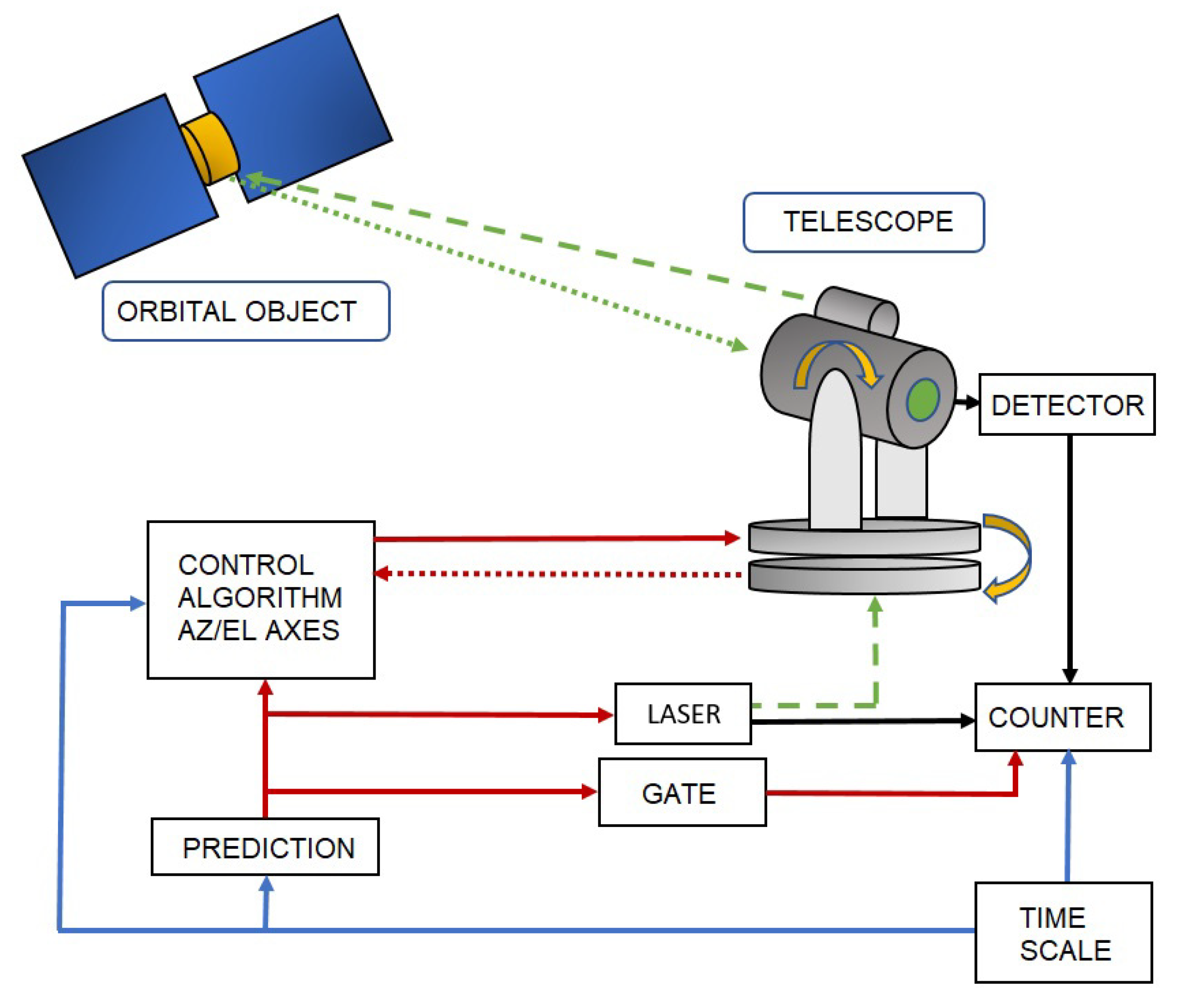
The laser ranging measurements of an orbital object are carried out by using a pulsed laser source, as a measuring beam emitter with the specified beam divergence
, and a photon detector placed in the main focus of the receiving telescope operating mostly in the
configuration (
Figure 1). The detector is responsible for the acquisition of photons (
) scattered by the orbital object (
) from the previously emitted laser beam. The laser range measurement is based on the emission of a laser pulse of known length (
ps,
ns) at the
moment of time, in the direction of the orbital object where some of the photons are scattered from the object’s surface. The
moment of time, when the returning scattered photons are acquired by the photon detector, ends the measuring procedure. Therefore, the range measurement procedure consists of measuring the time interval
, which is necessary for the light pulse to travel the station–object–station distance (
). The task of the telescope’s movement control is to transform the ephemeris information
about the position of the tracked object
into the follow-up movement of the telescope’s mount. Therefore, the position of the spatial point
,
,
should be transformed into the azimuth and elevation angles (
) for a given location of the SLR station. Due to the non-stationary nature of the process, the task is dynamic. Thus, the accuracy of the tracking process (mapping the motion of the telescope’s mount) directly depends on the control process and the accuracy of the drive system and intermediate mechanics [
15].
2.1. Tracking Process
Taking into account the dynamics of the changes in the angular position () of the orbital object in relation to the ground station position in the time domain (mainly for the LEO region) and the required high accuracy of the tracking process (; due to laser beam divergence) with respect to the uncertain of the theoretical position of the object, the task of the movement control should be carried out as continuously as possible (close to linear mapping). Therefore, the real object trajectory should be reflected by the iterative operation of the control algorithm, the result of which is projected onto the telescope follow-up movement. The iterative nature of the algorithm in predicting the successive points of the trajectory determines the computational time necessary to minimize the tracking error. In practice, it is assumed that the iteration interval should not be greater than 100 ms (mainly due to the high dynamics of position changes for objects from the LEO region). The tracking task is performed in two steps. In the first step, the time interval should be estimated, in which the position of the object (in relation to the station) will enable its observation. Specifying the beginning of the observation time (), the position of the object (, , ⇒/), and the telescope angles (/), the telescope is positioned relative to the beginning of the observation. This part of the procedure is not sensitive to the tracking process flow. The second stage starts at the time , when the algorithm starts the tracking procedure.
The procedure is based on the implementation of a software control loop, which consists of the following activities:
Importing the telescope’s axes encoder values: , in the moment of time;
Prediction of the theoretical position of the object based on the ephemeris: , , ⇒/, in the moment of time;
Determining the difference in the form of a correction (, );
Setting new motion parameters for the hardware layer ().
In contrast to the control loop implemented directly at the hardware layer, this approach allows flexibility in changing the motion parameters, although it is costly with additional software calculations outside the servomotor driver. There are a few approaches that determine the control method. The management software may provide with some advance (
) the drive controller information only about the new positions
,
,
(
/
) for a certain time
(the controller must be equipped with a local RT clock). Then, the hardware layer, in the form of the NC servo controller, makes appropriate calculations/corrections (e.g., position, velocity, acceleration) so that the controlled axis follows the determined setting of the controlled parameters (
) and in the moment of time
reaches the position consistent with
,
,
(
/
). In this way, the entire adjustment process is performed locally by the drive controller (the data transmission of the determined new parameters between the management software and the drive controller does not affect the quality of the control process due to the predictive nature of these parameters). It is also possible to transfer to the hardware layer the new values of the position
, speed
, and acceleration
, developed by the management software in pseudo-real-time based on the position
, speed
, and acceleration
(
/
) values received at time
t from the drive controller for the previous designated position X
, Y
, Z
(
Figure 2).
The advantage of this solution is full control over the control process, but the disadvantage is the required pseudo-real-time data exchange between the managing software and the drive controller. The data processing chain in this case is obligated to make software transformations in specific time intervals ( 100 ms), directly by correcting the drive control settings for the approaching moment of time . Therefore, the algorithm at time t must estimate the new position of X, Y, Z (/), establish the current state of the drives (e.g., position, speed, acceleration), correct these parameters based on the required trajectory, and finally, send the newly estimated parameters as settings to the telescope’s drive controller. As mentioned, effective process control imposes the need to make calculations in time intervals 100 ms, including the time needed to transmit new motion parameters to the drive controller. It follows that designing a data processing algorithm requires defining time restrictions that determine the quality of the control loop operation.
2.2. Ephemeris Uncertainty
The tracking process behind an orbital object is based on a predictive model. The theoretical trajectory is predicted on the basis of the ephemeris (forecast) containing archival information obtained during previous positional measurements of the object in the time domain. In connection with the above, the quality of the reflection of the follow-up movement of the telescope in relation to the theoretical trajectory of the orbital object depends on the accuracy of the ephemeris data. Ephemeris data are obtained based on:
Laser acquisition (distance to the object in the time domain, with centimeter accuracy);
Passive optical acquisition (the angular position of the object in the time domain, with arcsec accuracy);
Radar acquisition (distance and/or the angular position of the object in the time domain).
It should be emphasized that measurements of the position of an orbital object are performed in two ways: point-based (tracking behind a given orbital object ⇒ high resolution, high measuring accuracy) and in survey mode (wide-angle measurement of a given part of the sky ⇒ low resolution, low measurement accuracy, possible number of simultaneously tracked objects ≫ 1). In the case of laser measurements of cooperative satellites, ephemerides are created based on archival data obtained by the laser stations in the form of Consolidated Prediction Format files (CPF). This ephemeris contains information about the spatial position of the object (
) in the time domain. Thus, the task of tracking an object comes down to interpolating the ephemeris vector of the positions of the object in the time domain and transforming the interpolated values to the telescope’s reference frame (
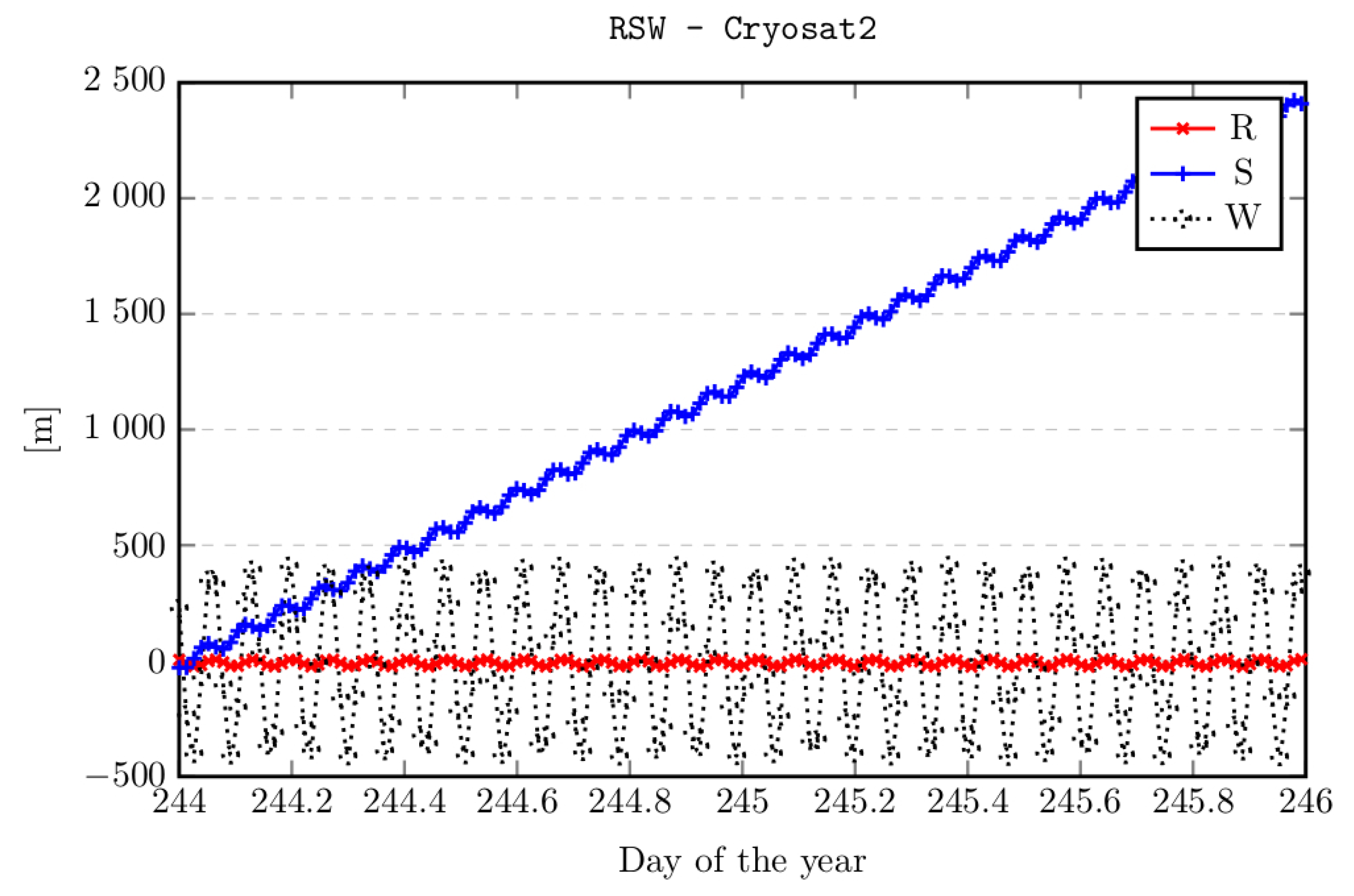
). However, in most cases, ephemerides are created on the basis of radar measurements (survey mode) and are made available in the form of TLE ephemerides with significant positional uncertainty. The TLE ephemeris for any moment of time
is calculated on the basis of the given orbit parameters together with their initial epoch
, therefore, unlike the ephemeris of the CPF type, software calculations are necessary to determine the values of
. The uncertainty of the orbit predicted on the basis of the TLE ephemeris compared to the orbit interpolated from the ephemeris of the CPF type is shown in
Figure 3.
Here, attention should be paid to the change in the quality of ephemeris over time. In the case of objects from the LEO region, the orbit parameters change due to the influence of the atmosphere and gravity (
Figure 4) [
16]. Therefore, to properly track an orbital object, it is necessary to use the current ephemeris data.
2.3. Laser Beam Propagation
An issue directly related to the laser measurement of the distance to an orbital object is the geometric shape of the laser beam. The laser distance measurement is based on the emission of a laser pulse towards the orbital object, where some of the photons are scattered from the object’s surface. The moment of time when the returning photons are acquired in the photon detector ends the measurement procedure (
Figure 5).
As described in the Introduction, orbital objects subject to the range measurements by the SLR stations are divided into cooperative and uncooperative ones. Cooperative targets are equipped with retroreflectors mounted on the outer casing. A special feature of the solution is the ability to reflect the laser beam towards the point of its emission. Accordingly, there is no need to generate a high-energy laser beam in order to obtain a photon event caused by scattering from the measured object. Uncooperative targets are therefore all other orbital objects that are not equipped with retroreflectors. Therefore, in order to achieve photon events from an uncooperative orbital object, high-energy laser sources and highly sensitive photon detectors must be used [
17,
18].
2.3.1. Beam Divergence
Each pulsed laser source is defined by the physical parameters, among which we distinguish: pulse energy (μJ, mJ), pulse width (ps, ns), repetition (Hz, kHz), beam divergence (mrad). With reference to Degnan’s radar link equation (Equation (
1)) [
19], the probability of registering a photon scattered from an orbital object strongly depends on the energy of the laser pulse and laser beam divergence. This dependence is as follows:
where
is the detector quantum efficiency,
is the laser pulse energy,
is the laser wavelength,
h is Planck’s constant,
c is the velocity of light in a vacuum,
is the transmit optics’ efficiency,
is the transmit gain,
is the orbital object cross-section,
R is the slant range to the object,
is the effective area of the telescope receive aperture,
is the efficiency of the receive optics,
is the one-way atmospheric transmission, and
is the one-way transmissivity of cirrus clouds (when present). The transmitter gain
of the system with the use of a Gaussian laser beam is defined as:
where
is half of the divergence angle between the axis of the laser beam and the area of intensity 1/
and
is the error of the positioning uncertainty of the emitted beam.
The geometrical divergence defines the degree of enlargement of the cross-sectional area of the laser beam with the distance and is expressed in mrad. Laser measurements are made for orbital objects from the regions from LEO to GEO, so the distance between the SLR station and the orbital object ranges from about 350 km to 42,000 km. The aim of the measurement process is to propagate the laser beam between the ground station and the orbital object. The laser source emits a laser beam with given physical parameters and a known starting diameter, which is usually a few millimeters (<1 cm) in size. Taking into account the large distance separating the ground station and the orbital object (>350 km), the geometric divergence parameter of the beam determines its cross-section size on the orbit. Standard laser sources for SLR needs are characterized by a geometric divergence of the beam at the level of 0.5 mrad–1.0 mrad (1.0 mrad = 206.26 arcsec). Assuming a 1 cm diameter of the laser beam with a divergence of 1 mrad, for an orbital object distance of 350 km, the orbital beam’s cross-sectional area is 700 m (for a 42,000 km distance, it is 84 km). This fact is of no great importance when tracking of cooperative objects with low-energy laser emission sources. The energy density that is deposited at a given orbital altitude in this case is not critical. However, in the case of tracking of uncooperative objects in order to obtain a photon event in the form of scattering a portion of light from the object and its subsequent detection, a high energy density deposited on the object’s surface is required. Therefore, it forces the use of systems correcting the divergence of the laser beam. Such a system is classically composed of a set of lenses for which the distance relation between them affects the final beam divergence. In this way, it is possible to correct the divergence parameter to a minimum value of
. For example, when using the divergence correction system, assuming a 1 cm diameter of the output laser beam with a divergence of 0.02 mrad, for a distance of the orbital object of 350 km, the cross-sectional size of the beam on the orbit is 14 m (for 42,000 km, it is 1.6 km, respectively). Such a divergence value guarantees a high energy density, which is necessary to acquire a detected photon event from an uncooperative object. However, such a divergence value combined with the ephemeris uncertainty described in
Section 2.2 may lead to acquisition difficulties. The relatively small cross-section of the laser beam on the orbit in the form of the spot size and an ephemeris with high uncertainty may prevent effective spot measurement of the object.
2.3.2. Coordination of Beam Emission
The classic SLR system consists of a receiving telescope, mostly in the
configuration, with a photon detector and a coaxially mounted laser beam emitter with a divergence corrector (
Figure 1). Depending on the type of the laser, it is possible to mount the laser source directly on the telescope housing or, in the case of the scientific lasers with a picosecond pulse width, there is a need to propagate the laser beam from an air-conditioned room, using the Coudé path with intermediary mirrors. Each solution ensures the alignment of the telescope axis with the laser beam emitter. Unfortunately, the imperfection of the ephemerides described in
Section 2.2 and the impact of laser beam divergence on the effectiveness of the measurement described in
Section 2.3.1 requires the correction of the telescope’s movement in order to frame the object. Ephemeris uncertainty is mainly related to the time shift along the object’s trajectory (along-track) and is determined by the TimeBias parameter. In the case of cooperative satellites, this parameter is determined by other SLR stations during previous measurements. In this way, it is possible to make an appropriate time correction before starting the tracking process. A large number of uncooperative objects makes it impossible to determine the value of this parameter. In such a case, a movable prismatic head in the
XY plane system can be used behind the laser source output. This solution enables manual or automatic angular offset of the laser beam in relation to the telescope’s axes. Laser measurement only determines the distance to the object in the time domain; therefore, the angular offset of the laser beam does not cause disturbances to the results.
5. Conclusions
The process of the laser ranging measurement of orbital objects with the uncertain ephemerides is a difficult issue. Besides, the growing amount of space debris forces the use of new solutions to maximize information about the orbits of such objects. The available number of laser tracking sensors is too small to improve the quality of the orbits obtained from radar survey sensors. This paper proposed solutions to improve the effectiveness of measuring the distance to the orbital objects with uncertain orbits using the active control loop implemented at the Borowiec SLR station. The presented algorithms for the active correction of mount motion control and automatic object search functionality led to an increase in the effectiveness of measuring objects such as space debris. Cooperative objects are only a small subset of the space debris population, so these objects should be treated as uncooperative targets in terms of the measurements based on the TLE ephemeris. An additional advantage of these solutions is the ability to perform measurements in automatic mode, which with 24/7 operations relieves the need for the SLR station operator. Further research is needed to optimize the proposed solutions, which depend on the type of object and the orbital regime. Depending on the capabilities of a given laser station, it is possible to carry out detailed analyses with the implementation of the described algorithms. The proposed analyses may refer to the detection of the coordinate offset values of a specific orbital object on the basis of information stored in the database. Such information can be gathered from previous observations of an orbital object using the photon event active control loop or passive optical acquisition active control loop algorithms. The obtained and averaged value of the positional offset stored in the database may be the starting point to perform a new observation of the given orbital object. The analysis can be made taking into account the type of ephemerides (TLE, CPF), the orbital altitude, as well as the suitability of ephemeris use depending on the epoch of its generation. Another aspect that can be investigated is the analysis of the required beam divergence in order to find the object in the initial phase. Such an analysis can be performed for object types (e.g., rocket bodies), as well as individually for a specific orbital object. Furthermore, a quantitative statistic of photon events for a specific object can be made. In this way, it will be possible to determine the effectiveness of subsequent observations during the target search process. A separate issue is the parameterization of algorithms, which depends on the specific configuration of the laser sensor. The parameters of the receiving telescope, including the photon detector, and the telescope mount motion control loop are of importance here. Commissioning of the second SLR system at Borowiec Astrogeodynamic Observatory based on a dedicated laser and photon detector will allow for many analyses taking into account the impact of ephemeris uncertainty on the reaction time of the SLR system and the obtained results. Optimizing the operation of algorithms during daytime observations is not without significance, which will be the next stage of the research. The effectiveness of the proposed solutions can be verified only in the conditions of the availability of a measuring laser and a photon detector. Only in this way, by obtaining the reflections from the orbital object, will it be possible to determine the effectiveness of the operating algorithms.


