
Localization of Stereovision for Measuring In-Crash Toeboard Deformation


Abstract
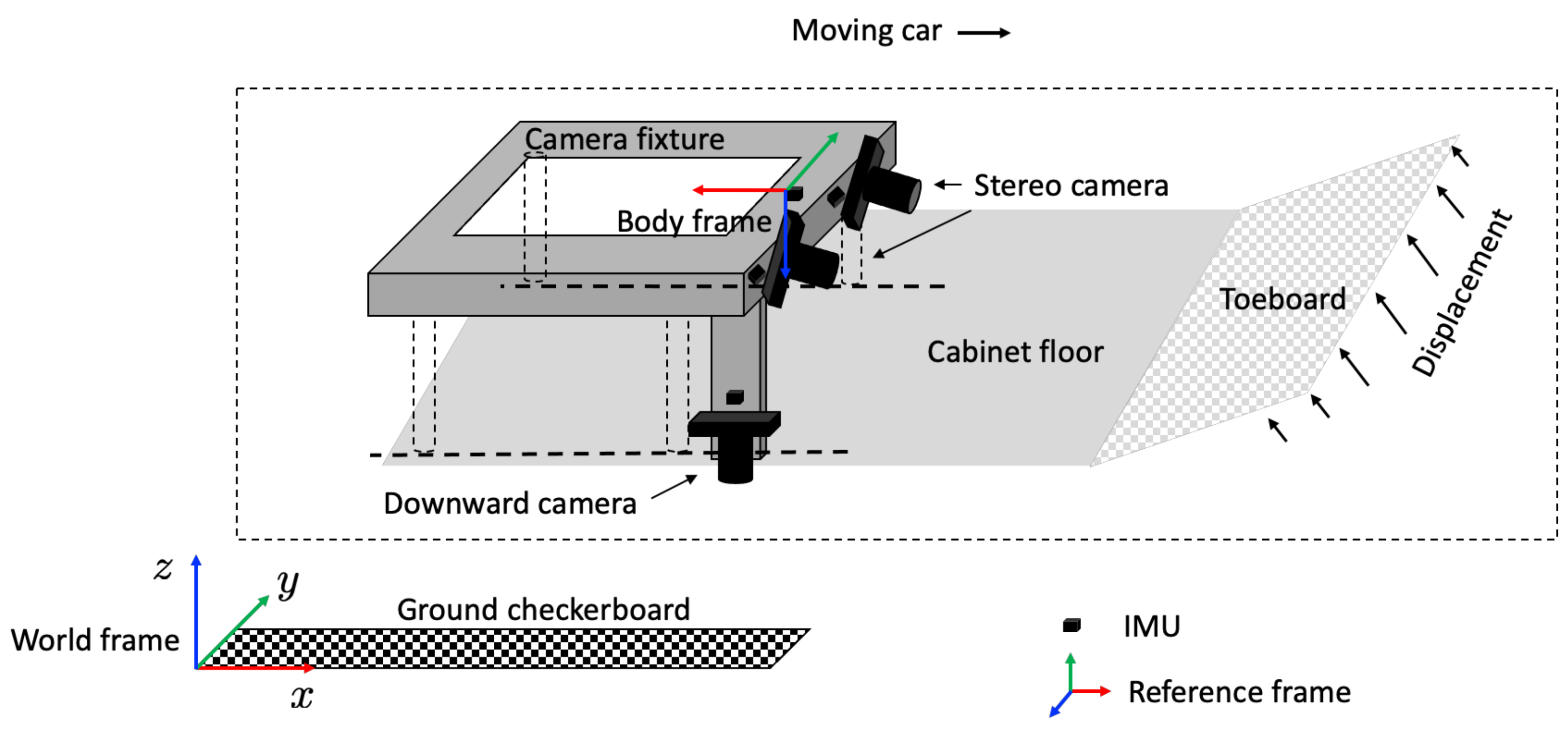
:1. Introduction
2. Sensor Suite and Localization Problem of Stereovision
2.1. Problem Formulation
2.2. Linear Acceleration of Sensor Suite
2.3. Localization of Downward Camera

3. EKF-Based Localization of Stereo Camera for Toeboard Measurement
3.1. Overview
3.2. Motion Model of Sensor Suite
3.3. Sensor Models for Localization of Sensor Suite
3.3.1. Sensor Models of Accelerometer
3.3.2. Sensor Models of Gyroscope
3.3.3. Sensor Models for Angular Acceleration
3.3.4. Sensor Model of Downward Camera
3.4. EKF
4. Sensor Suite Design and Installation
5. Experimental Results
5.1. Sensor Suite Localization in Simulated Environment


5.2. Sensor Suite Localization in 56 km/h Frontal Barrier Car Crash Test
5.2.1. Pose Estimation of Downward Camera
5.2.2. Localization of Sensor Suite

6. Conclusions and Ongoing Work
Author Contributions
Funding
Data Availability Statement
Acknowledgments
Conflicts of Interest
References
- NHTSA. Motor vehicle crashes: Overview. Traffic Saf. Facts Res. Note 2016, 2016, 1–9. [Google Scholar]
- Kim, H.; Hong, S.; Hong, S.; Huh, H.; Motors, K.; Kwangmyung Shi, K. The evaluation of crashworthiness of vehicles with forming effect. In Proceedings of the 4th European LS-DYNA Users Conference, Ulm, Germany, 22–23 May 2003; pp. 25–34. [Google Scholar]
- Mehdizadeh, A.; Cai, M.; Hu, Q.; Alamdar Yazdi, M.A.; Mohabbati-Kalejahi, N.; Vinel, A.; Rigdon, S.E.; Davis, K.C.; Megahed, F.M. A review of data analytic applications in road traffic safety. Part 1: Descriptive and predictive modeling. Sensors 2020, 20, 1107. [Google Scholar] [CrossRef] [PubMed] [Green Version]
- Wei, Z.; Karimi, H.R.; Robbersmyr, K.G. Analysis of the Relationship between Energy Absorbing Components and Vehicle Crash Response; SAE Technical Paper Series; SAE International: Warrendale, PA, USA, 2016; Volume 4. [Google Scholar]
- Górniak, A.; Matla, J.; Górniak, W.; Magdziak-Tokłowicz, M.; Krakowian, K.; Zawiślak, M.; Włostowski, R.; Cebula, J. Influence of a passenger position seating on recline seat on a head injury during a frontal crash. Sensors 2022, 22, 2003. [Google Scholar] [CrossRef] [PubMed]
- Varat, M.S.; Husher, S.E. Vehicle crash severity assessment in lateral pole impacts. SAE Trans. 1999, 108, 302–324. [Google Scholar]
- Song, M.; Chen, C.; Furukawa, T.; Nakata, A.; Shibata, S. A sensor suite for toeboard three-dimensional deformation measurement during crash. Stapp Car Crash J. 2019, 63, 331–342. [Google Scholar]
- Nakata, A.; Furukawa, T.; Shibata, S.; Hashimoto, T. Development of Chronological Measurement Method of Three-Dimensional Toe Board Deformation During Frontal Crash. Trans. Soc. Automot. Eng. Jpn. 2021, 52, 1131–1136. [Google Scholar]
- Austin, R.A. Lower extremity injuries and intrusion in frontal crashes. Accid. Reconstr. J. 2013, 23, 1–23. [Google Scholar]
- Patalak, J.P.; Stitzel, J.D. Evaluation of the effectiveness of toe board energy-absorbing material for foot, ankle, and lower leg injury reduction. Traffic Inj. Prev. 2018, 19, 195–200. [Google Scholar] [CrossRef]
- Hu, Y.; Liu, X.; Neal-Sturgess, C.E.; Jiang, C.Y. Lower leg injury simulation for EuroNCAP compliance. Int. J. Crashworthiness 2011, 16, 275–284. [Google Scholar] [CrossRef]
- Lin, C.S.; Chou, K.D.; Yu, C.C. Numerical simulation of vehicle crashes. Appl. Mech. Mater. 2014, 590, 135–143. [Google Scholar] [CrossRef]
- Saha, N.K.; Wang, H.C.; El-Achkar, R. Frontal offset pole impact simulation of automotive vehicles. In Proceedings of the International Computers in Engineering Conference and Exposition, San Francisco, CA, USA, 2–6 August 1992; pp. 203–207. [Google Scholar]
- Bathe, K.J. Crash simulation of cars with finite element analysis. Mech. Eng. Mag. Sel. Artic. 1998, 120, 82–83. [Google Scholar]
- Omar, T.; Eskandarian, A.; Bedewi, N. Vehicle crash modelling using recurrent neural networks. Math. Comput. Model. 1998, 28, 31–42. [Google Scholar] [CrossRef]
- Hickey, A.; Xiao, S. Finite Element Modeling and Simulation of Car Crash. Int. J. Mod. Stud. Mech. Eng. 2017, 3, 1–5. [Google Scholar]
- Yang, R.J.; Wang, N.; Tho, C.H.; Bobineau, J.P.; Wang, B.P. Metamodeling development for vehicle frontal impact simulation. J. Mech. Des. 2005, 127, 1014–1020. [Google Scholar] [CrossRef]
- Cheng, Z.Q.; Thacker, J.G.; Pilkey, W.D.; Hollowell, W.T.; Reagan, S.W.; Sieveka, E.M. Experiences in reverse-engineering of a finite element automobile crash model. Finite Elem. Anal. Des. 2001, 37, 843–860. [Google Scholar] [CrossRef]
- McClenathan, R.V.; Nakhla, S.S.; McCoy, R.W.; Chou, C.C. Use of photogrammetry in extracting 3d structural deformation/dummy occupant movement time history during vehicle crashes. SAE Trans. 2005, 1, 736–742. [Google Scholar]
- Zhang, X.Y.; Jin, X.L.; Qi, W.; Sun, Y. Virtual reconstruction of vehicle crash accident based on elastic-plastic deformation of auto-body. In Key Engineering Materials; Trans Tech Publications Ltd.: Bäch SZ, Switzerland, 2004; Volume 274, pp. 1017–1022. [Google Scholar]
- Pan, B. Digital image correlation for surface deformation measurement: Historical developments, recent advances and future goals. Meas. Sci. Technol. 2018, 29, 1–33. [Google Scholar] [CrossRef]
- Ghorbani, R.; Matta, F.; Sutton, M.A. Full-field deformation measurement and crack mapping on confined masonry walls using digital image correlation. Exp. Mech. 2015, 55, 227–243. [Google Scholar] [CrossRef]
- Scaioni, M.; Feng, T.; Barazzetti, L.; Previtali, M.; Roncella, R. Image-based deformation measurement. Appl. Geomat. 2015, 7, 75–90. [Google Scholar] [CrossRef] [Green Version]
- Chen, F.; Chen, X.; Xie, X.; Feng, X.; Yang, L. Full-field 3D dimensional measurement using multi-camera digital image correlation system. Opt. Lasers Eng. 2013, 51, 1044–1052. [Google Scholar] [CrossRef]
- Lichtenberger, R.; Schreier, H.; Ziegahn, K. Non-contacting measurement technology for component safety assessment. In Proceedings of the 6th International Symposium and Exhibition on Sophisticated Car Occupant Safety Systems (AIRBAG’02), Karlsruhe, Germany, 6–8 December 2002. [Google Scholar]
- Sutton, M.A.; Mingqi, C.; Peters, W.H.; Chao, Y.J.; McNeill, S.R. Application of an optimized digital correlation method to planar deformation analysis. Image Vis. Comput. 1986, 4, 143–150. [Google Scholar] [CrossRef]
- Chu, T.; Ranson, W.; Sutton, M.A. Applications of digital-image-correlation techniques to experimental mechanics. Exp. Mech. 1985, 25, 232–244. [Google Scholar] [CrossRef]
- De Domenico, D.; Quattrocchi, A.; Alizzio, D.; Montanini, R.; Urso, S.; Ricciardi, G.; Recupero, A. Experimental characterization of the FRCM-concrete interface bond behavior assisted by digital image correlation. Sensors 2021, 21, 1154. [Google Scholar] [CrossRef] [PubMed]
- Bardakov, V.V.; Marchenkov, A.Y.; Poroykov, A.Y.; Machikhin, A.S.; Sharikova, M.O.; Meleshko, N.V. Feasibility of digital image correlation for fatigue cracks detection under dynamic loading. Sensors 2021, 21, 6457. [Google Scholar] [CrossRef]
- Chou, J.Y.; Chang, C.M. Image motion extraction of structures using computer vision techniques: A comparative study. Sensors 2021, 21, 6248. [Google Scholar] [CrossRef]
- Xiong, B.; Zhang, Q.; Baltazart, V. On quadratic interpolation of image cross-correlation for subpixel motion extraction. Sensors 2022, 22, 1274. [Google Scholar] [CrossRef]
- Schmidt, T.E.; Tyson, J.; Galanulis, K.; Revilock, D.M.; Melis, M.E. Full-field dynamic deformation and strain measurements using high-speed digital cameras. In Proceedings of the 26th International Congress on High-Speed Photography and Photonics, Alexandria, VA, USA, 20–24 September 2004; pp. 174–185. [Google Scholar]
- Iliopoulos, A.P.; Michopoulos, J.; Andrianopoulos, N.P. Performance sensitivity analysis of the mesh-free random grid method for whole field strain measurements. In Proceedings of the International Design Engineering Technical Conferences and Computers and Information in Engineering Conference, Brooklyn, NY, USA, 3–6 August 2008; pp. 545–555. [Google Scholar]
- Furukawa, T.; Pan, J.W. Stochastic identification of elastic constants for anisotropic materials. Int. J. Numer. Methods Eng. 2010, 81, 429–452. [Google Scholar] [CrossRef]
- Schweppe, F. Recursive state estimation: Unknown but bounded errors and system inputs. IEEE Trans. Autom. Control. 1968, 13, 22–28. [Google Scholar] [CrossRef]
- Vargas-Melendez, L.; Boada, B.L.; Boada, M.J.L.; Gauchia, A.; Diaz, V. Sensor fusion based on an integrated neural network and probability density function (PDF) dual Kalman filter for on-line estimation of vehicle parameters and states. Sensors 2017, 17, 987. [Google Scholar] [CrossRef]
- Qu, L.; Dailey, M.N. Vehicle trajectory estimation based on fusion of visual motion features and deep learning. Sensors 2021, 21, 7969. [Google Scholar] [CrossRef]
- Zhang, Z. A flexible new technique for camera calibration. IEEE Trans. Pattern Anal. Mach. Intell. 2000, 22, 1330–1334. [Google Scholar] [CrossRef] [Green Version]
- Heikkila, J.; Silvén, O. A four-step camera calibration procedure with implicit image correction. In Proceedings of the IEEE Computer Society Conference on Computer Vision and Pattern Recognition, San Juan, PR, USA, 17–19 June 1997; pp. 1106–1112. [Google Scholar]
- Bouguet, J.Y. Camera Calibration Toolbox for matlab. Available online: http://robots.stanford.edu/cs223b04/JeanYvesCalib/htmls/links.html (accessed on 7 April 2022).
- Diebel, J. Representing attitude: Euler angles, unit quaternions, and rotation vectors. Matrix 2006, 58, 1–35. [Google Scholar]
- Willner, D.; Chang, C.B.; Dunn, K.P. Kalman Filter Configurations for Multiple Radar Systems; Technical Report; MIT Lexington Lincoln Laboratory: Lexington, MA, USA, 1976. [Google Scholar]


| Inertial sensors sampling rate | 20,000 Hz |
| Accelerometer noise | |
| Accelerometer range | |
| Gyroscope noise noise | |
| Gyroscope range | 18,000 |
| Camera sampling rate | |
| Camera resolution | |
| Downward camera to the ground | |
| Target toeboard size |
Publisher’s Note: MDPI stays neutral with regard to jurisdictional claims in published maps and institutional affiliations. |
© 2022 by the authors. Licensee MDPI, Basel, Switzerland. This article is an open access article distributed under the terms and conditions of the Creative Commons Attribution (CC BY) license (https://creativecommons.org/licenses/by/4.0/).
Share and Cite
Zhang, W.; Furukawa, T.; Nakata, A.; Hashimoto, T. Localization of Stereovision for Measuring In-Crash Toeboard Deformation. Sensors 2022, 22, 2962. https://doi.org/10.3390/s22082962
Zhang W, Furukawa T, Nakata A, Hashimoto T. Localization of Stereovision for Measuring In-Crash Toeboard Deformation. Sensors. 2022; 22(8):2962. https://doi.org/10.3390/s22082962
Chicago/Turabian StyleZhang, Wei, Tomonari Furukawa, Azusa Nakata, and Toru Hashimoto. 2022. "Localization of Stereovision for Measuring In-Crash Toeboard Deformation" Sensors 22, no. 8: 2962. https://doi.org/10.3390/s22082962
APA StyleZhang, W., Furukawa, T., Nakata, A., & Hashimoto, T. (2022). Localization of Stereovision for Measuring In-Crash Toeboard Deformation. Sensors, 22(8), 2962. https://doi.org/10.3390/s22082962