
Active Disturbance Rejection Control in Magnetic Bearing Rotor Systems with Redundant Structures

 ,
, 

Abstract
:1. Introduction
2. Mathematical Model of Magnetic Bearing with Redundant Structures
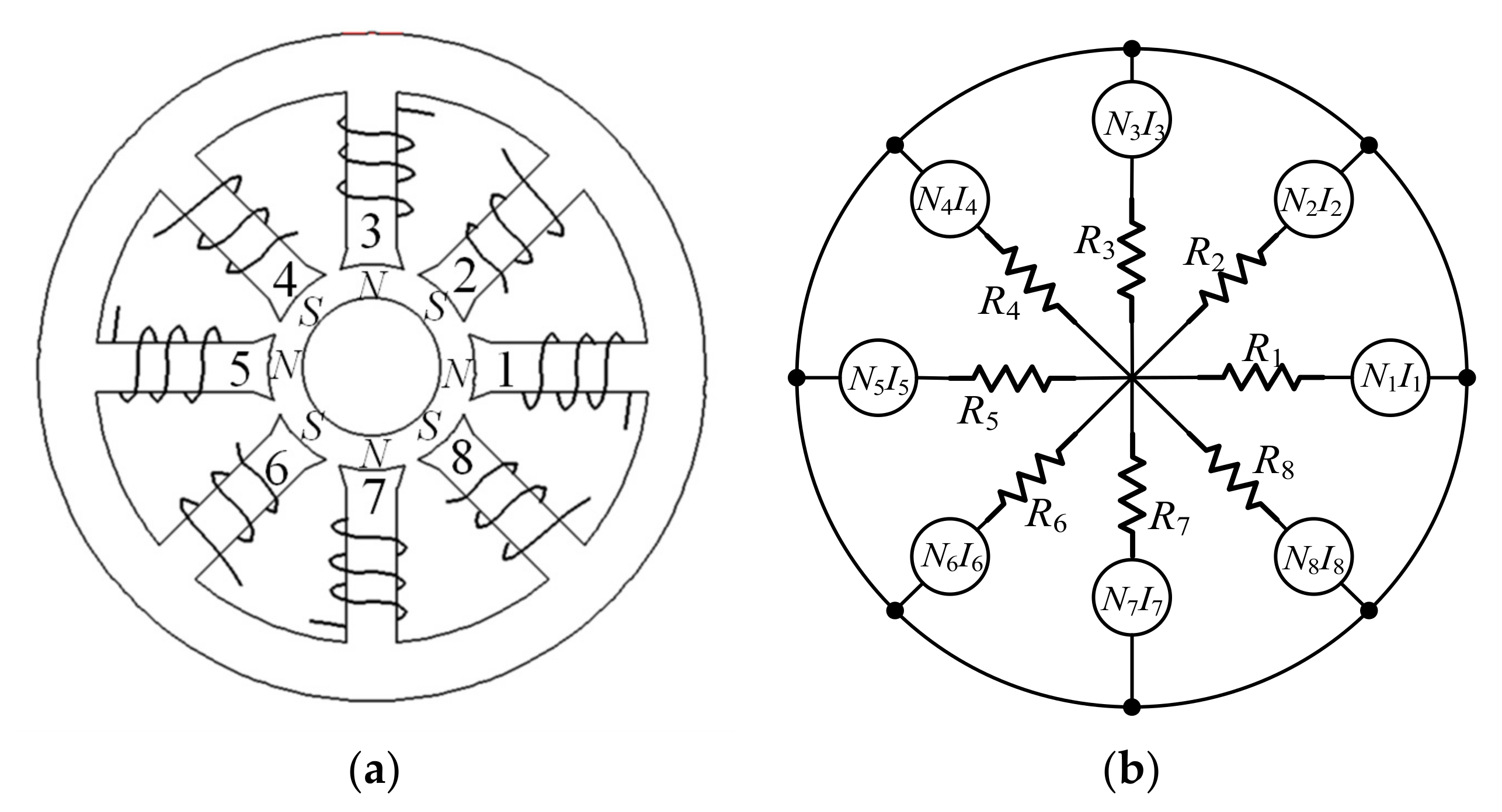
2.1. Theory of Eight-Pole Magnetic Bearings with Redundant Structures
2.2. Linearized Forces with Stiffness Model of Magnetic Bearings with Redundant Structures
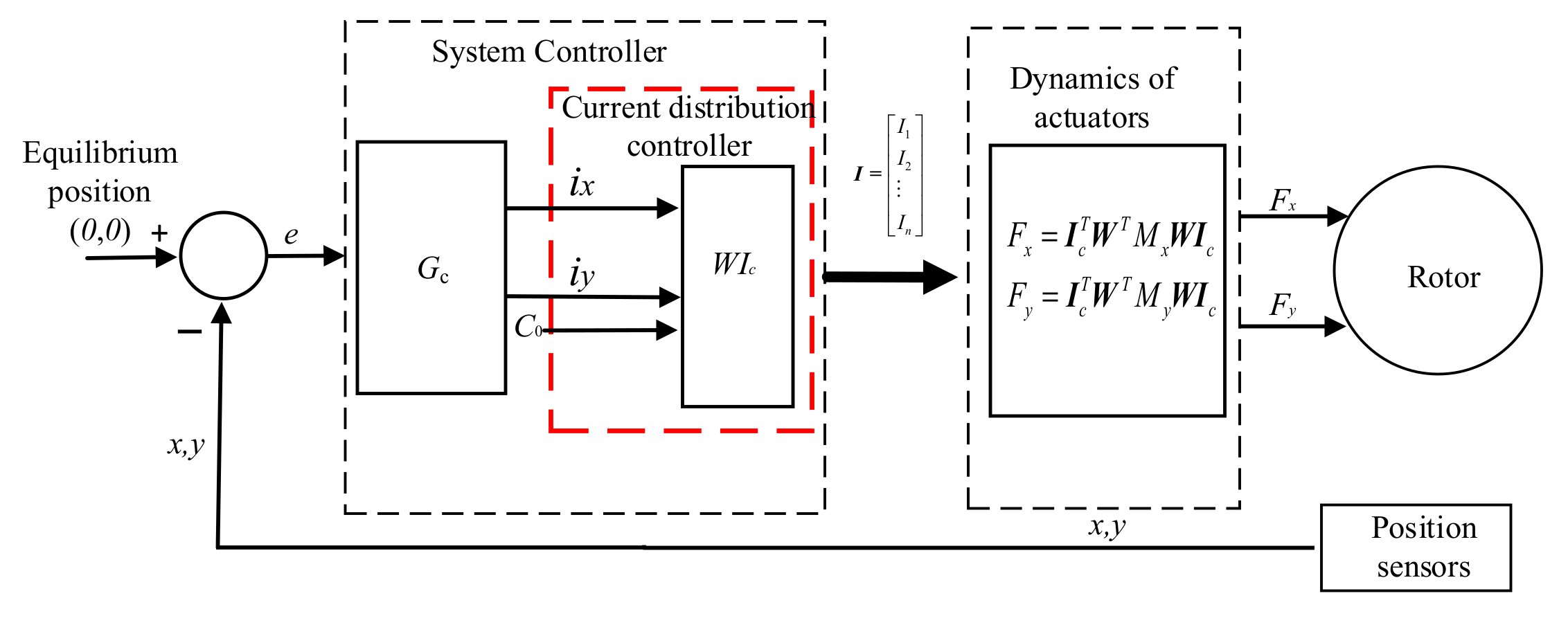
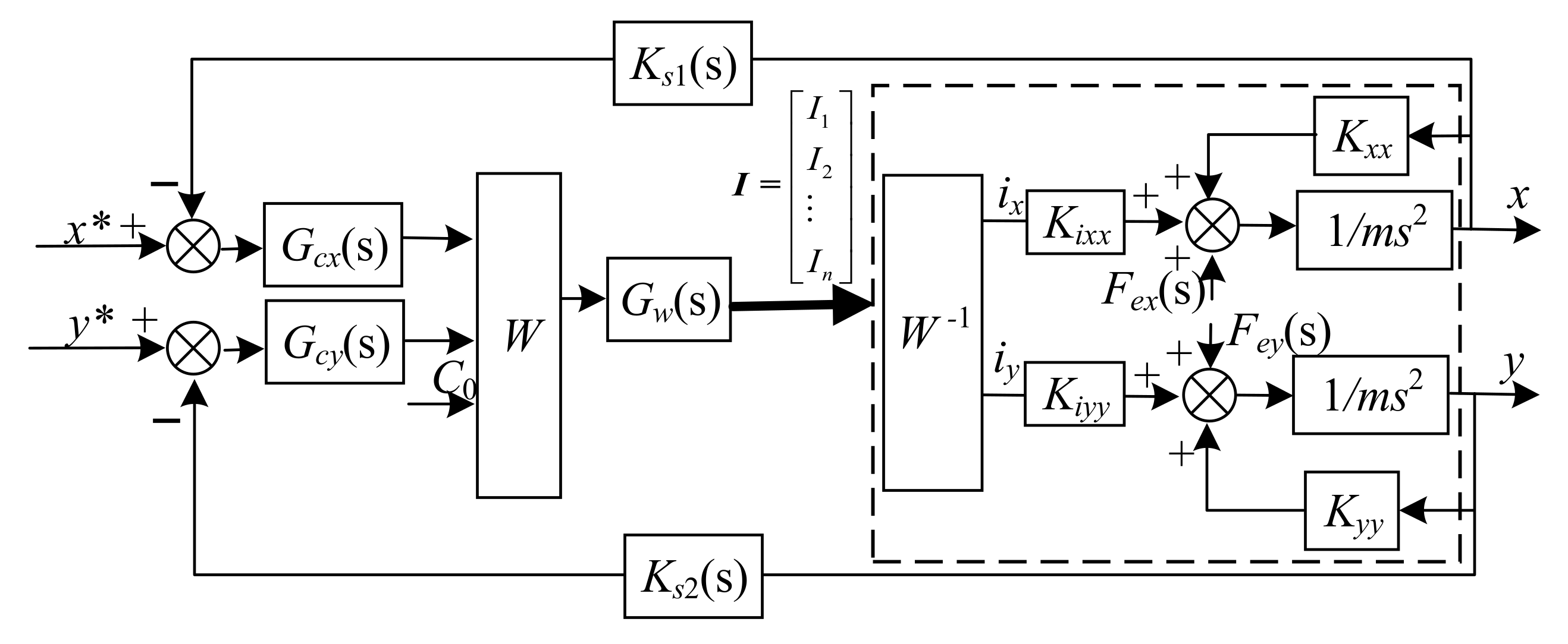
2.3. Equivalent Control Strategy of Magnetic Bearings with Redundant Structures
3. Design of ADRC for AMB with Redundant Structures
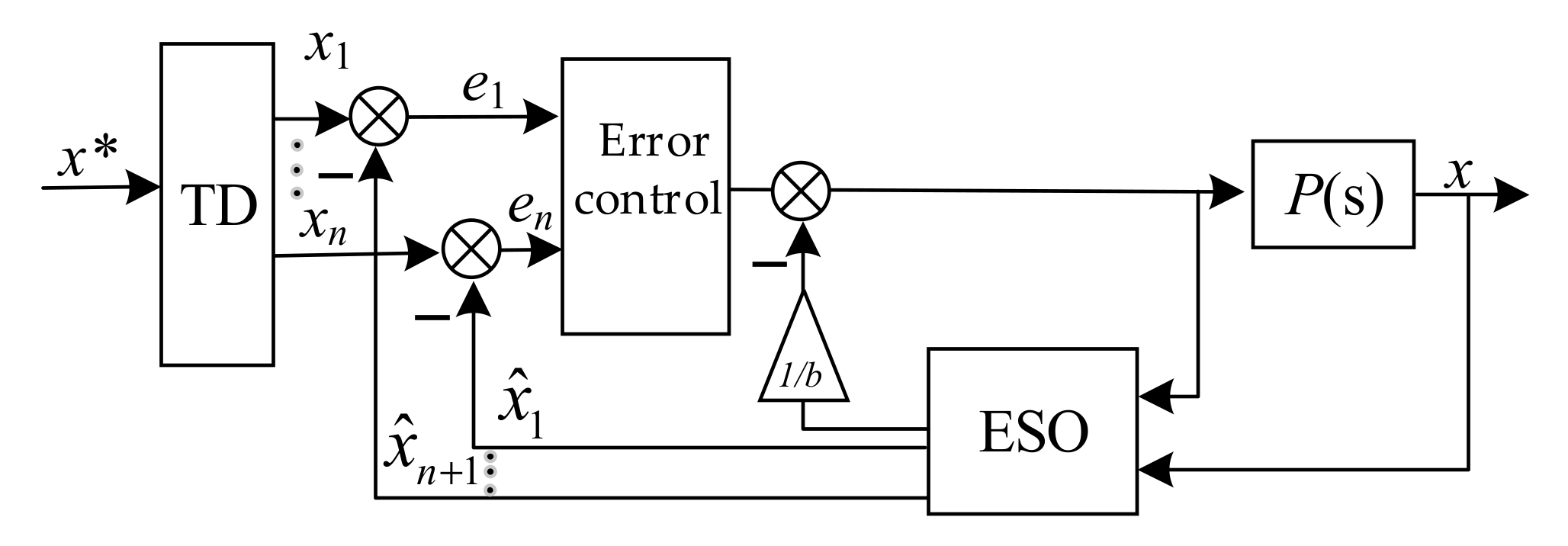
3.1. Basic Theory and Structure of ADRC
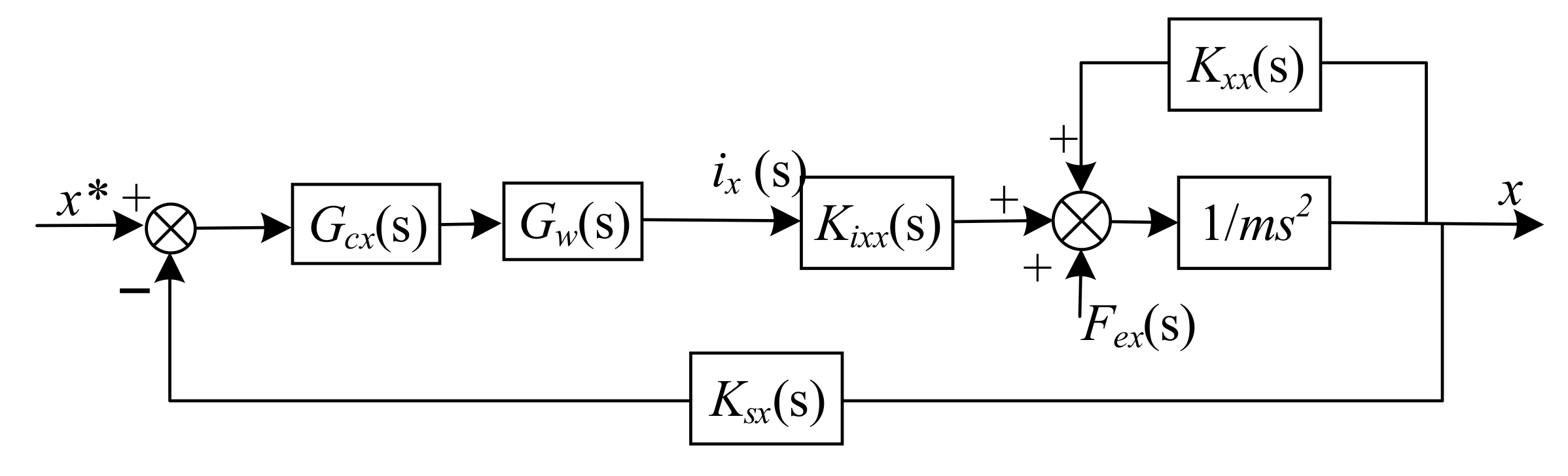
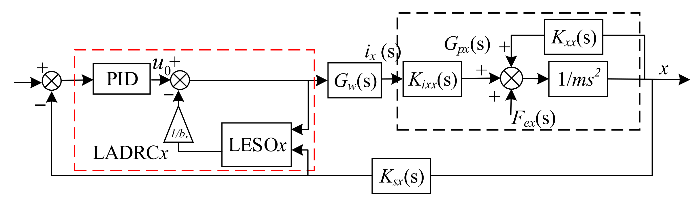
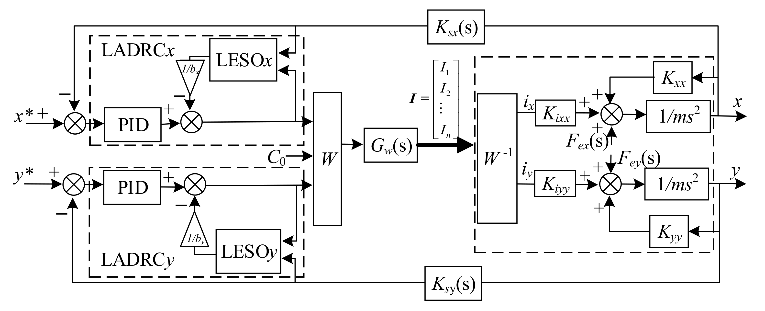
3.2. Design of the LADRC for the AMB with Redundant Structures
4. Simulation and Analysis
5. Conclusions
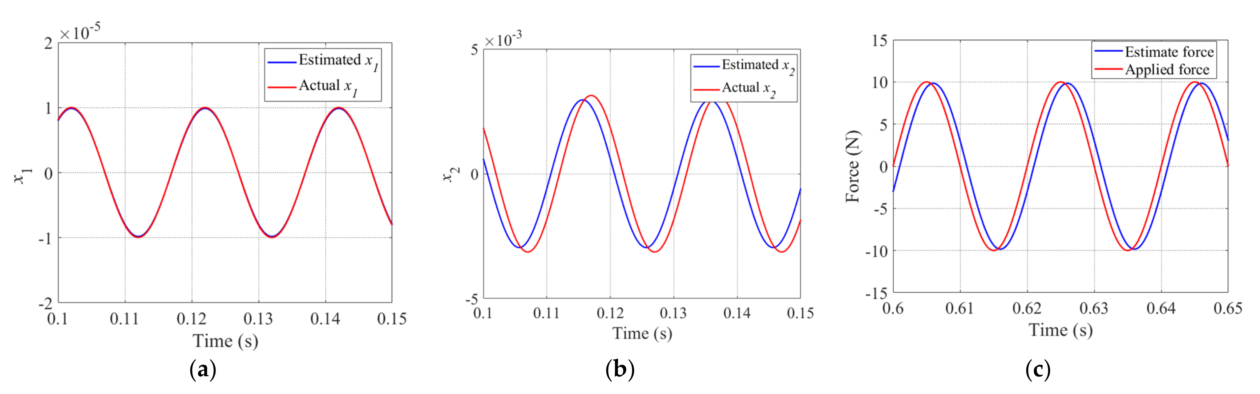
- (1)
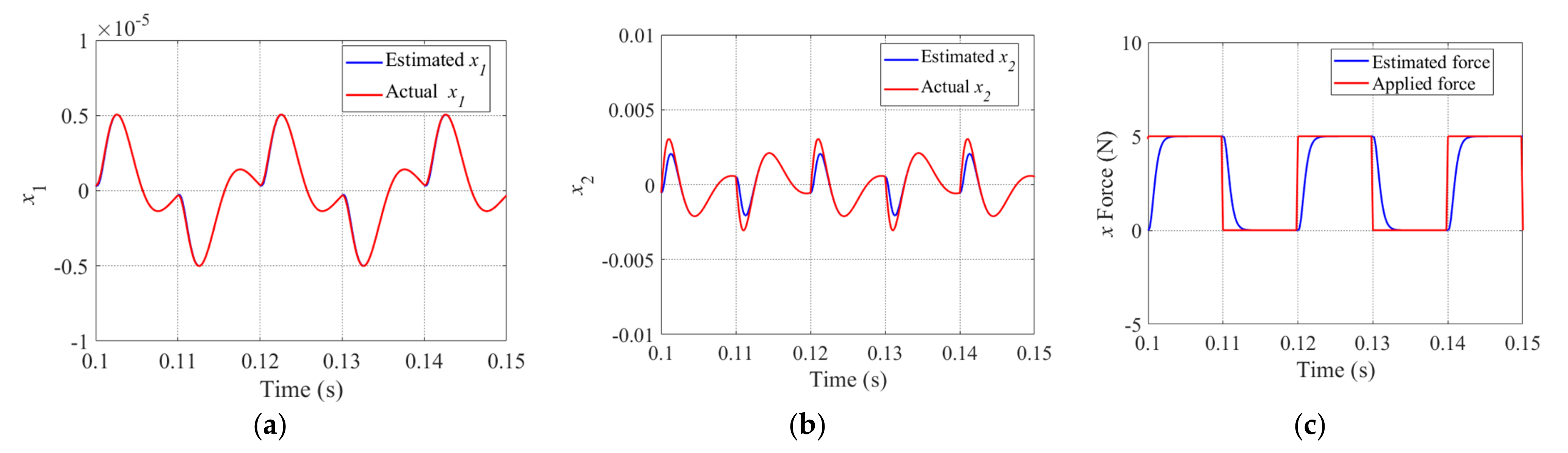
- While the periodic step disturbance or sinusoidal disturbance is acting on the system, the linear extended state observers LESOx and LESOy, designed for the x and y directions, respectively, demonstrated good estimation and tracking performance; in particular, the LESO was able to estimate most of the disturbance values in real time. It provides an effective value of disturbance for the compensator of the LADRC, thus ensuring the performance of the LADRC.
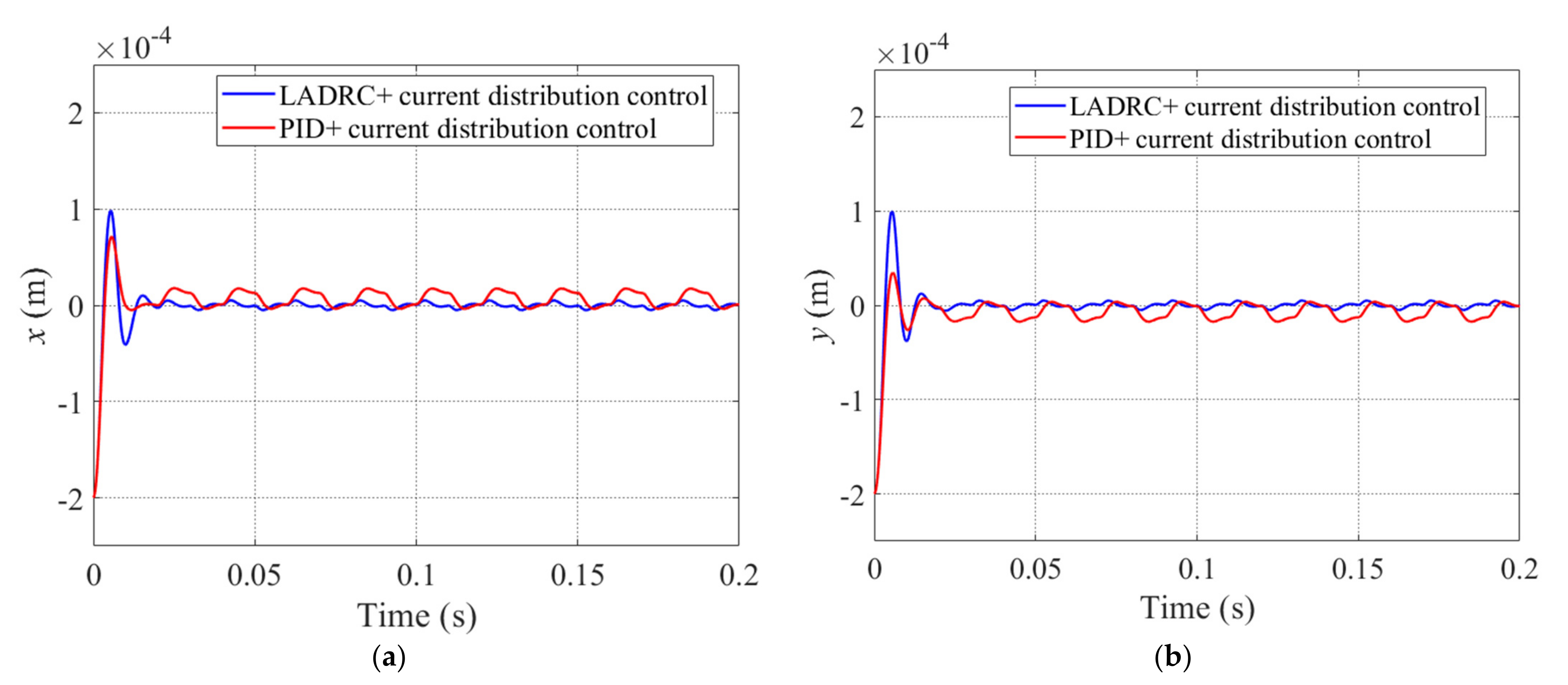
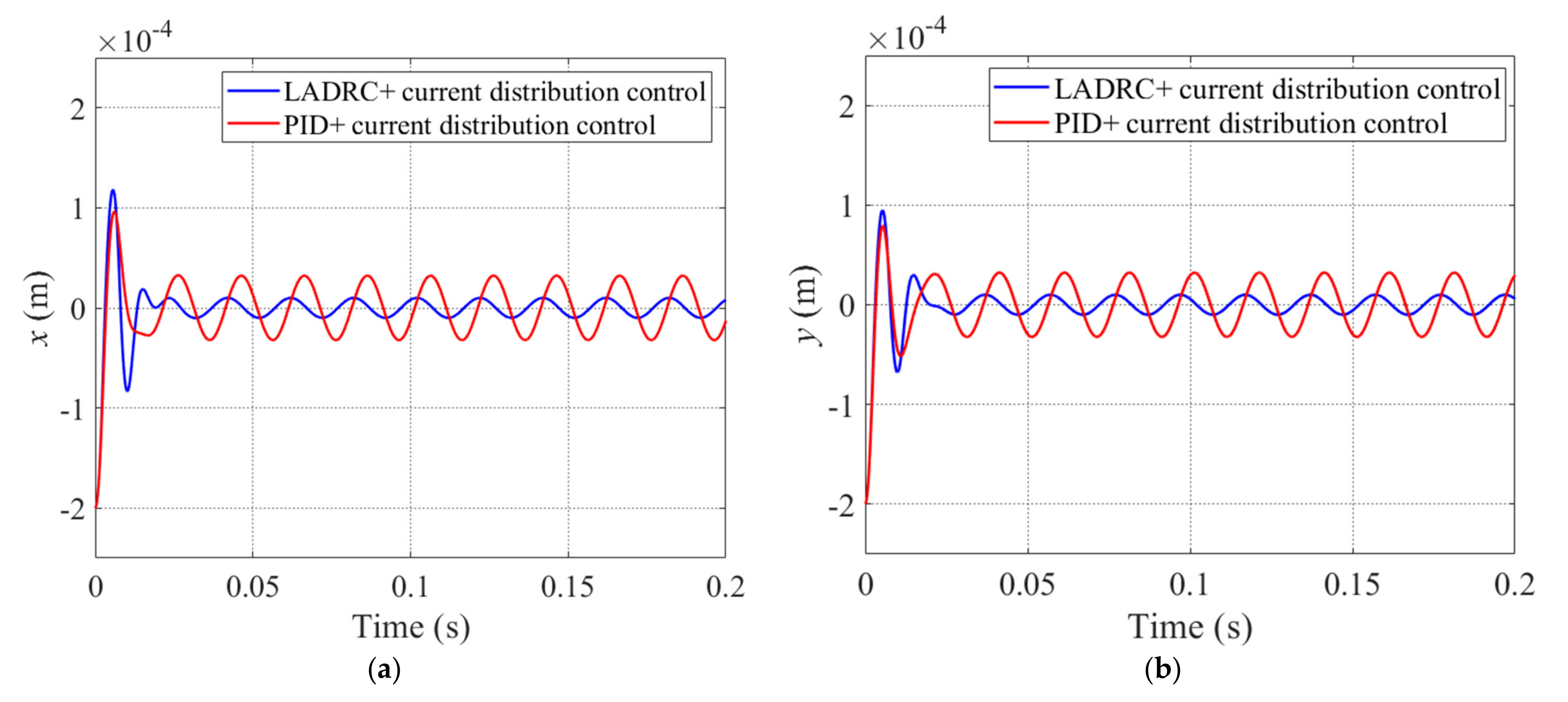
- (2)
- For the periodic step disturbance or sinusoidal disturbance of the magnetic bearing–rotor system, compared with the PID+current distribution control, while the rotor is suspended, the maximum vibration displacement of the rotor was attenuated by 70%. The rotor suspension accuracy was greatly improved by using LADRC+current distribution control.
Author Contributions
Funding
Institutional Review Board Statement
Informed Consent Statement
Data Availability Statement
Conflicts of Interest
References
- Zhang, Y.; Tang, J.; Xu, X.; Huang, Z. Optimal design of magnetically suspended high-speed rotor in turbo-molecular pump. Vacuum 2021, 193, 110510. [Google Scholar] [CrossRef]
- Cui, P.; Li, S.; Zhao, G.; Peng, C. Suppression of Harmonic Current in Active–Passive Magnetically Suspended CMG Using Improved Repetitive Controller. IEEE/ASME Trans. Mechatron. 2016, 21, 2132–2141. [Google Scholar] [CrossRef]
- Han, B.; Xu, Q.; Yuan, Q. Multiobjective Optimization of a Combined Radial-Axial Magnetic Bearing for Magnetically Suspended Compressor. IEEE Trans. Ind. Electron. 2016, 63, 2284–2293. [Google Scholar] [CrossRef]
- Li, X.; Palazzolo, A.; Wang, Z. A Combination 5-DOF Active Magnetic Bearing for Energy Storage Flywheels. IEEE Trans. Transp. Electrif. 2021, 7, 2344–2355. [Google Scholar] [CrossRef]
- Maslen, E.H.; Meeker, D.C. Fault tolerance of magnetic bearings by generalized bias current linearization. IEEE Trans. Magn. 1995, 31, 2304–2314. [Google Scholar] [CrossRef] [Green Version]
- Na, U.J.; Palazzolo, A. Optimized realization of fault-tolerant heteropolar magnetic bearings. J. Vib. Acoust. 2000, 122, 209–221. [Google Scholar] [CrossRef] [Green Version]
- Na, U.J.; Palazzolo, A.B.; Provenza, A. Test and theory correlation study for a flexible rotor on fault-tolerant magnetic bearings. J. Vib. Acoust. 2002, 124, 359–366. [Google Scholar] [CrossRef]
- Noh, M.D.; Cho, S.R.; Kyung, J.H.; Ro, S.K.; Park, J.K. Design and implementation of a fault-tolerant magnetic bearing system for Turbo-Molecular Vacuum Pump. IEEE/ASME Trans. Mechatron. 2005, 10, 626–631. [Google Scholar] [CrossRef]
- Meeker, D. A generalized unbiased control strategy for radial magnetic beatings. Actuators 2017, 6, 1. [Google Scholar] [CrossRef] [Green Version]
- Na, U.J.; Palazzolo, A.B. Fault tolerance of magnetic bearings with material path reluctances and fringing factors. IEEE Trans. Magn. 2000, 36, 3939–3946. [Google Scholar] [CrossRef] [Green Version]
- Na, U.J. Fault tolerant control of magnetic bearings with force invariance. KSME J. Mech. Sci. Technol. 2005, 19, 731–742. [Google Scholar] [CrossRef]
- Na, U.J. Fault tolerant homopolar magnetic bearings with flux invariant control. KSME J. Mech. Sci. Technol. 2006, 20, 643–651. [Google Scholar] [CrossRef]
- Xin, C.; Baixin, C.; Han, L.; Allen, G.M. An Accurate Linearization of Electromagnetic Force of Heteropolar Magnetic Bearings with Redundant Structures. J. Eng. Gas Turbines Power 2020, 142, 091002. [Google Scholar] [CrossRef]
- Cheng, B.; Cheng, X.; Song, S.; Deng, S.; Zhou, R.; Hu, Y.; Wu, H. Fault-Tolerant Control of Magnetically-Levitated Rotor with Redundant Structures Based on Improved Generalized Linearized EMFs Model. Sensors 2021, 21, 5404. [Google Scholar] [CrossRef]
- Cheng, X.; Deng, S.; Cheng, B.; Hu, Y.; Wu, H.; Zhou, R. Design and implementation of a fault-tolerant magnetic bearing control system combined with a novel fault-diagnosis of actuators. IEEE Access 2020, 9, 2454–2465. [Google Scholar] [CrossRef]
- Meeker, D.; Maslen, E. A Parametric Solution to the Generalized Bias Linearization Problem. Actuators 2020, 3, 4. [Google Scholar] [CrossRef] [Green Version]
- Cui, P.; He, J.; Fang, J. Static mass imbalance identification and vibration control for rotor of magnetically suspended control moment gyro with active-passive magnetic bearings. J. Vib. Control 2014, 22, 2313–2324. [Google Scholar] [CrossRef]
- Zhou, J.; Wu, H.; Wang, W.; Yang, K.; Hu, Y.; Guo, X.; Song, C. Online unbalance compensation of a maglev rotor with two active magnetic bearings based on the LMS algorithm and the influence coefficient method. Mech. Syst. Signal Process. 2022, 166, 108460. [Google Scholar] [CrossRef]
- Gallego, G.B.; Rossini, L.; Achtnich, T.; Araujo, D.M.; Perriard, Y. Novel Generalised Notch Filter for Harmonic Vibration Suppression in Magnetic Bearing Systems. IEEE Trans. Ind. Appl. 2021, 57, 6977–6987. [Google Scholar] [CrossRef]
- Cui, P.; Zhang, G.; Liu, Z.; Han, B.; Wang, Q. A Second-Order Dual Mode Repetitive Control for Magnetically Suspended Rotor. IEEE Trans. Ind. Electron. 2019, 67, 4946–4956. [Google Scholar] [CrossRef]
- Cui, P.; Wang, Q.; Zhang, G.; Gao, Q. Hybrid Fractional Repetitive Control for Magnetically Suspended Rotor Systems. IEEE Trans. Ind. Electron. 2017, 65, 3491–3498. [Google Scholar] [CrossRef]
- Cai, K.; Deng, Z.; Peng, C.; Li, K. Suppression of Harmonic Vibration in Magnetically Suspended Centrifugal Compressor Using Zero-Phase Odd-Harmonic Repetitive Controller. IEEE Trans. Ind. Electron. 2019, 67, 7789–7797. [Google Scholar] [CrossRef]
- Cui, P.; Du, L.; Zhou, X.; Li, J.; Li, Y.; Wu, Y. Harmonic vibration moment suppression using hybrid repetitive control for active magnetic bearing system. J. Vib. Control 2021. [Google Scholar] [CrossRef]
- Cui, P.; Li, S.; Wang, Q.; Gao, Q.; Cui, J.; Zhang, H. Harmonic current suppression of an AMB rotor system at variable rotation speed based on multiple phase-shift notch filters. IEEE Trans. Ind. Electron. 2016, 63, 6962–6969. [Google Scholar] [CrossRef]
- He, J.; Peng, C.; Deng, Z.; Zhu, M. Comparison of AMB-rotor system using multiple phase-shift notch filters connected in series and parallel modes for vibration control. In Proceedings of the 2018 Chinese Control and Decision Conference (CCDC), Shenyang, China, 9–11 June 2018; pp. 348–353. [Google Scholar]
- Ran, S.; Hu, Y.; Wu, H. Design, modeling, and robust control of the flexible rotor to pass the first bending critical speed with active magnetic bearing. Adv. Mech. Eng. 2018, 10, 1687814018757536. [Google Scholar] [CrossRef]
- Jin, C.; Guo, K.; Xu, Y.; Cui, H.; Xu, L. Design of magnetic bearing control system based on active disturbance rejection theory. J. Vib. Acoust. 2019, 141, 011009. [Google Scholar] [CrossRef]
- Gao, Z. Scaling and bandwidth-parameterization based controller tuning. In Proceedings of the 2003 American Control Conference, Denver, CO, USA, 4–6 June 2003; pp. 4989–4996. [Google Scholar] [CrossRef]

| Structure Parameter | Value | Unit |
|---|---|---|
| Pole area, A0 | 5.4 × 10⁻⁵ | m2 |
| Turns per coil, N | 56 | / |
| Pole initial gap, g0 | 4 × 10⁻⁴ | m |
| Pole angle, θj | (j−1)π/4 | rad |
| Saturation magnetic-flux density, Bsat | 1.2 | T |
| Rotor weight, m | 0.8 | kg |
Publisher’s Note: MDPI stays neutral with regard to jurisdictional claims in published maps and institutional affiliations. |
© 2022 by the authors. Licensee MDPI, Basel, Switzerland. This article is an open access article distributed under the terms and conditions of the Creative Commons Attribution (CC BY) license (https://creativecommons.org/licenses/by/4.0/).
Share and Cite
Cheng, B.; Cheng, X.; Song, S.; Wu, H.; Hu, Y.; Zhou, R.; Deng, S. Active Disturbance Rejection Control in Magnetic Bearing Rotor Systems with Redundant Structures. Sensors 2022, 22, 3012. https://doi.org/10.3390/s22083012
Cheng B, Cheng X, Song S, Wu H, Hu Y, Zhou R, Deng S. Active Disturbance Rejection Control in Magnetic Bearing Rotor Systems with Redundant Structures. Sensors. 2022; 22(8):3012. https://doi.org/10.3390/s22083012
Chicago/Turabian StyleCheng, Baixin, Xin Cheng, Shao Song, Huachun Wu, Yefa Hu, Rougang Zhou, and Shuai Deng. 2022. "Active Disturbance Rejection Control in Magnetic Bearing Rotor Systems with Redundant Structures" Sensors 22, no. 8: 3012. https://doi.org/10.3390/s22083012
APA StyleCheng, B., Cheng, X., Song, S., Wu, H., Hu, Y., Zhou, R., & Deng, S. (2022). Active Disturbance Rejection Control in Magnetic Bearing Rotor Systems with Redundant Structures. Sensors, 22(8), 3012. https://doi.org/10.3390/s22083012