
Design and Realization of Wearable Textile Slotted Waveguide Antennas


Abstract
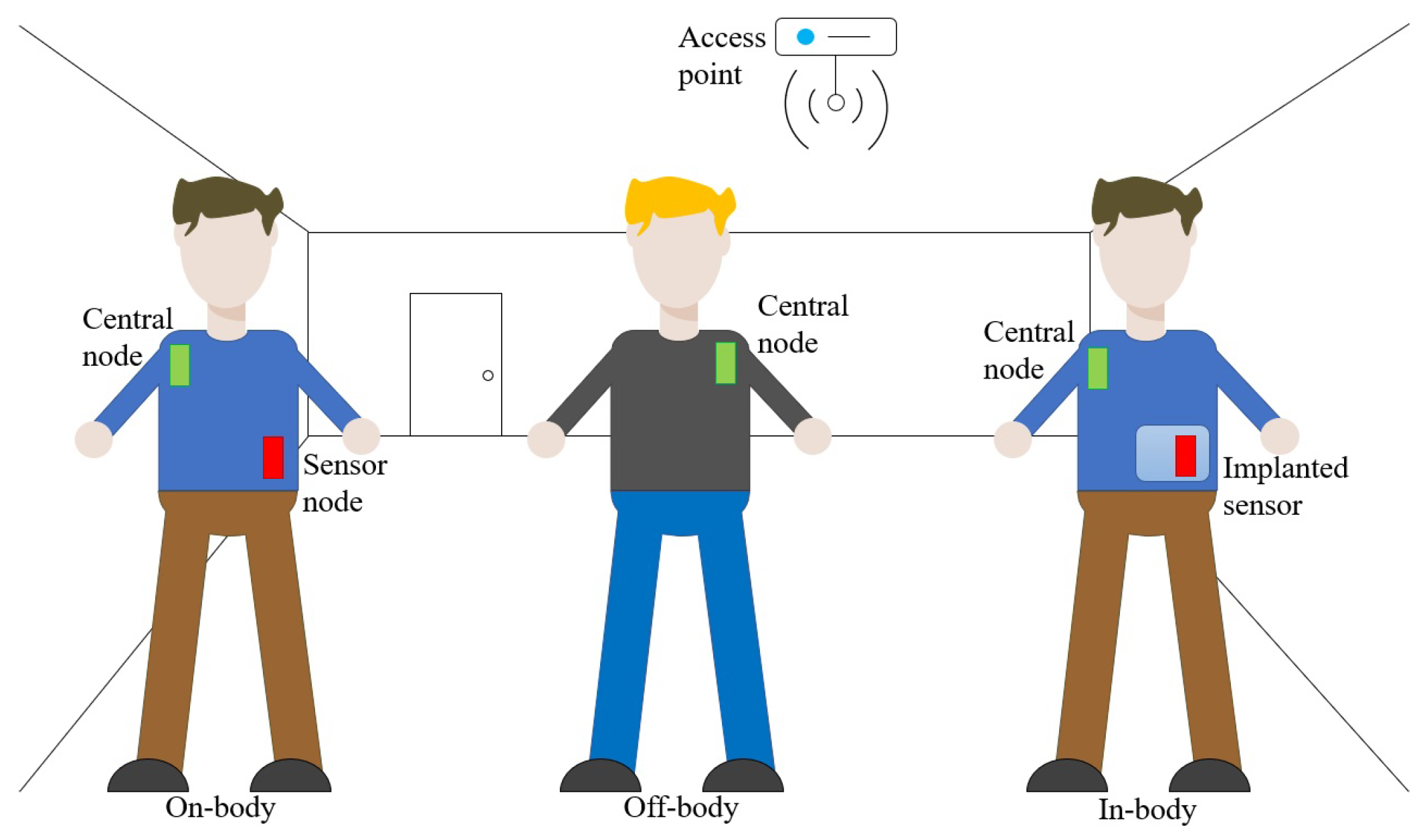
:1. Introduction
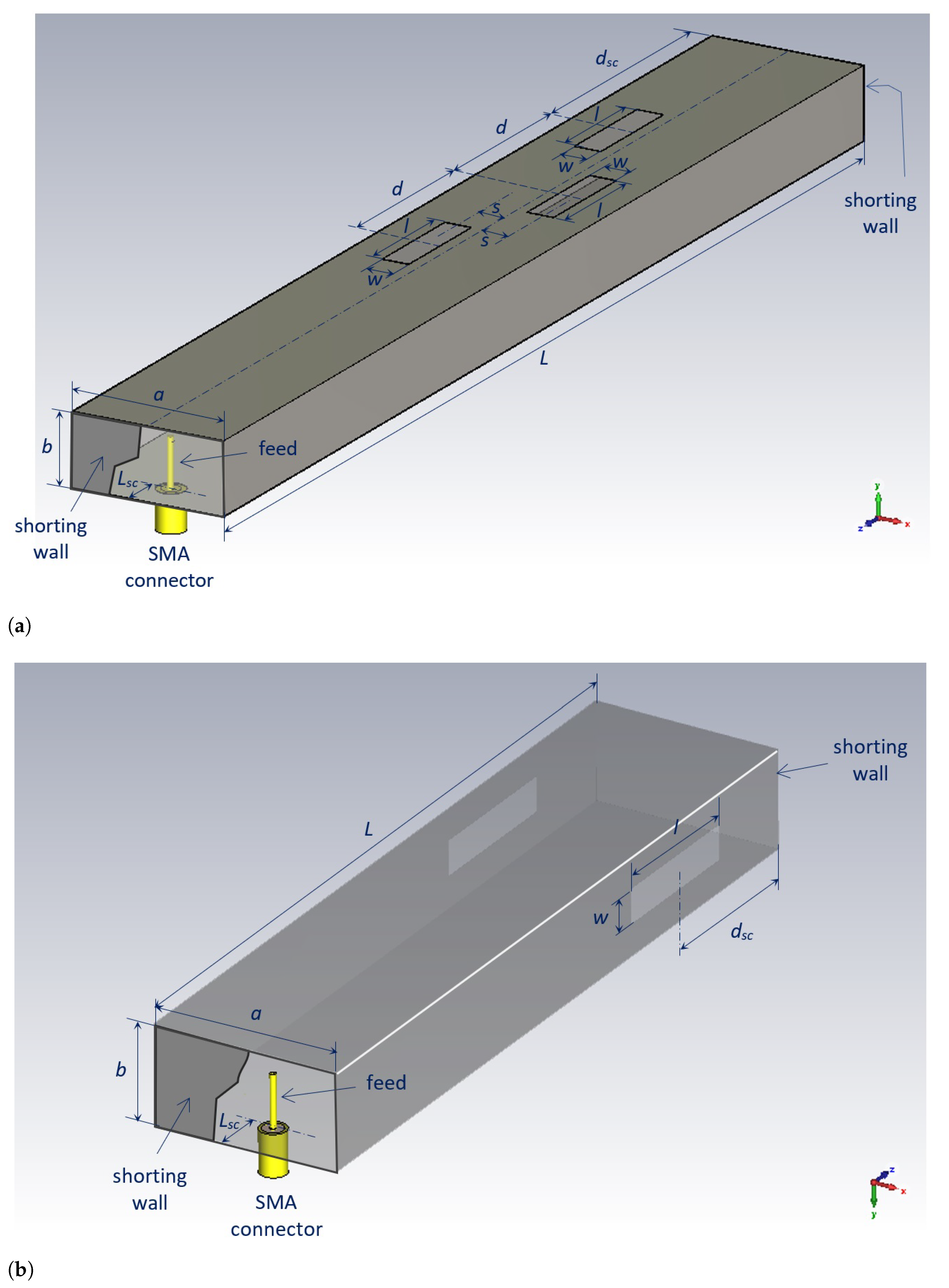
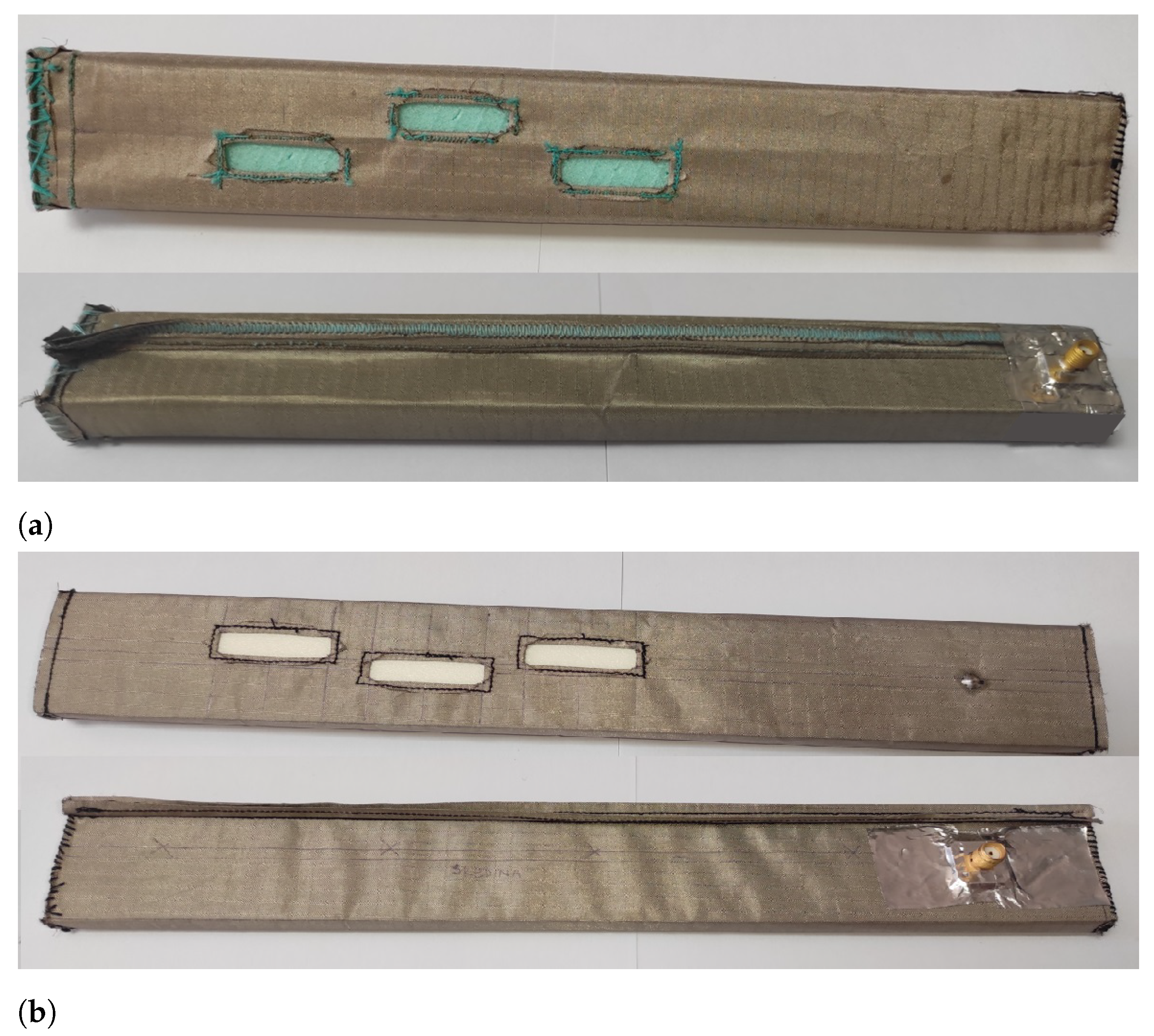
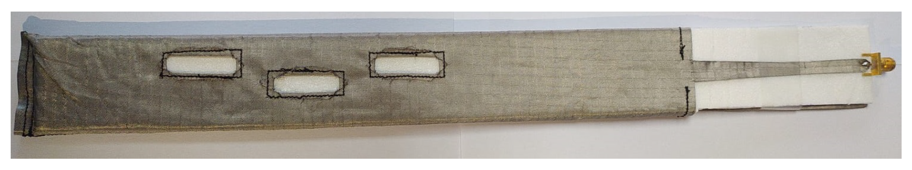
2. Realization of Textile Slotted Waveguide Antenna
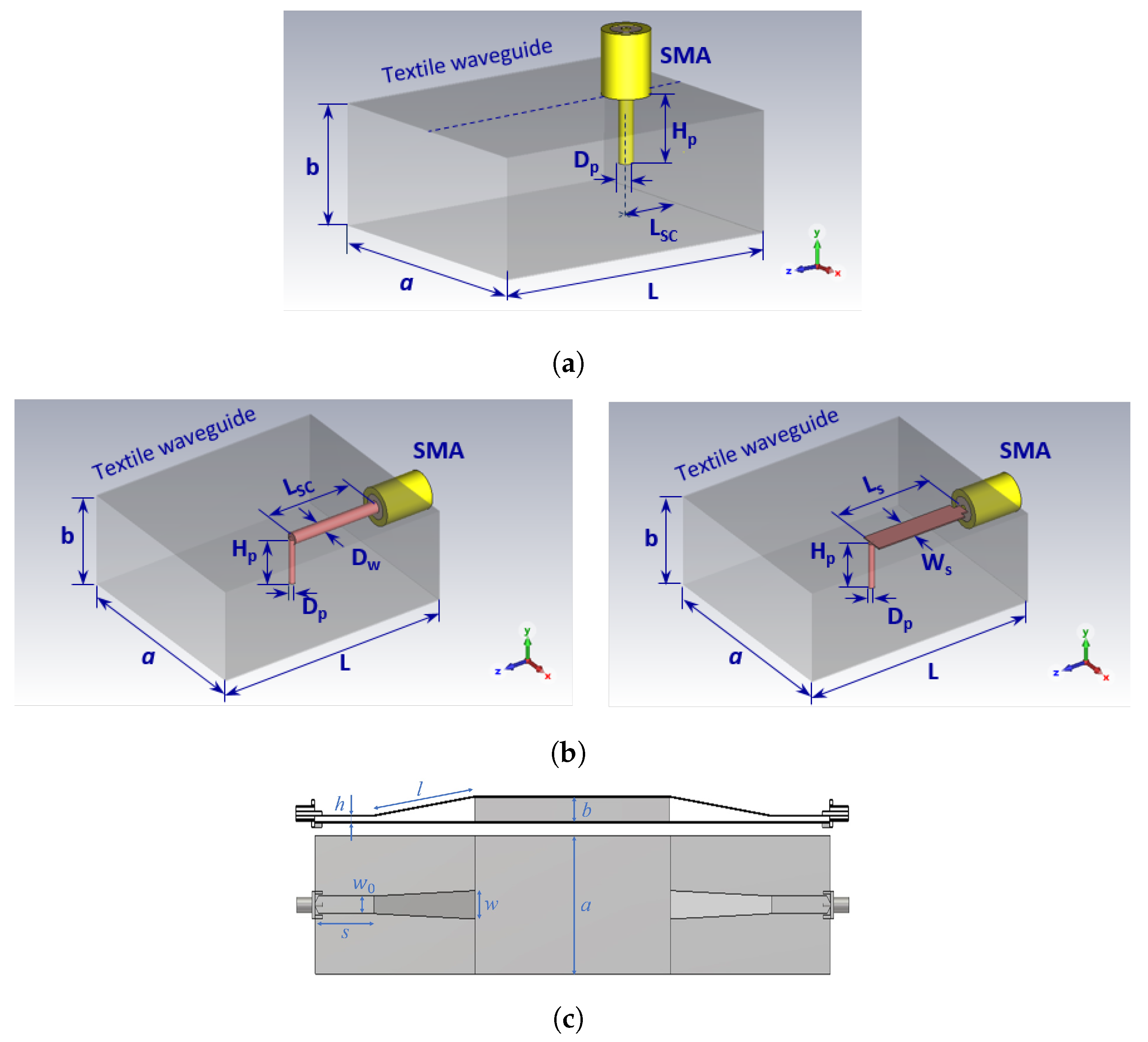
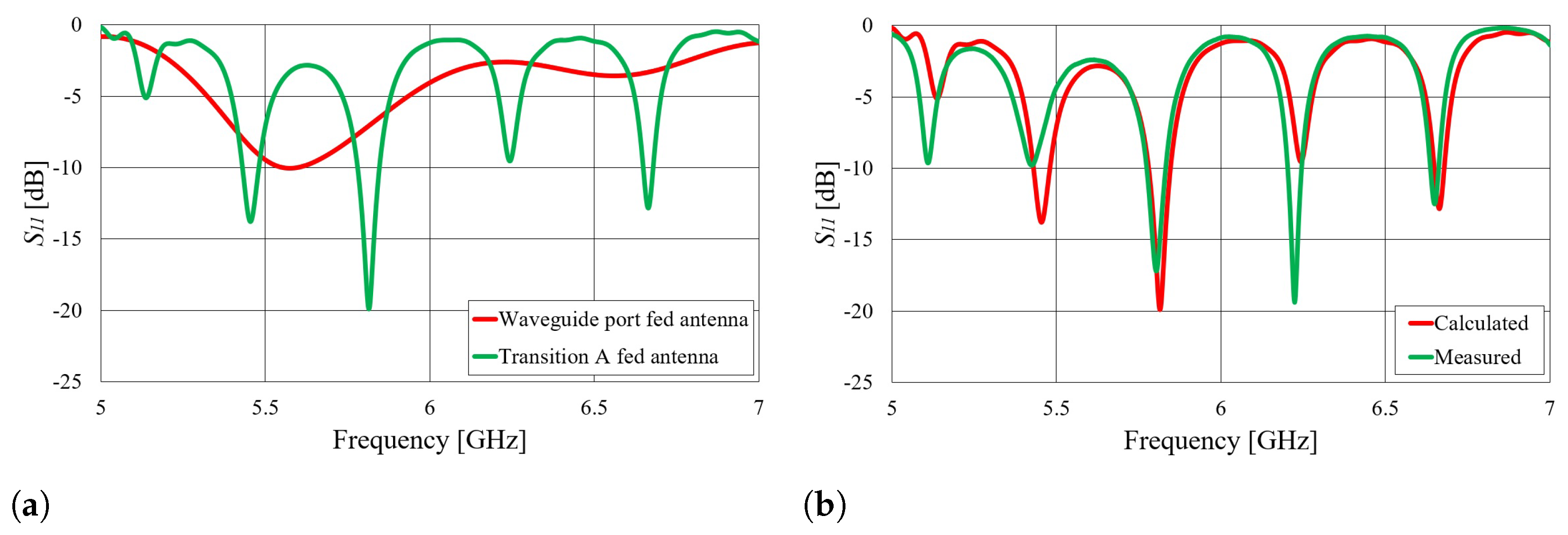
3. Feeding Possibilities
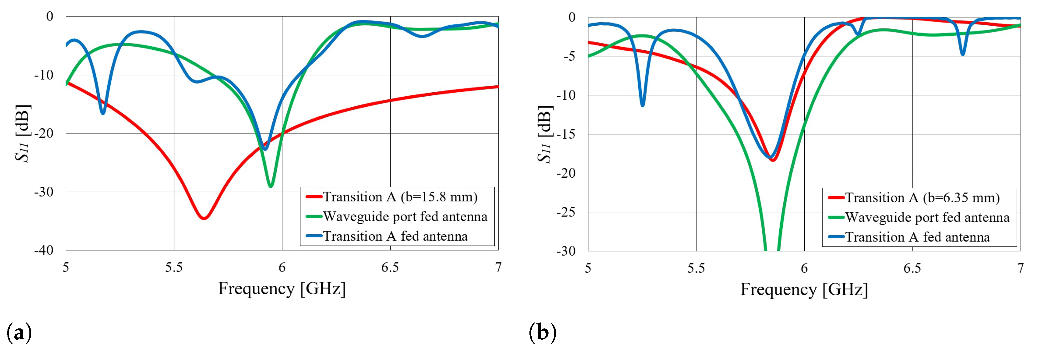
- Transition A: Top- or bottom-mounted coax-to-waveguide transition;
- Transition B: Edge-mounted coax-to-waveguide transition;
- Transition C: Microstrip line-to-waveguide transition.
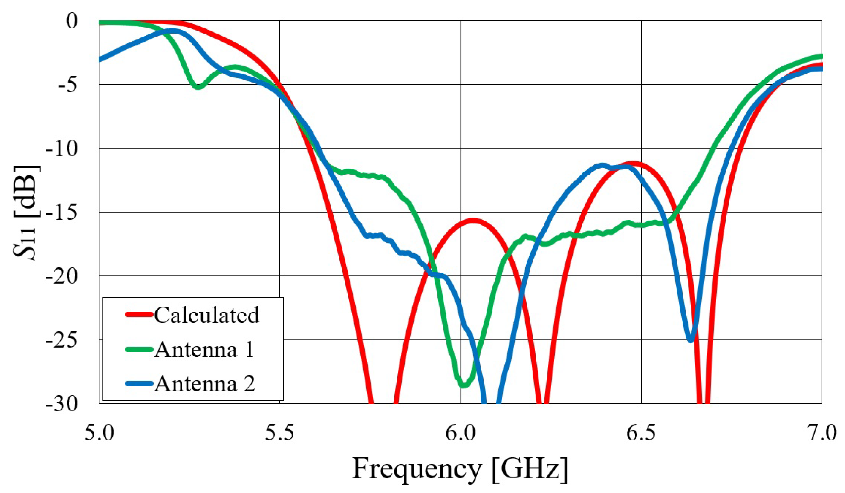
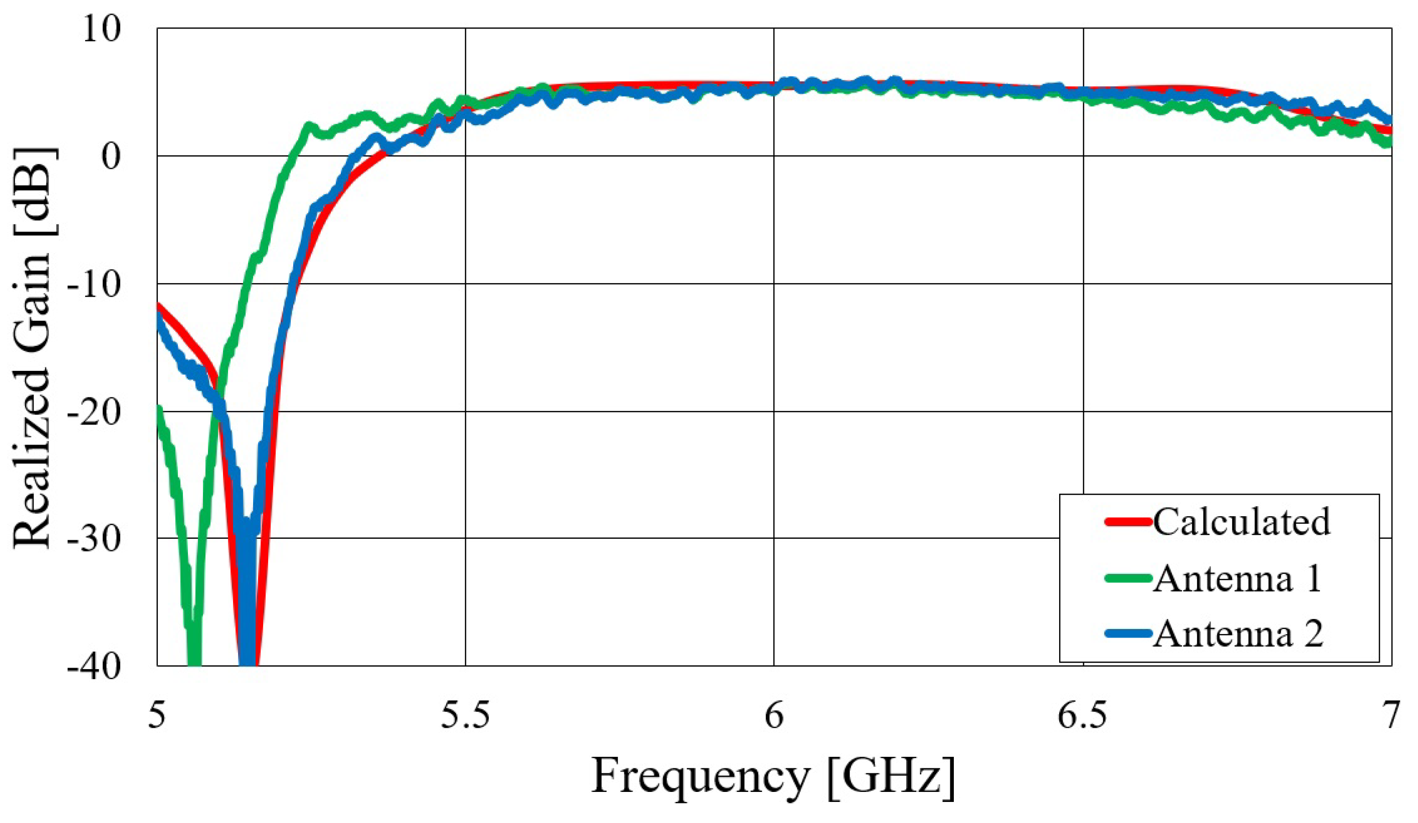
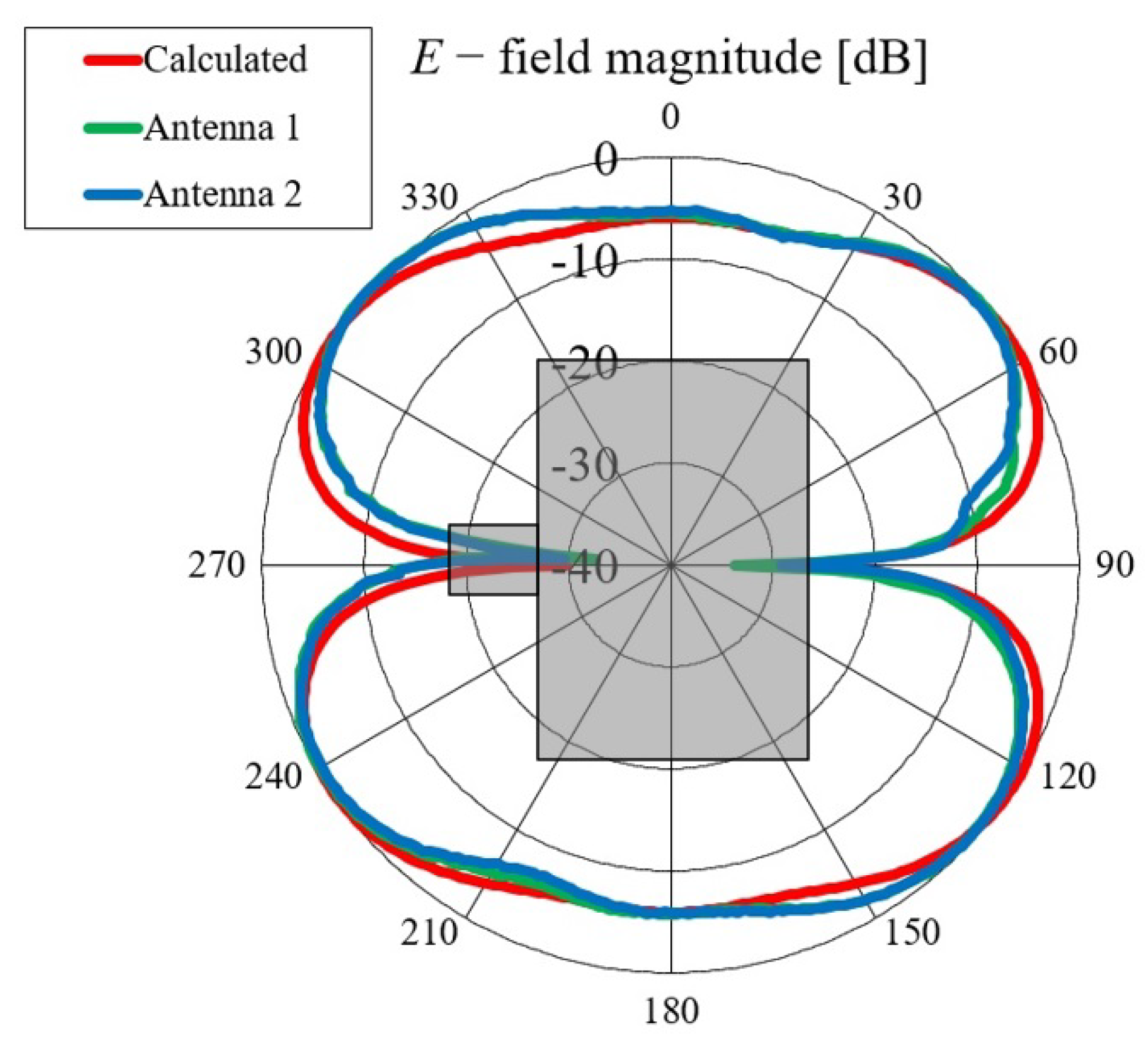
4. Experimental Characterization of Textile Slotted Waveguide Antennas
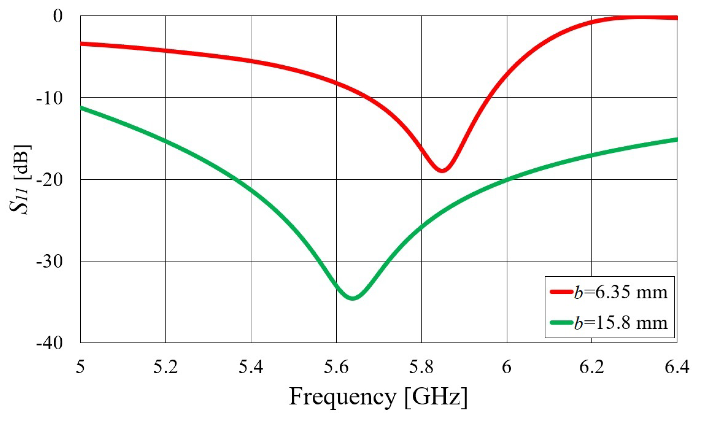
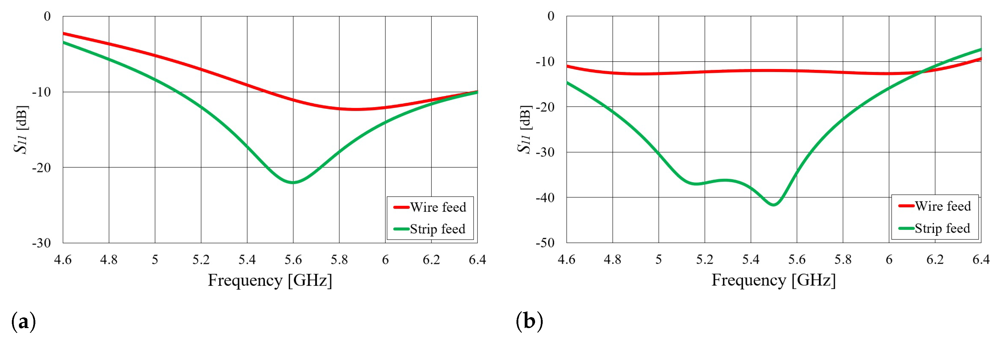
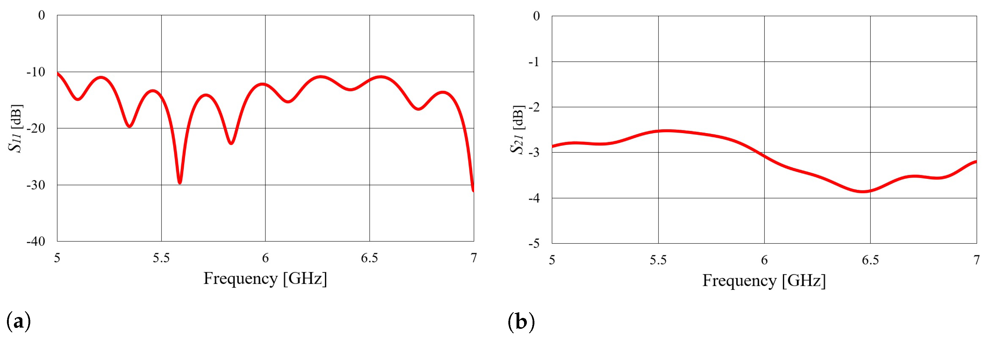
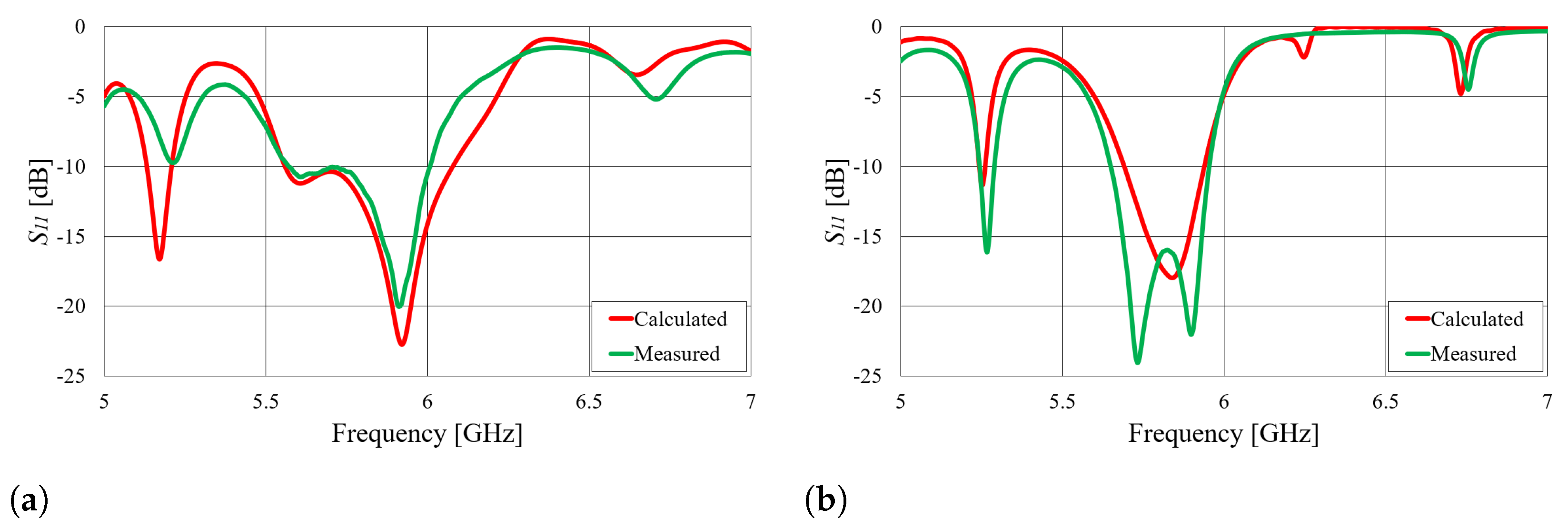
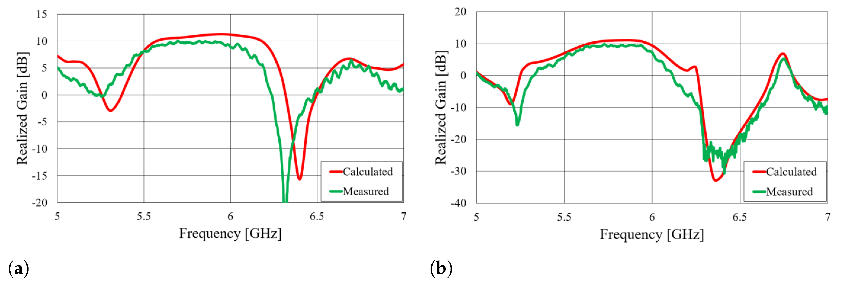
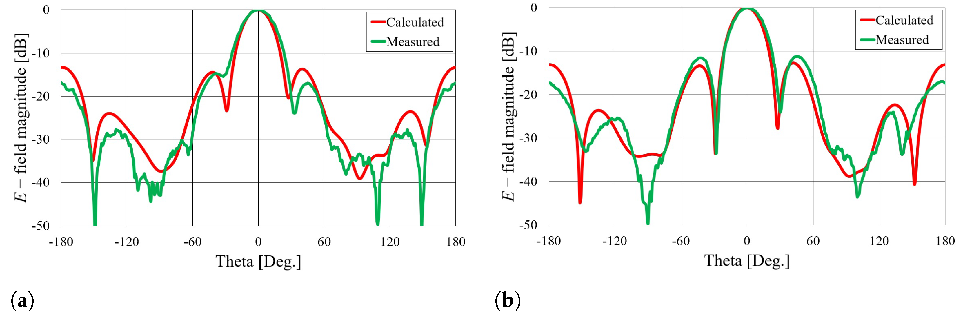
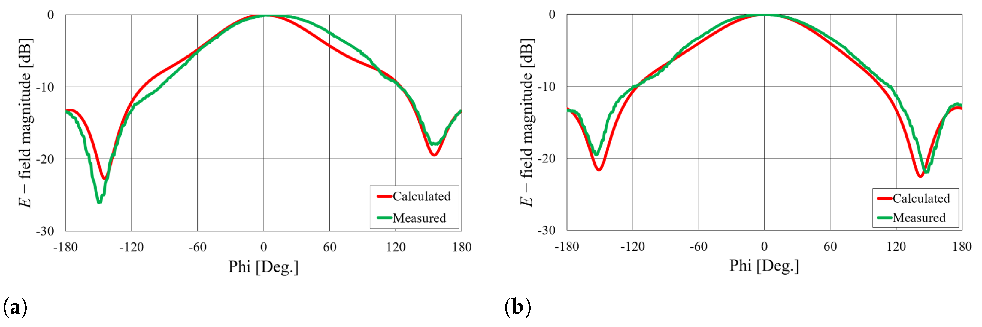
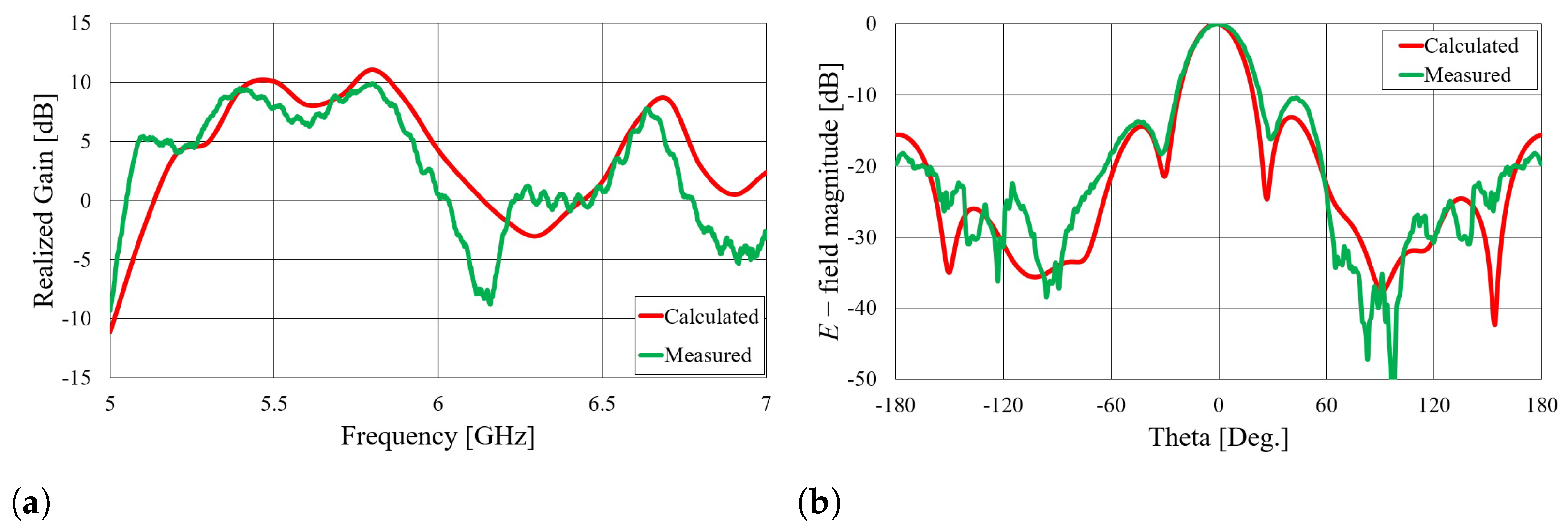
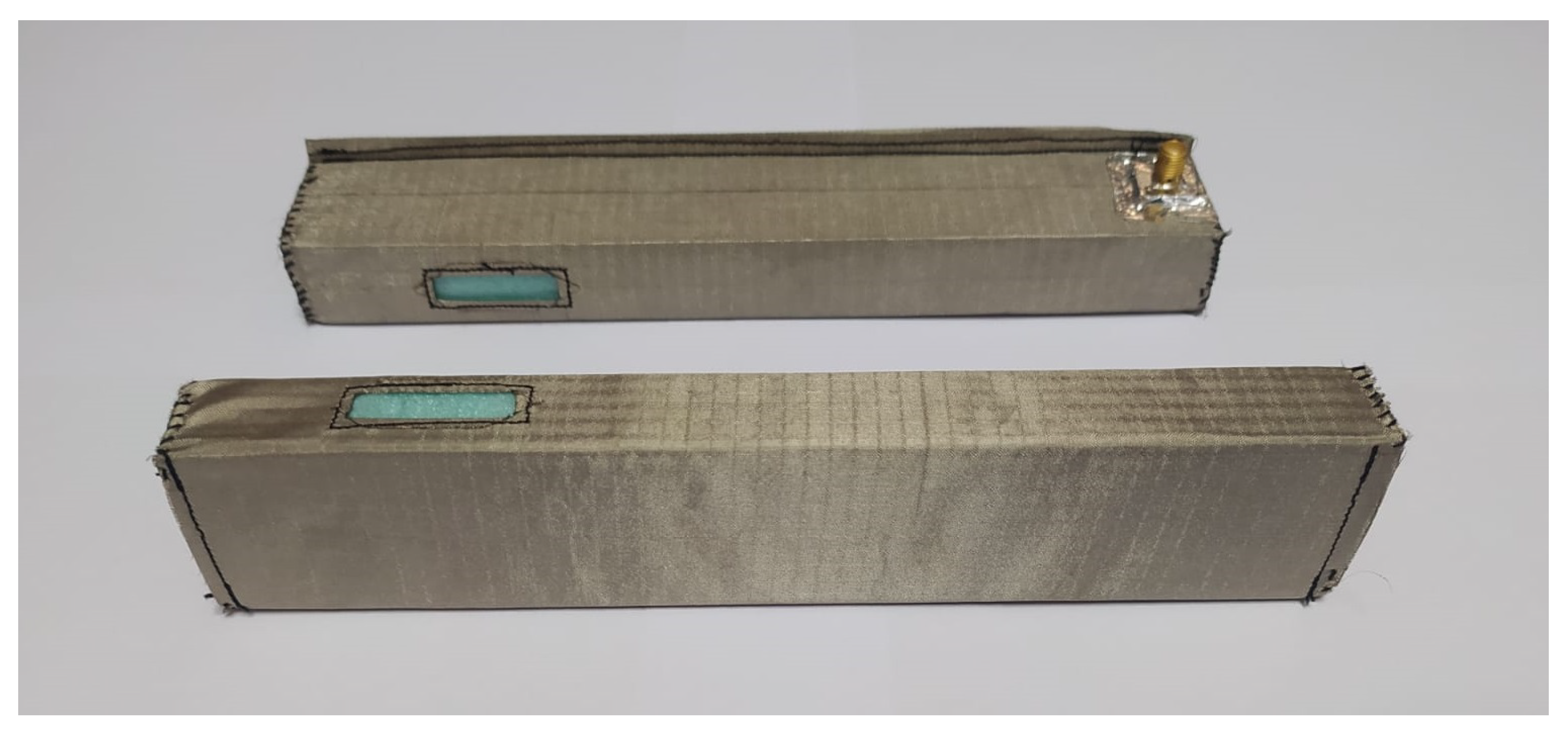
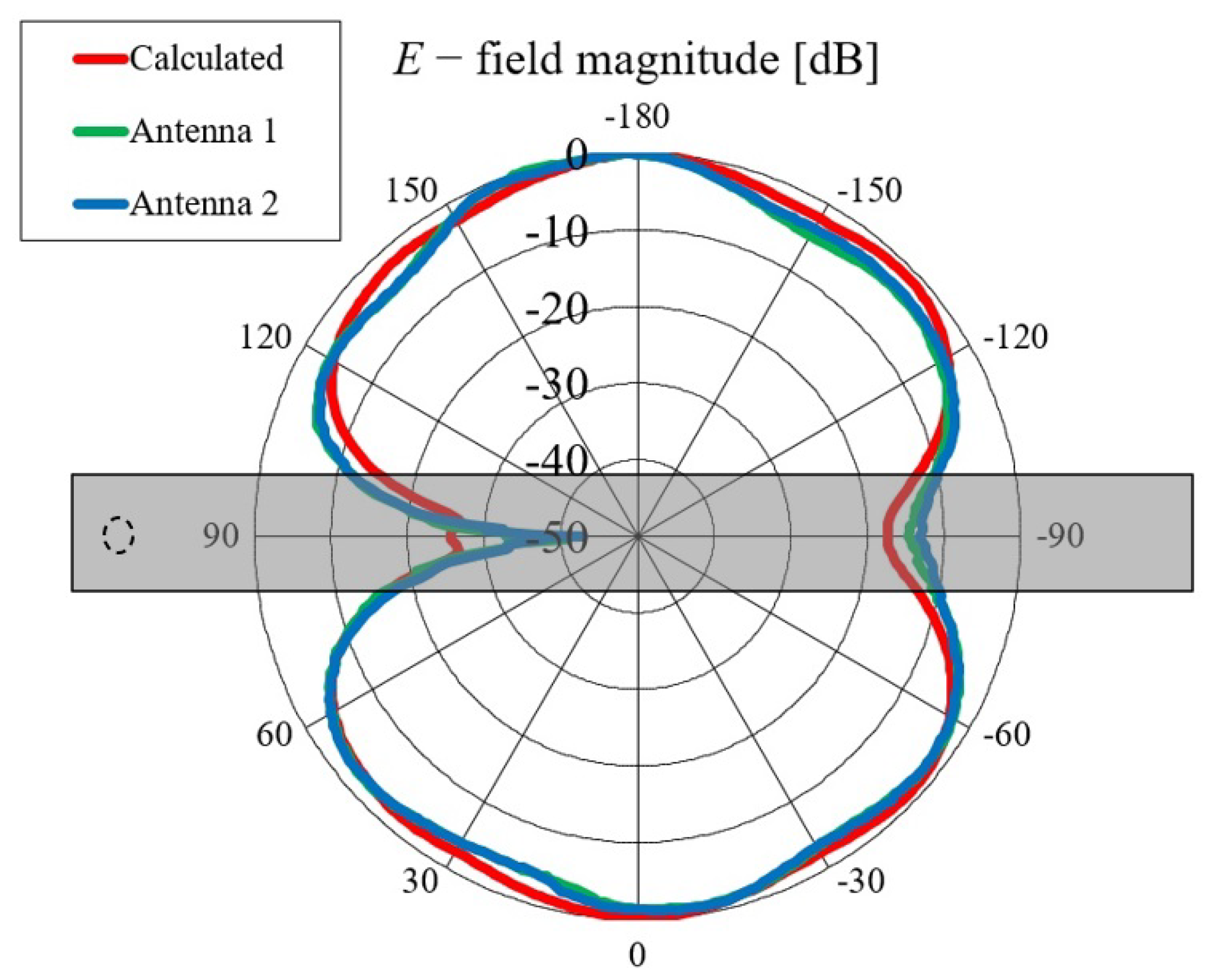
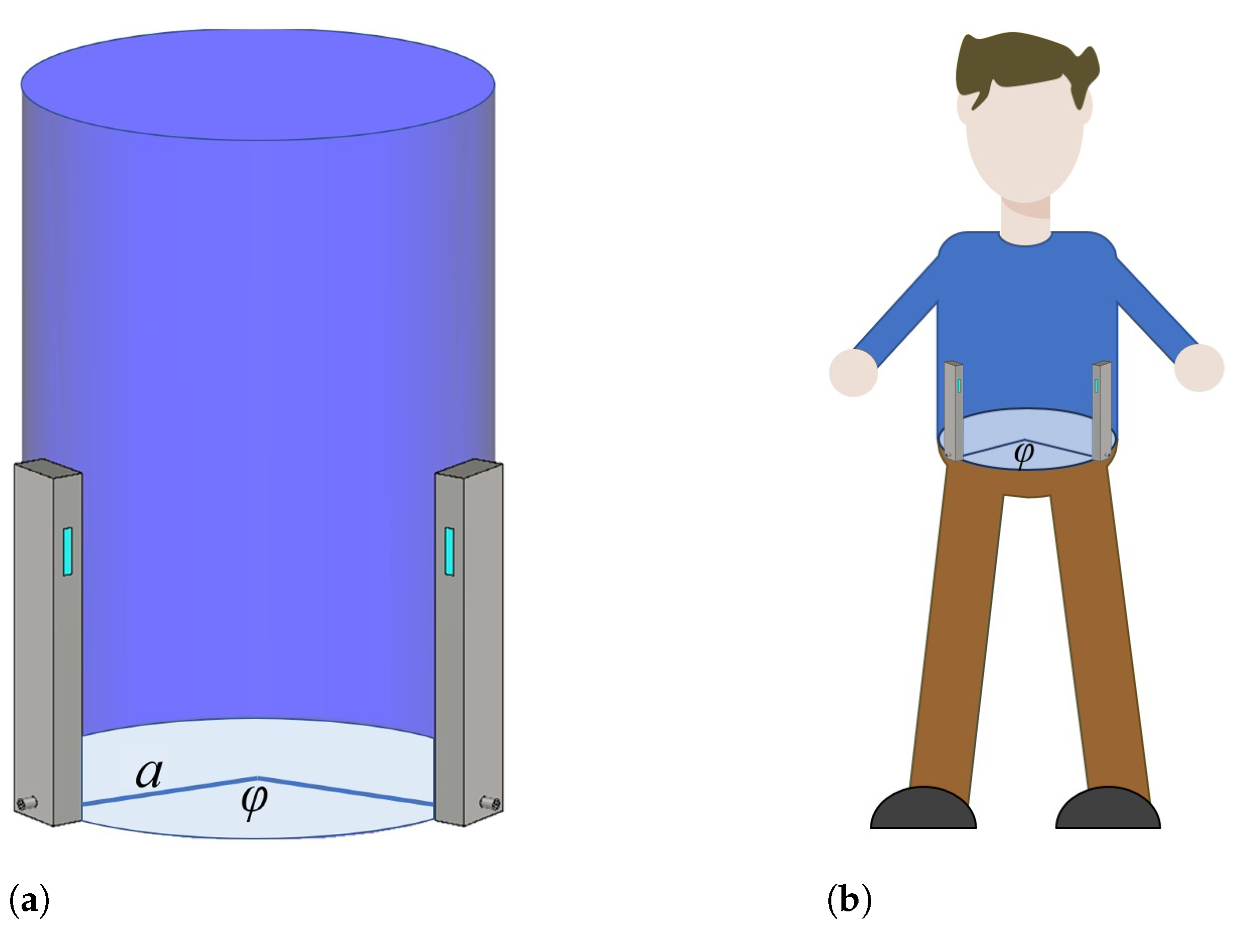
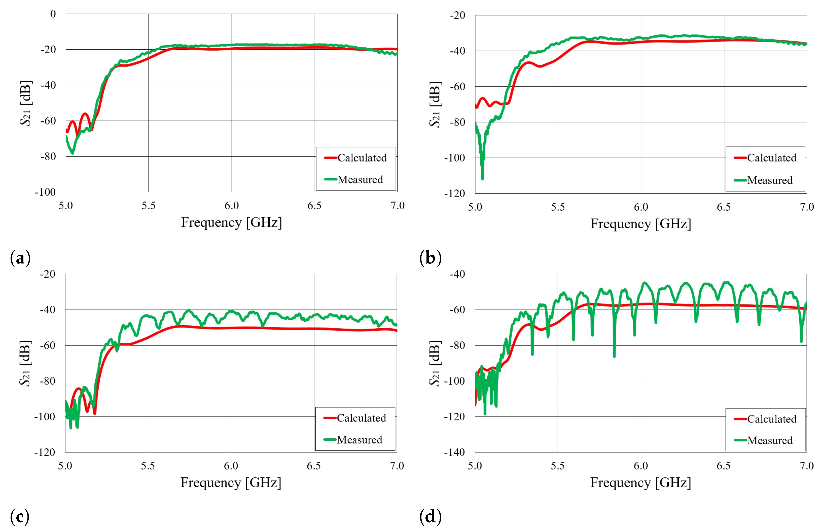
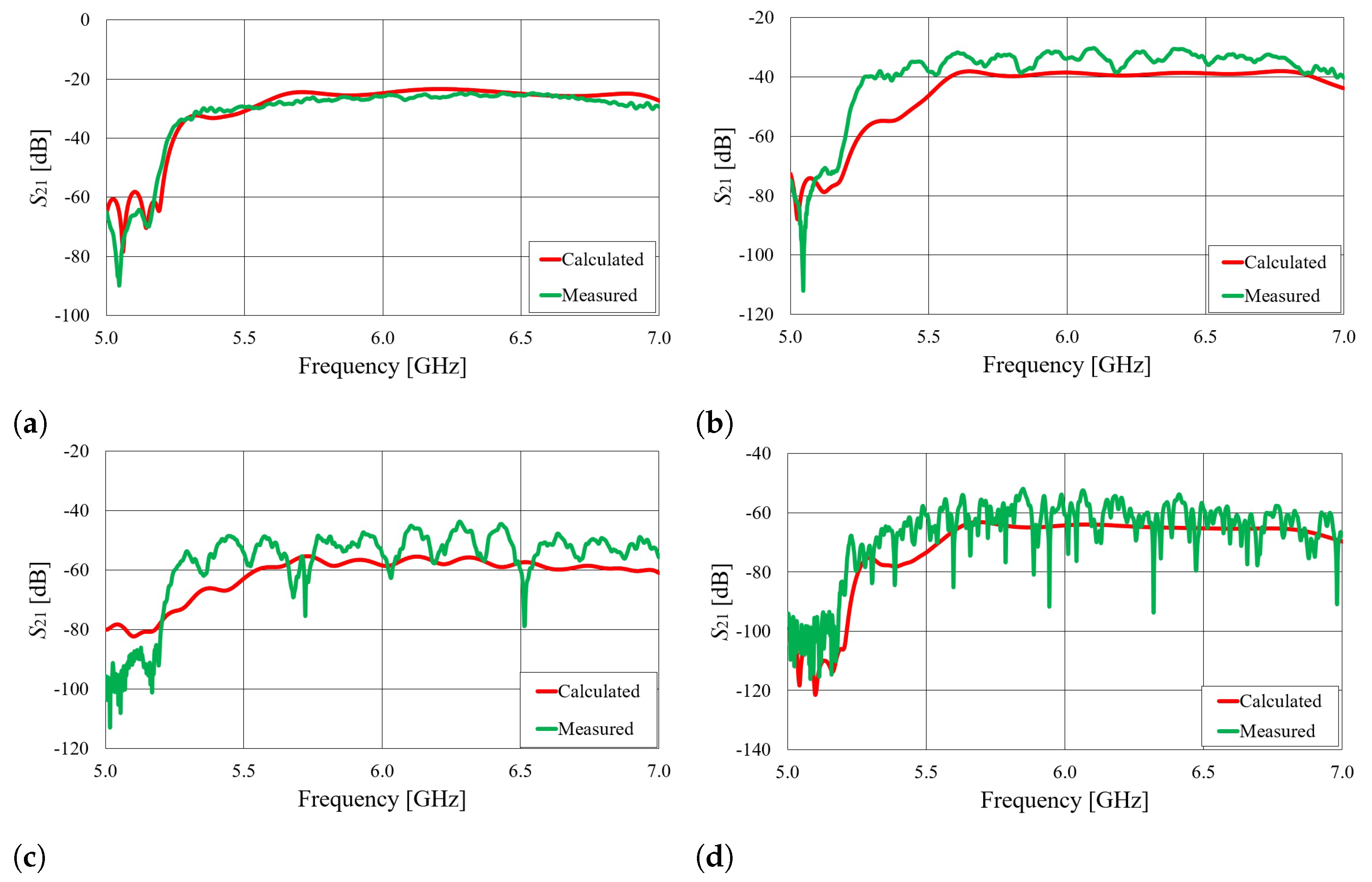
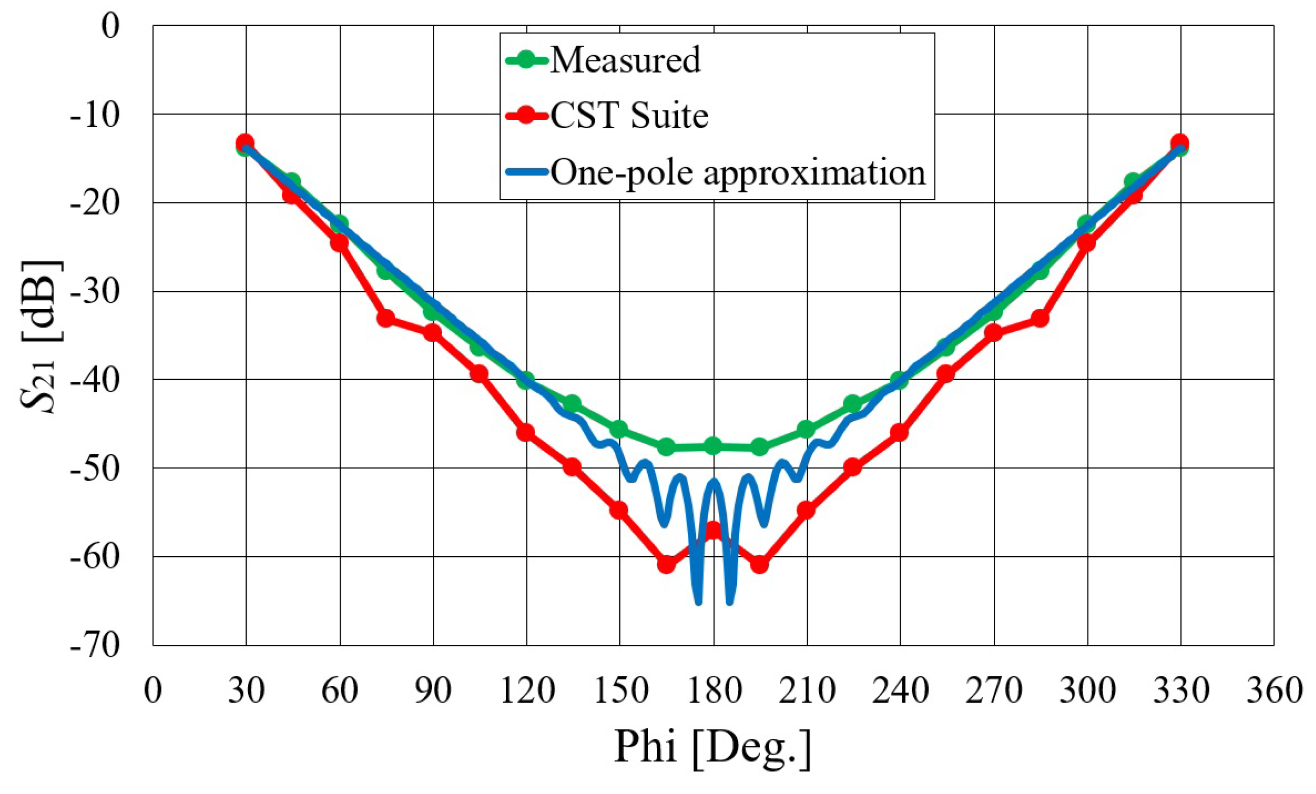
4.1. Waveguide Antennas for Off-Body Mode of Operation
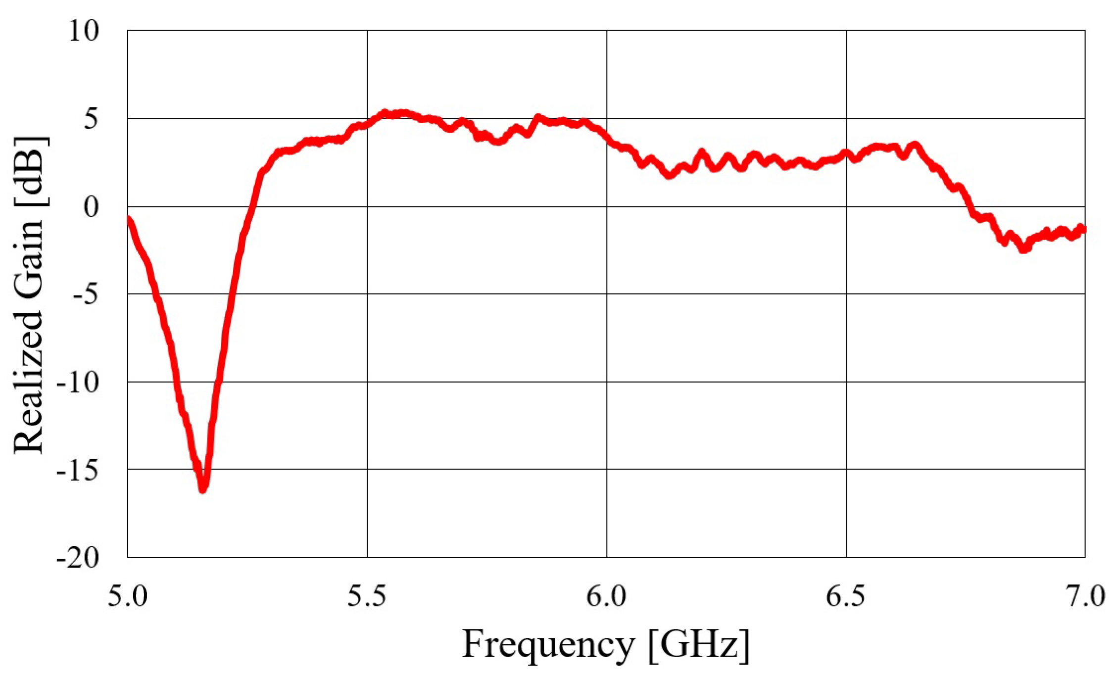
4.2. Waveguide Antennas for On-Body Mode of Operation
5. Conclusions
Author Contributions
Funding
Informed Consent Statement
Conflicts of Interest
References
- Jara, A.J. Wearable Internet: Powering Personal Devices with the Internet of Things Capabilities. In Proceedings of the 2014 International Conference on Identification, Information and Knowledge in the Internet of Things, Beijing, China, 17–18 October 2014. [Google Scholar]
- Paracha, K.N.; Rahim, S.K.A.; Soh, P.J.; Khalily, M. Wearable Antennas: A Review of Materials, Structures, and Innovative Features for Autonomous Communication and Sensing. IEEE Access 2019, 7, 56694–56712. [Google Scholar] [CrossRef]
- Whittow, W. (Ed.) Bioelectromagnetics in Healthcare: Advanced Sensing and Communication Applications; The Institution of Engineering and Technology (IET): London, UK, 2022. [Google Scholar]
- Hall, P.S.; Hao, Y. (Eds.) Antennas and Propagation for Body-Centric Wireless Communications; Artech House: Norwood, MA, USA, 2012. [Google Scholar]
- Babic, J.; Bilic, M.; Kovac, I. Safety Vest System for Human-Robot Collaboration. In Proceedings of the 2022 International Convention on Information, Communication and Electronic Technology (MIPRO), Opatija, Croatia, 23–27 May 2022. [Google Scholar]
- Corchia, L.; Monti, G.; Tarricone, L. Wearable antennas: Nontextile versus fully textile solutions. IEEE Antennas Propag. Mag. 2019, 61, 71–83. [Google Scholar] [CrossRef]
- Roh, J.S.; Chi, Y.S.; Kang, T.J. Wearable textile antennas. Int. J. Fash. Des. Technol. Educ. 2010, 3, 135–153. [Google Scholar] [CrossRef]
- Mahmood, S.N.; Ishak, A.J.; Saeidi, T.; Alsariera, H.; Alani, S.; Ismail, A.; Soh, A. Recent Advances in Wearable Antenna Technologies: A Review. Prog. Electromagn. Res. B 2020, 89, 1–27. [Google Scholar] [CrossRef]
- Ivsic, B.; Bonefacic, D.; Bartolic, J. Considerations on Embroidered Textile Antennas for Wearable Applications. IEEE Antennas Wirel. Propag. Lett. 2012, 11, 799–802. [Google Scholar] [CrossRef]
- Nepa, P.; Rogier, H. Wearable Antennas for Off-Body Radio Links at VHF and UHF Bands: Challenges, the state of the art, and future trends below 1 GHz. IEEE Antennas Propag. Mag. 2015, 57, 30–52. [Google Scholar] [CrossRef]
- Hirokawa, J.; Zhang, M. Waveguide Slot Array Antennas. In Handbook of Antenna Technologies; Chen, Z., Ed.; Springer: Singapore, 2016; pp. 1389–1413. [Google Scholar]
- Sanz-Izquierdo, G.B.; Wu, L.; Batchelor, J.C.; Young, P.R. Textile integrated waveguide slot antenna. In Proceedings of the 2010 IEEE Antennas and Propagation Society International Symposium, Toronto, ON, Canada, 11–17 July 2010. [Google Scholar]
- Lemey, H.S.; Rogier, H. Substrate integrated waveguide textile antennas as energy harvesting platforms. In Proceedings of the 2015 International Workshop on Antenna Technology (iWAT), Seoul, Republic of Korea, 4–6 March 2015. [Google Scholar]
- Alonso, L.; Ver Hoeye, S.; Fernández, M.; Vazquez, C.; Camblor, R.; Hotopan, G.; Hadarig, A.; Las-Heras, F. Millimetre wave textile integrated waveguide beamforming antenna for radar applications. In Proceedings of the Global Symposium on Millimeter-Waves, Montreal, QC, Canada, 25–27 May 2015. [Google Scholar]
- Lajevardi, M.E.; Kamyab, M. Ultraminiaturized metamaterial-inspired SIW textile antenna for off-body applications. IEEE Antennas Wirel. Propag. Lett. 2017, 16, 3155–3158. [Google Scholar] [CrossRef]
- Kokolia, M.; Raida, Z. AMC-Based Textile-Integrated Antenna. In Proceedings of the 23rd International Microwave and Radar Conference (MIKON), Warsaw, Poland, 5–7 October 2020. [Google Scholar]
- Kokolia, D.; Raida, Z. Textile-integrated microwave components based on artificial magnetic conductor. Int. J. Numer. Model. 2021, 34, e2864. [Google Scholar] [CrossRef]
- Mikulic, D.; Sopp, E.; Bonefacic, D.; Sipus, Z. Textile slotted waveguide antennas for body-centric applications. Sensors 2022, 22, 1046. [Google Scholar] [CrossRef]
- Mikulic, D.; Sopp, E.; Bonefacic, D.; Sipus, Z. Wearable Slotted Waveguide Textile Antenna. In Proceedings of the 16th European Conference on Antennas and Propagation (EuCAP), Madrid, Spain, 27 March–1 April 2022; pp. 1–5. [Google Scholar]
- Mikulic, D.; Sopp, E.; Bonefacic, D.; Sipus, Z. Textile Slotted Waveguide Antenna: Feeding Considerations. In Proceedings of the 17th European Conference on Antennas and Propagation (EuCAP), Florence, Italy, 26–31 March 2023; pp. 1–5. [Google Scholar]
- Shieldex. Available online: https://www.shieldex.de/en/products/shieldex-nora-dell/ (accessed on 15 June 2023).
- Cuming Microwave C-FOAM PF-2 and PF-4. Available online: https://www.cumingmicrowave.com/dielectric-materials-application/c-foam-pf-2-and-pf-4.html (accessed on 15 June 2023).
- CST Studio Suite. Dassault Systèmes. Available online: https://www.3ds.com/products-services/simulia/products/cst-studio-suite/ (accessed on 24 May 2023).
- Kumar, H.; Jadhav, R.; Ranade, S. A Review on Substrate Integrated Waveguide and its Microstrip Interconnect. J. Electron. Commun. Eng. 2012, 3, 36–40. [Google Scholar] [CrossRef]
- Deslandes, D. Design equations for tapered microstrip-to-Substrate Integrated Waveguide transitions. In Proceedings of the IEEE MTT-S International Microwave Symposium Digest, Anaheim, CA, USA, 23–28 May 2010; pp. 704–707. [Google Scholar]
- Bonefacic, D. Conductive Adhesives at Microwave Frequencies: Silver-Filled vs. Graphite-Filled. In Proceedings of the 17th European Conference on Antennas and Propagation (EuCAP), Florence, Italy, 26–31 March 2023; pp. 1–4. [Google Scholar]
- Hollandshielding. Available online: https://hollandshielding.com/Electrically-conductive-adhesive-shieldokit (accessed on 15 June 2023).
- Song, H.; Wei, B.; Yu, Q.; Xiao, X.; Kikkawa, T. WiEps: Measurement of Dielectric Property With Commodity WiFi Device—An Application to Ethanol/Water Mixture. IEEE Internet Things J. 2020, 7, 11667–11677. [Google Scholar] [CrossRef]
- Federal Communications Commission (FCC). Evaluating Compliance with FCC Guidelines for Human Exposure to Radiofrequency Electromagnetic Fields, 97-01 ed.; Supplement C, OET Bulletin; FCC Std.: Washington, DC, USA, 2001; Volume 65, p. 35. [Google Scholar]
- Wait, J.R. Electromagnetic Radiation From Cylindrical Structures; Pergamon Press: Oxford, UK, 1959. [Google Scholar]
- Alves, T.; Poussot, B.; Laheurte, L.-M. Analytical Propagation Modeling of BAN Channels Based on the Creeping-Wave Theory. IEEE Trans. Antennas Propag. 2011, 59, 1269–1274. [Google Scholar] [CrossRef]
- Ivsic, B.; Bonefacic, D.; Sipus, Z.; Bartolic, J. An Insight into Creeping Electromagnetic Waves around the Human Body. Wirel. Commun. Mob. Comput. 2017, 2017, 2510196. [Google Scholar] [CrossRef]
- Paknys, R. Evaluation of Hankel Functions with Complex Argument and Complex Order. IEEE Trans. Antennas Propag. 1992, 40, 569–578. [Google Scholar] [CrossRef]
- Galdi, V.; Pinto, I.M. A simple algorithm for accurate location of leaky-wave poles for grounded inhomogeneous dielectric slabs. Microwave Opt. Technol. Lett. 2000, 24, 135–140. [Google Scholar] [CrossRef]


| Antenna with Rigid Mold | Antenna with Bendable Mold | |
|---|---|---|
| Waveguide width (a) | mm | mm |
| Waveguide height (b) | mm | mm |
| Mold permittivity () |
| Antenna with Rigid Mold | Antenna with Bendable Mold | |
|---|---|---|
| Pin length () | mm | mm |
| Distance from | ||
| short-circuit wall () | mm | mm |
| Antenna with Rigid Mold | Antenna with Bendable Mold | |||
|---|---|---|---|---|
| Pin/strip | ||||
| length | mm | mm | mm | mm |
| Pin/strip | ||||
| diameter/width | mm | mm | mm | mm |
| Vertical | ||||
| wire length | mm | mm | mm | mm |
| Vertical | ||||
| wire diameter | mm | mm | mm | mm |
| 50 microstrip line width () | mm |
| Taper width (w) | mm |
| 50 microstrip line length (s) | 30 mm |
| Taper length (l) | 52 mm |
| Waveguide width (a) | mm |
| Waveguide height (b) | mm |
| 50 microstrip line height (h) | mm |
| Antenna with Rigid Mold | Antenna with Bendable Mold | |
|---|---|---|
| Slot length (l) | mm | mm |
| Slot width (w) | mm | mm |
| Slot offset (s) | mm | mm |
| Slot spacing (d) | mm | mm |
| Spacing from SC () | mm | mm |
Disclaimer/Publisher’s Note: The statements, opinions and data contained in all publications are solely those of the individual author(s) and contributor(s) and not of MDPI and/or the editor(s). MDPI and/or the editor(s) disclaim responsibility for any injury to people or property resulting from any ideas, methods, instructions or products referred to in the content. |
© 2023 by the authors. Licensee MDPI, Basel, Switzerland. This article is an open access article distributed under the terms and conditions of the Creative Commons Attribution (CC BY) license (https://creativecommons.org/licenses/by/4.0/).
Share and Cite
Mikulić, D.; Šopp, E.; Bonefačić, D.; Bartolić, J.; Šipuš, Z. Design and Realization of Wearable Textile Slotted Waveguide Antennas. Sensors 2023, 23, 7509. https://doi.org/10.3390/s23177509
Mikulić D, Šopp E, Bonefačić D, Bartolić J, Šipuš Z. Design and Realization of Wearable Textile Slotted Waveguide Antennas. Sensors. 2023; 23(17):7509. https://doi.org/10.3390/s23177509
Chicago/Turabian StyleMikulić, Davorin, Evita Šopp, Davor Bonefačić, Juraj Bartolić, and Zvonimir Šipuš. 2023. "Design and Realization of Wearable Textile Slotted Waveguide Antennas" Sensors 23, no. 17: 7509. https://doi.org/10.3390/s23177509