
Analysis of Return-to-Zero Error after the First Load of Load Cell
Abstract
:1. Introduction
2. Characterization and Principle Analysis of Return-to-Zero Error
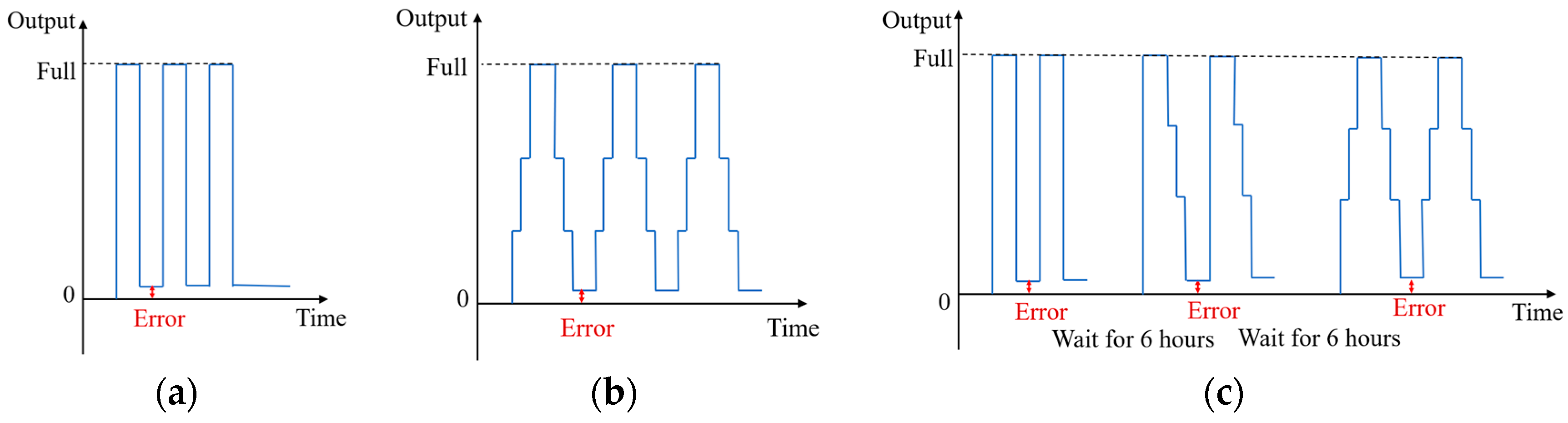
2.1. Zero-Return Characteristics of Load Cells
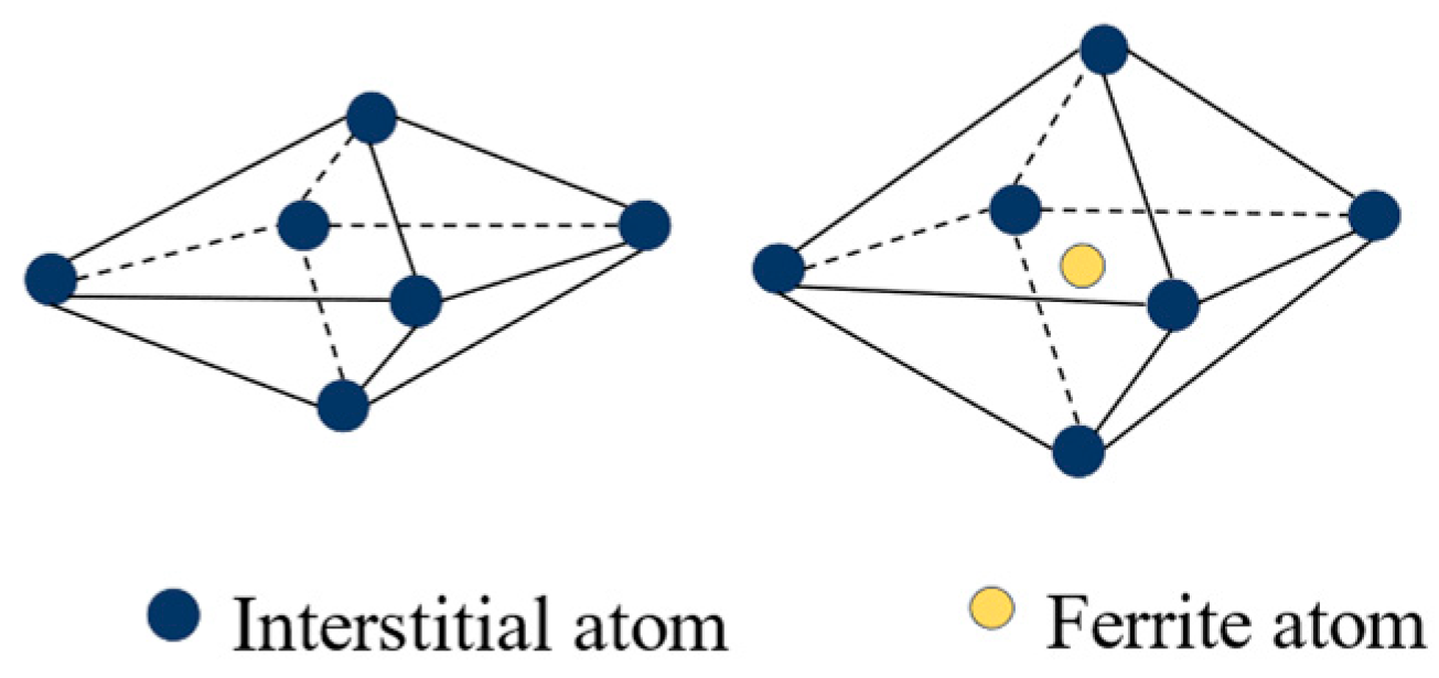
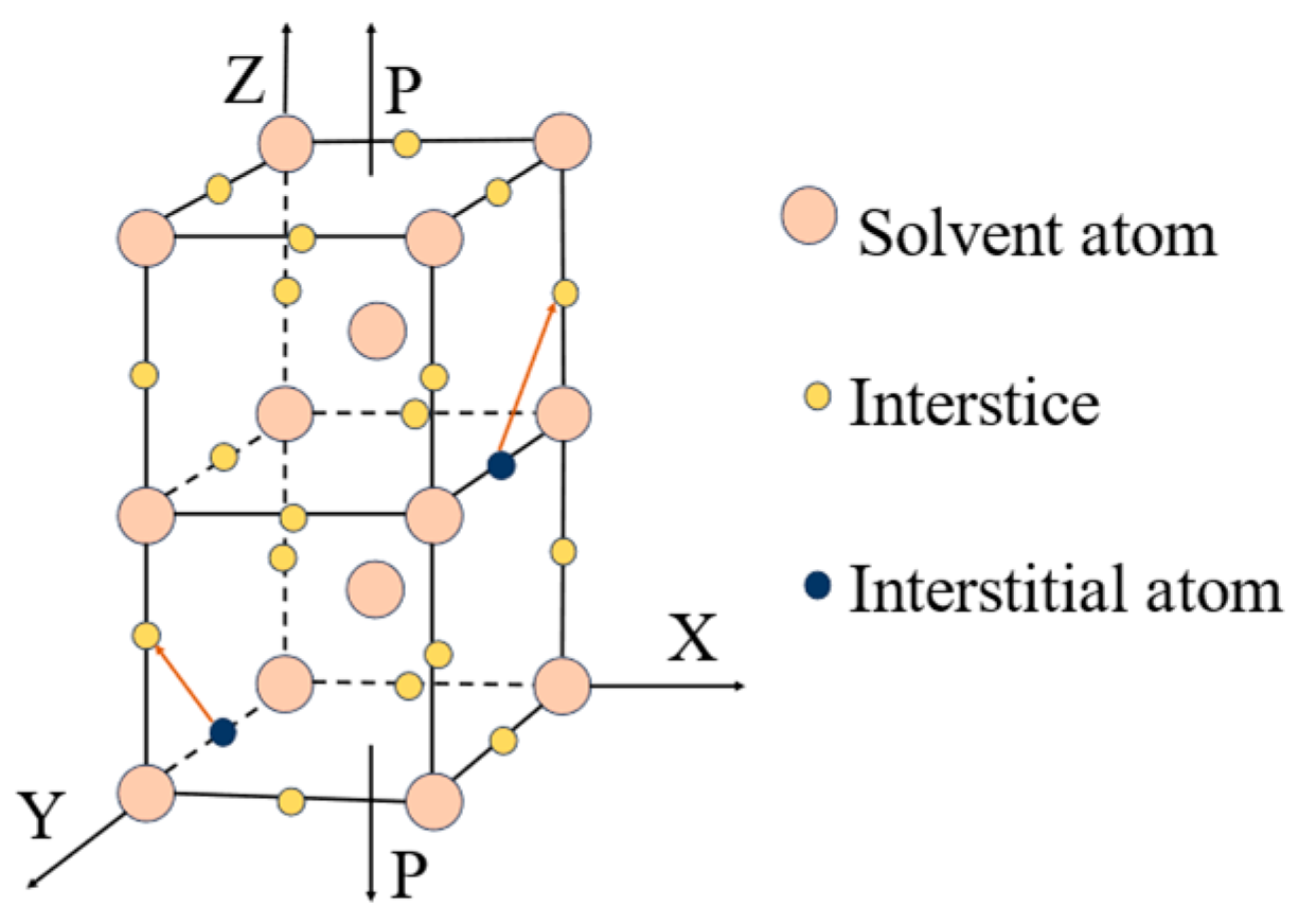
2.2. Factors Generating Return-to-Zero Error after First Loading
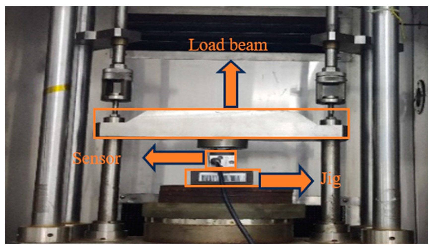
2.3. Design of the Experiment
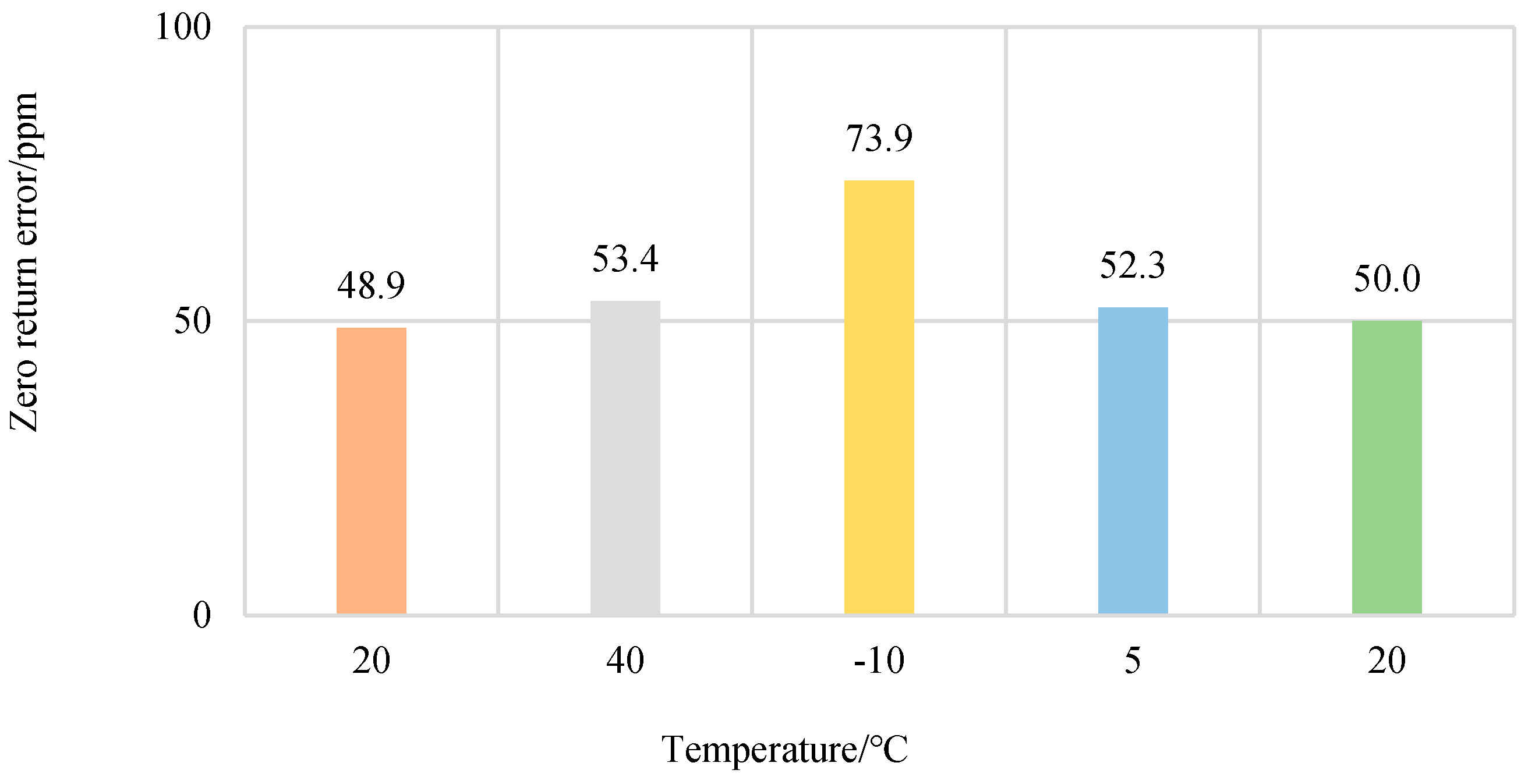
2.3.1. Temperature Experiments
- (1)
- Set the temperature of the chamber to 20 °C. The chamber temperature was stabilized and maintained for 24 h. The sensor was loaded and unloaded at full scale and each zero point was recorded.
- (2)
- The temperature of the chamber was increased from 20 °C to 40 °C. The chamber temperature was stabilized and maintained for 24 h. The sensor was loaded and unloaded at full scale and each zero point was recorded.
- (3)
- The temperature of the chamber was decreased from 40 °C to −10 °C. The chamber temperature was stabilized and maintained for 24 h. The sensor was loaded and unloaded at full scale and each zero point was recorded.
- (4)
- The temperature of the chamber was increased from −10 °C to 5 °C. The chamber temperature was stabilized and maintained for 24 h. The sensor was loaded and unloaded at full scale and each zero point was recorded.
- (5)
- The temperature of the chamber was increased from 5 °C to 20 °C. The chamber temperature was stabilized and maintained for 24 h. the sensor was loaded and unloaded at full scale and each zero point was recorded.
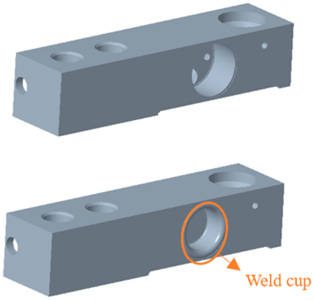
2.3.2. Experiments with and without Weld Cup
2.3.3. Experiments with Different Elastomer Materials
3. Results and Discussion
3.1. Temperature
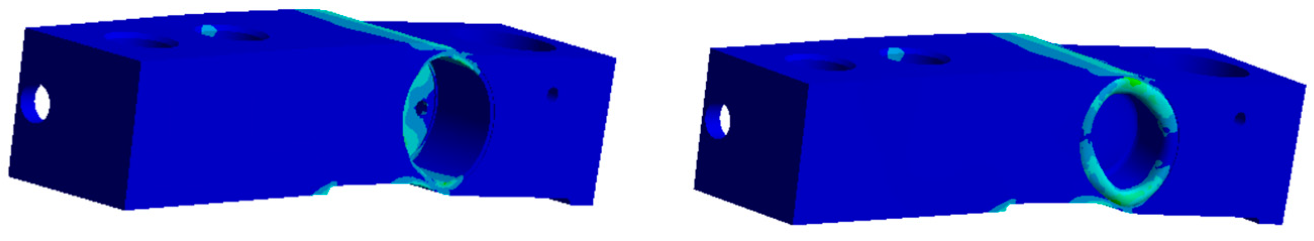
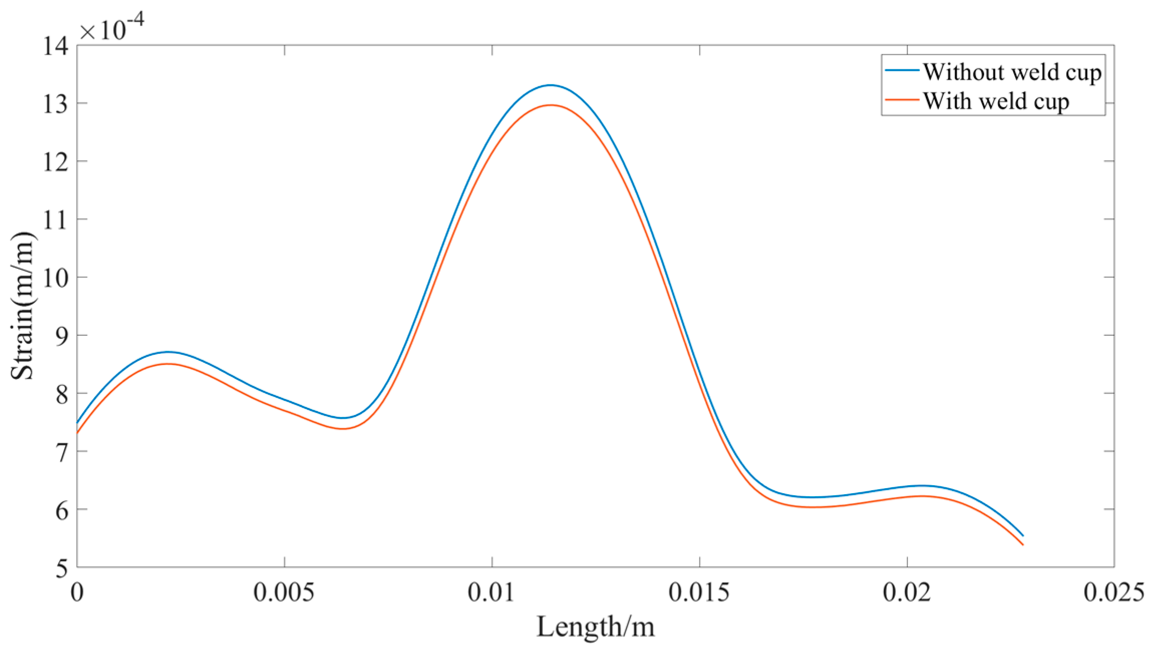
3.2. Weld Cup
3.3. Elastomer Materials
3.4. Analysis
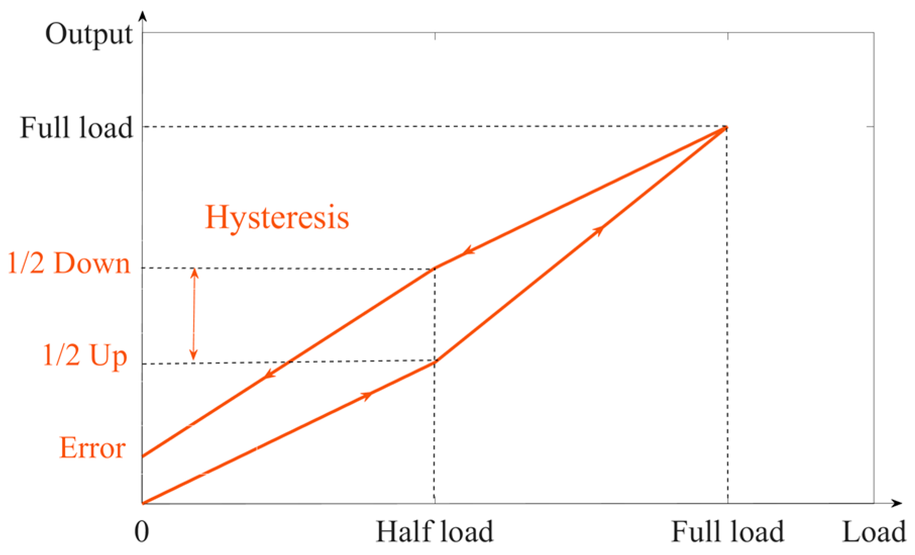
3.5. Fitting Hysteresis—First Load Return-to-Zero Error Curve
4. Experimental Verification
5. Conclusions
- The influence of temperature on hysteresis is small, so the change in temperature has little influence on the return-to-zero error after the first loading.
- The material characteristics are different and there is no weld cup. These factors affect the size of the hysteresis, which in turn affects the return-to-zero error after the first loading.
- The Pearson correlation coefficient shows that the lag and the return-to-zero error after the first load are linearly and strongly correlated. The return-to-zero error after the first load are synthesized into a single function by means of a polynomial curve-fitting algorithm. It is proven that the smaller the hysteresis, the smaller the return-to-zero error after the first loading of the sensor.
- This paper investigates the zero-point error of weight sensors and its relationship with hysteresis, which helps in compensating for the zero-point error. The purpose is to make the load cell more accurate when measuring the weight of an object.
Author Contributions
Funding
Institutional Review Board Statement
Informed Consent Statement
Data Availability Statement
Conflicts of Interest
References
- Abdeetedal, M.; Kermani, R.M. An open-source integration platform for multiple peripheral modules with Kuka robots. CIRP J. Manuf. Sci. Technol. 2019, 27, 46–55. [Google Scholar] [CrossRef]
- Projoth, T.N.; Nanthakumar, P. Analysis and prediction of cutting force through lathe tool dynamometer in CNC turning process. Mater. Today Proc. 2021, 46, 4174–4179. [Google Scholar] [CrossRef]
- Zhang, M.; Qiu, B.; Zhu, M.; Qu, X. Novel computation method of reducing ill-posedness for structural static distributed load identification by optimising strain gauge locations. Mech. Syst. Signal Process. 2019, 124, 83–110. [Google Scholar] [CrossRef]
- Byrne, D.; Esmonde, H.; Berry, D.; McGovern, F.; Creighton, P.; McHugh, N. Sheep lameness detection from individual hoof load. Comput. Electron. Agric. 2019, 158, 241–248. [Google Scholar] [CrossRef]
- Saedin, N.S.; Muttalib, M.F.A.; Jusoh, M.F. Performance Evaluation of Bar Load Cell Sensing System for Soil Moisture Measurement. J. Phys. Conf. Ser. 2023, 2550, 012013. [Google Scholar] [CrossRef]
- Smreczak, M.; Rubbert, L.; Baur, C. Design of a compliant load cell with adjustable stiffness. Precis. Eng. 2021, 72, 259–271. [Google Scholar] [CrossRef]
- Cozzolino, F.; Apicella, D.; Wang, G.; Apicella, A.; Sorrentino, R. Implant-to-bone force transmission: A pilot study for in vivo strain gauge measurement technique. J. Mech. Behav. Biomed. Mater. 2019, 90, 173–181. [Google Scholar] [CrossRef]
- Ramachandran, P.; PradeepKumar, A.R.; Ravishankar, P.; Kishen, A. In Vivo Strain Alterations in Mandibular Molars after Root Canal Treatment Procedures. J. Endod. 2020, 46, 1849–1855. [Google Scholar] [CrossRef]
- Montoro-Bombú, R.; Gomes, B.B.; Santos, A.; Rama, L. Validity and Reliability of a Load Cell Sensor-Based Device for Assessment of the Isometric Mid-Thigh Pull Test. Sensors 2023, 23, 5832. [Google Scholar] [CrossRef]
- Chavarro-Nieto, C.; Beaven, M.; Gill, N.; Hébert-Losier, K. Reliability of Repeated Nordic Hamstring Strength in Rugby Players Using a Load Cell Device. Sensors 2022, 22, 9756. [Google Scholar] [CrossRef]
- Bonito, P.; Sousa, M.; Ferreira, F.J.; Justo, J.F.; Gomes, B.B. Magnitude and Shape of the Forces Applied on the Foot Rest and Paddle by Elite Kayakers. Sensors 2022, 22, 1612. [Google Scholar] [CrossRef] [PubMed]
- Abdulhakim, M.; Hegazy, R.; Abuelezz, A.E.; Abdelhakeem, H.M.; Gaffer, A.M.; Zakaria, H.M. Novel Design of a Multi-Capacity Force Measurement Instrument. Measurement 2020, 173, 108562. [Google Scholar] [CrossRef]
- Templeman, O.J.; Sheil, B.B.; Sun, T. Multi-axis force sensors: A state-of-the-art review. Sens. Actuators A Phys. 2020, 304, 111772. [Google Scholar] [CrossRef]
- Cosentino, I.; Ferro, A.G.; Restuccia, L. An experimental set-up for cyclic loading of concrete. Procedia Struct. Integr. 2020, 25, 413–419. [Google Scholar] [CrossRef]
- Motwani, P.; Perogamvros, N.; Taylor, S.; Laskar, A. Performance of industrial wedge-anchors for pre-stressing BFRP bars: Experimental and numerical studies. Compos. Struct. 2020, 251, 112592. [Google Scholar] [CrossRef]
- Bibbo, D.; Gabriele, S.; Scorza, A.; Schmid, M.; Sciuto, S.A.; Conforto, S. A Novel Technique to Design and Optimize Performances of Custom Load Cells for Sport Gesture Analysis. IRBM 2019, 40, 201–210. [Google Scholar] [CrossRef]
- Moayedi, H.; Mosallanezhad, M. Uplift resistance of belled and multi-belled piles in loose sand. Measurement 2017, 109, 346–353. [Google Scholar] [CrossRef]
- Burcu, D.K.; Tuncay, K. Experimental fault analysis of polymer hybrid bearing using accelerometer and load cell. Tribol. Int. 2023, 185, 108498. [Google Scholar]
- Juyao, L.; Shuang, L.; Yewang, S. Stretchable Strain Sensors Based on Deterministic-Contact-Resistance Braided Structures with High Performance and Capability of Continuous Production. Adv. Funct. Mater. 2022, 32, 08216. [Google Scholar]
- Zhou, C.; Yuan, M.; Feng, C.; Ang, W.T. A Modified Prandtl–Ishlinskii Hysteresis Model for Modeling and Compensating Asymmetric Hysteresis of Piezo-Actuated F lexure-Based Systems. Sensors 2022, 22, 8763. [Google Scholar] [CrossRef]
- Mei, H.; Cheng, L. Comparison of the mechanical hysteresis of carbon/ceramic-matrix composites with different fiber preforms. Carbon 2009, 47, 1034–1042. [Google Scholar] [CrossRef]
- Berry, E.; Hillerton, E. Monitoring mastitis and maintaining biosecurity. Vet. Rec. 2001, 149, 531–532. [Google Scholar]
- Love, A.E.H. A Treatise on the Mathematical Theory of Elasticity; Cambridge University Press: Cambridge, UK, 2013. [Google Scholar]
- Pomerening, J.R.; Sontag, E.D.; Ferrell, J.E., Jr. Building a cell cycle oscillator: Hysteresis and bistability in the activation of Cdc2. Nat. Cell Biol. 2003, 5, 346–351. [Google Scholar] [CrossRef]
- Wang, W.; Wang, R.; Chen, Z.; Sang, Z.; Lu, K.; Han, F.; Wang, J.; Ju, B. A new hysteresis modeling and optimization for piezoelectric actuators based on asymmetric Prandtl-Ishlinskii model. Sens. Actuators A Phys. 2020, 316, 112431. [Google Scholar] [CrossRef]
- Lei, L.; Tan, K.K.; Huang, S.; Lee, T.H. Online parameter estimation and compensation of Preisach hysteresis by SVD updating. IFAC Proc. Vol. 2011, 44, 5249–5254. [Google Scholar] [CrossRef]
- Rivera-Mejia, J.; Villafuerte-Arroyo, J.E.; Vega-Pineda, J.; Sandoval-Rodriguez, R. Comparison of compensation algorithms for smart sensors with approach to real-time or dynamic applications. IEEE Sens. J. 2015, 15, 7071–7080. [Google Scholar] [CrossRef]
- OIML Recommendation. R 76-1: Nonautomatic Weighing Instruments, Part 1: Metro Logical And Technical Requirements-Tests; OIML: Paris, France, 2006. [Google Scholar]
- OIML Recommendation. International Recommendation OIML R 60 Metrological Regulation for Load Cells; OIML: Paris, France, 2000. [Google Scholar]
- Bartel, T.W.; Yaniv, S.L. Creep and creep recovery response of load cells tested according to US and international evaluation procedures. J. Res. Natl. Inst. Stand. Technol. 1997, 102, 349. [Google Scholar] [CrossRef]
- Lin, H.; Li, H.; Shao, G.; Ye, Y.; Yang, Y. Zero-point fault detection of load cells in truck scale based on recursive principal component analysis and comprehensive evaluation method. Measurement 2020, 159, 107706. [Google Scholar] [CrossRef]
- Wang, L.; Cao, T.; Liu, X.; Wang, B.; Jin, K.; Liang, Y.; Wang, L.; Wang, F.; Ren, Y.; Liang, J.; et al. A novel stress-induced martensitic transformation in a single-phase refractory high-entropy alloy. Scr. Mater. 2020, 189, 129–134. [Google Scholar] [CrossRef]
- Yi, J.H.; Kim, J.H. Temperature dependence of zero point in force transducers II: How to account for the effects of a zero balancing resistor. Exp. Tech. 2016, 40, 221–225. [Google Scholar] [CrossRef]
- Paredes-Madrid, L.; Matute, A.; Peña, A. Framework for a calibration-less operation of force sensing resistors at different temperatures. IEEE Sens. J. 2017, 17, 4133–4142. [Google Scholar] [CrossRef]
- Rosolem, J.B.; Penze, R.S.; Floridia, C.; Peres, R.; Vasconcelos, D.; Ramos, M.A., Jr. Techniques and Materials for Optical Fiber Sensors Sealing in Dynamic Environments with High Pressure and High Temperature. Sensors 2021, 21, 6531. [Google Scholar] [CrossRef]
- Bebr, L.; Bícová, K.; Zídková, H. Use of the ppm and its function in the production process. Procedia Manuf. 2017, 13, 608–615. [Google Scholar] [CrossRef]
- Felippe, H.; Viol, A.; De Araujo, D.B.; Da Luz, M.G.; Palhano-Fontes, F.; Onias, H.; Raposo, E.P.; Viswanathan, G.M. Threshold-free estimation of entropy from a Pearson matrix. Europhys. Lett. 2023, 141, 31003. [Google Scholar] [CrossRef]
- Yang, Y.; Xu, T.; Sun, Z.; Nie, W.; Fang, Z. Middle-and Long-Term UT1-UTC Prediction Based on Constrained Polynomial Curve Fitting, Weighted Least Squares and Autoregressive Combination Model. Remote Sens. 2022, 14, 3252. [Google Scholar] [CrossRef]


| Material Name | Density/(kg·m−3) | Young’s Modulus /GPa | Poisson’s Ratio |
|---|---|---|---|
| Q45 | 7890 | 200 | 0.269 |
| Temperature Conditions | Zero Point (g) |
|---|---|
| 20 °C | 0 |
| After load at 20 °C | 43 |
| 40 °C | −40 |
| After load at 40 °C | 7 |
| −10 °C | 35 |
| After load at −10 °C | 100 |
| 5 °C | −17 |
| After load at 5 ℃ | 29 |
| 20 °C | −55 |
| After load at 20 °C | −11 |
| Temperature Conditions 9 (°C) | ΔZ (g) |
|---|---|
| 20 | 43 |
| 40 | 47 |
| −10 | 65 |
| 5 | 46 |
| 20 | 44 |
| Zero Point Change | With Weld Cup | Without Weld Cup |
|---|---|---|
| ΔZ1 (ppm) | 254.6 | −54.6 |
| ΔZ2 (ppm) | 18.2 | −18.2 |
| ΔZ3 (ppm) | 13.6 | −9.1 |
| ΔZ4 (ppm) | 4.6 | 0 |
| Type | With Weld Cup | Without Weld Cup |
|---|---|---|
| Hysteresis (ppm) | 305 | −275 |
| Number | SS1 | SS2 | SS3 | SS4 | SS5 | AS1 | AS2 | AS3 | AS4 | AS5 |
|---|---|---|---|---|---|---|---|---|---|---|
| ΔZ1 (ppm) | 305 | 305 | 335 | 285 | 185 | −63 | −36 | −71 | −75 | −20 |
| ΔZ2 (ppm) | 4 | 1 | 3 | 2 | 0 | 1 | 0 | −1 | −1 | 0 |
| ΔZ3 (ppm) | 1 | 0 | 0 | 1 | 0 | 0 | 0 | 0 | 0 | 0 |
| Number | SS1 | SS2 | SS3 | SS4 | SS5 | AS1 | AS2 | AS3 | AS4 | AS5 |
|---|---|---|---|---|---|---|---|---|---|---|
| ΔZ1 (ppm) | 305 | 305 | 335 | 285 | 185 | −63 | −36 | −71 | −75 | −20 |
| Hysteresis (ppm) | 360 | 360 | 360 | 260 | 220 | −74 | −53 | −104 | −106 | −32 |
| X (ppm) | Y (ppm) | X (ppm) | Y (ppm) | X (ppm) | Y (ppm) | X (ppm) | Y (ppm) | X (ppm) | Y (ppm) |
|---|---|---|---|---|---|---|---|---|---|
| −106 | −75 | 360 | 305 | 123 | 94 | 59 | 35 | 240 | 208 |
| −104 | −71 | 360 | 335 | 115 | 101 | 64 | 45 | 10 | 9 |
| −74 | −63 | −13 | −8 | 130 | 102 | 22 | 59 | 6 | 7 |
| −53 | −36 | −23 | −17 | 122 | 98 | 33 | 45 | −5 | −10 |
| −32 | −20 | −50 | −45 | 110 | 72 | 40 | 59 | ||
| 220 | 285 | −56 | −49 | 72 | 42 | 160 | 153 | ||
| 360 | 305 | 100 | 102 | 89 | 49 | 145 | 111 |
| Number | S1 | S2 | S3 | S4 | S5 | S6 |
|---|---|---|---|---|---|---|
| Hysteresis (ppm) | 3 | 5 | 4 | 6 | 2 | 5 |
| ΔZ (ppm) | 2 | 1 | 4 | 2 | 0 | 2 |
Disclaimer/Publisher’s Note: The statements, opinions and data contained in all publications are solely those of the individual author(s) and contributor(s) and not of MDPI and/or the editor(s). MDPI and/or the editor(s) disclaim responsibility for any injury to people or property resulting from any ideas, methods, instructions or products referred to in the content. |
© 2023 by the authors. Licensee MDPI, Basel, Switzerland. This article is an open access article distributed under the terms and conditions of the Creative Commons Attribution (CC BY) license (https://creativecommons.org/licenses/by/4.0/).
Share and Cite
Zhuang, S.; Yang, W.; Cheng, X.; Kevin, J.S.; Liu, C.; Zhang, G.; Zhu, W.; Tian, C. Analysis of Return-to-Zero Error after the First Load of Load Cell. Sensors 2023, 23, 8712. https://doi.org/10.3390/s23218712
Zhuang S, Yang W, Cheng X, Kevin JS, Liu C, Zhang G, Zhu W, Tian C. Analysis of Return-to-Zero Error after the First Load of Load Cell. Sensors. 2023; 23(21):8712. https://doi.org/10.3390/s23218712
Chicago/Turabian StyleZhuang, Shudong, Wen Yang, Xianming Cheng, Jenny Sama Kevin, Chang Liu, Guangjie Zhang, Wenbin Zhu, and Chengdong Tian. 2023. "Analysis of Return-to-Zero Error after the First Load of Load Cell" Sensors 23, no. 21: 8712. https://doi.org/10.3390/s23218712