

Tool Frame Calibration for Robot-Assisted Ultrasonic Testing


Abstract
:1. Introduction
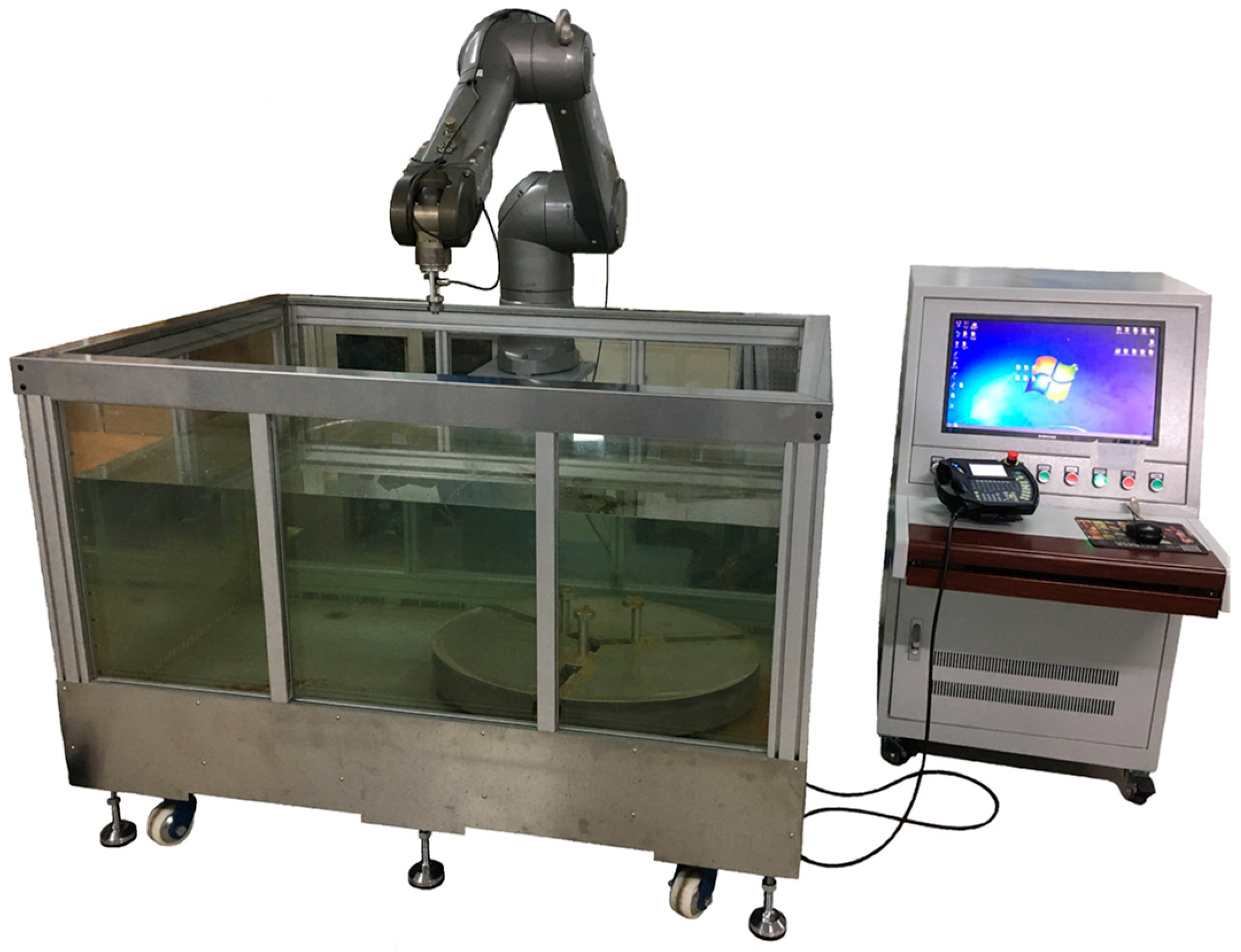
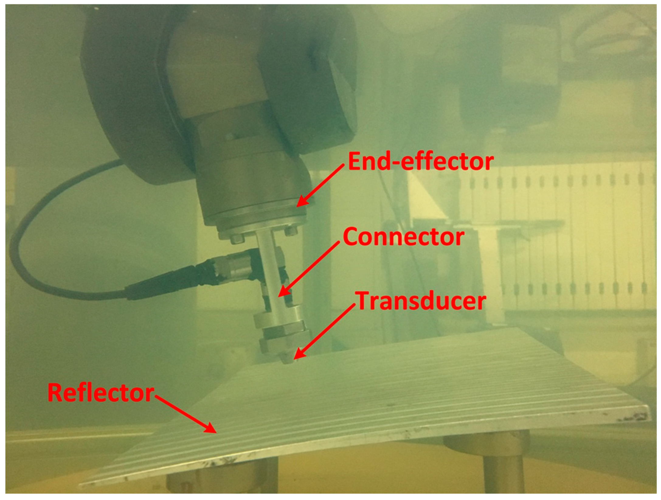
2. System Construction
3. Optimization-Based Calibration Method
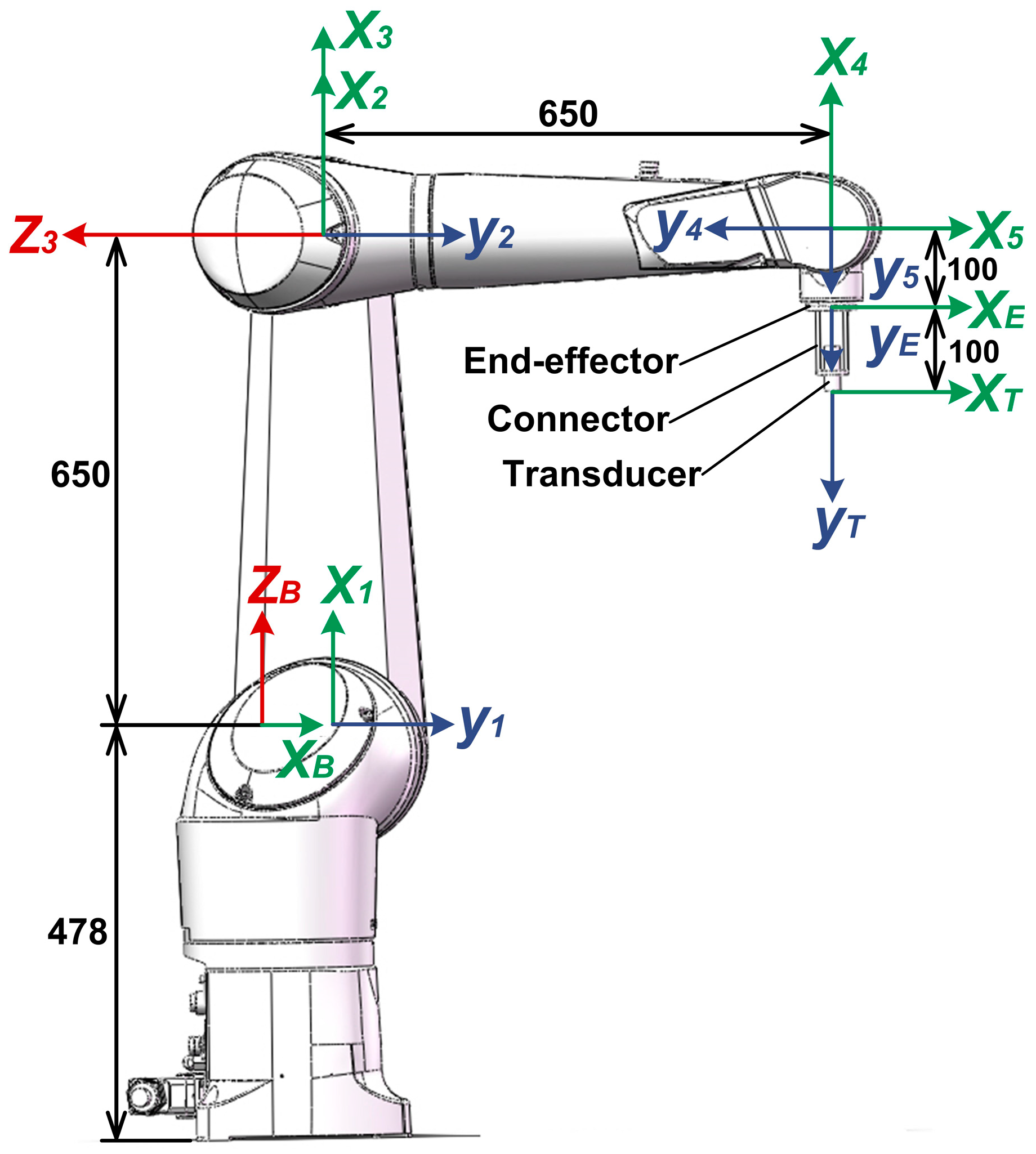
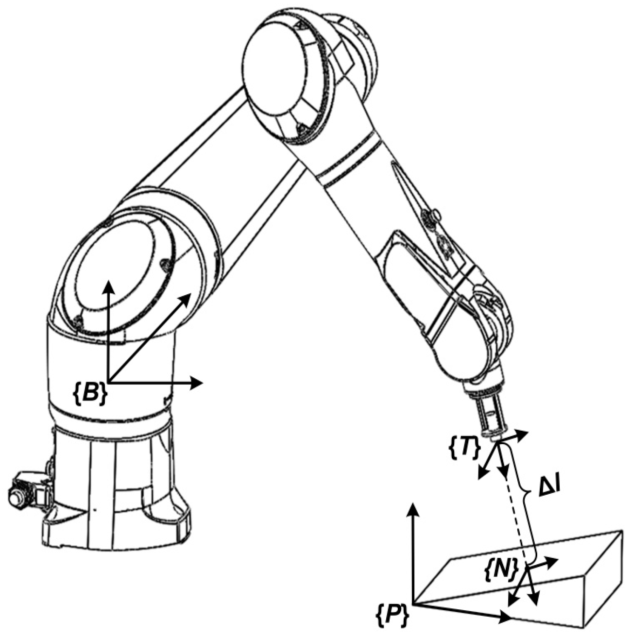
3.1. Robot Kinematic Model
3.2. Error Calibration
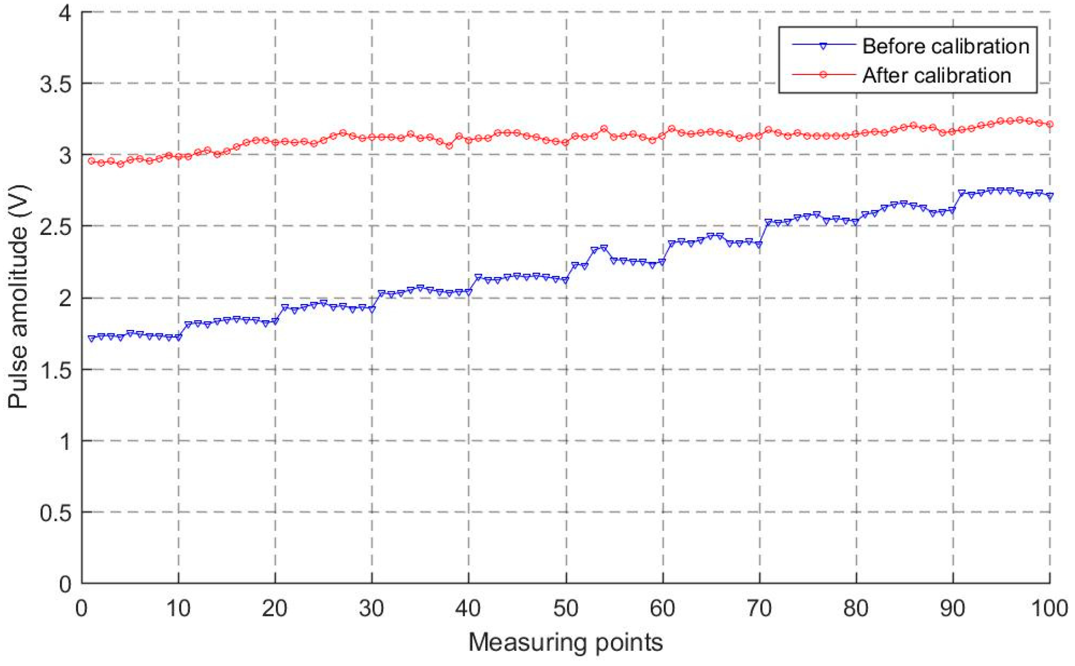
4. Experiment Results
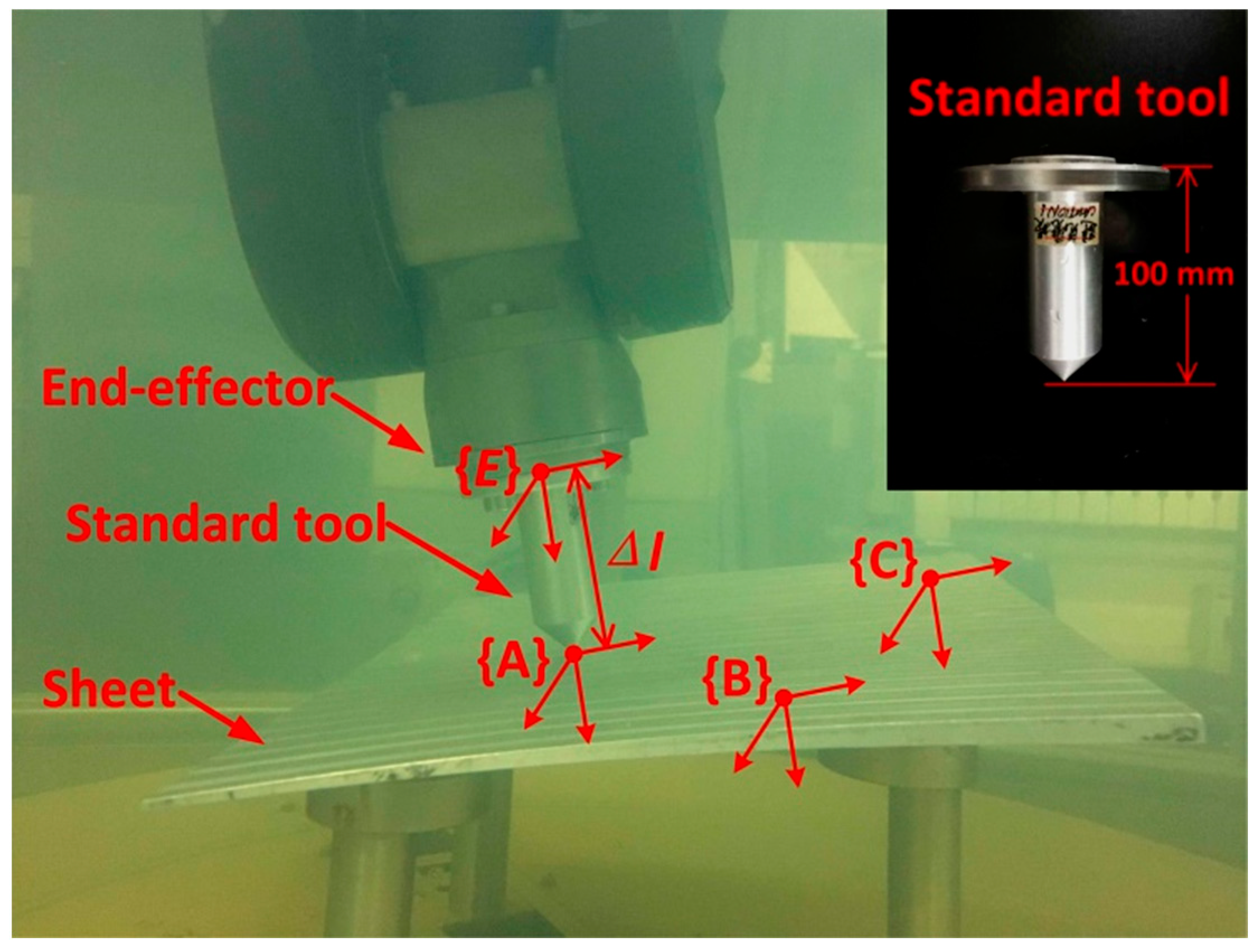
- Step 1
- The robot is operated by making the standard tool contact the board with an arbitrary pose;
- Step 2
- The position coordinates of the contact point (such as A) relative to {B} are calculated through equation (6);
- Step 3
- Step 1 and 2 are repeated three times to acquire the position coordinates of point A, B, and C.
- Step 4
- The plane equation is calculated according to Equation (10).
5. Conclusions
- (1)
- A robot-assisted system which is more suitable to test complex curved parts compared with frame-type scan machines is proposed.
- (2)
- The DH model is used to describe the statical relationship of each component. The tool frame calibration is modelled and translated into a mathematical problem to calculate the values in .
- (3)
- The calculation is described as a constrained non-linear optimization problem, then it is transformed into a linear optimization problem that can be solved by iteration.
- (4)
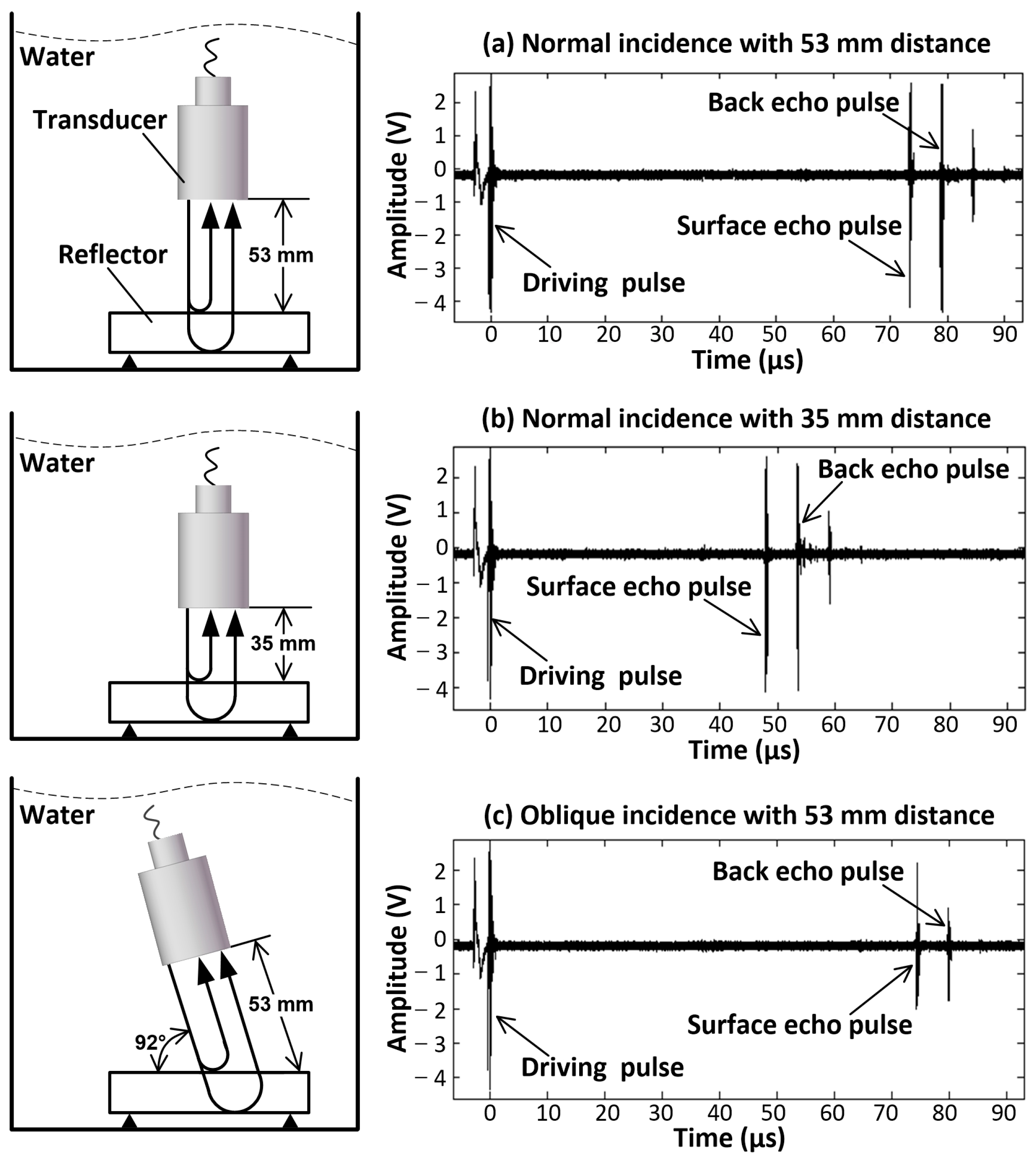
- In this experiment, we find that the incidence points should be scattered on the reflector; the propagation distance should be different on each incidence point; and the transducer pose should be distributed in different angles.
Author Contributions
Funding
Institutional Review Board Statement
Informed Consent Statement
Data Availability Statement
Conflicts of Interest
References
- Liu, S.; Liu, F.; Yang, Y.; Li, L.; Li, Z. Nondestructive Evaluation 4.0: Ultrasonic Intelligent Nondestructive Testing and Evaluation for Composites. Res. Nondestruct. Eval. 2020, 31, 370–388. [Google Scholar]
- Mineo, C.; MacLeod, C.; Morozov, M.; Pierce, S.G.; Lardner, T.; Summan, R.; Powell, J.; McCubbin, P.; McCubbin, C.; Munro, G.; et al. Fast ultrasonic phased array inspection of complex geometries delivered through robotic manipulators and high speed data acquisition instrumentation. In Proceedings of the IEEE International Ultrasonics Symposium (IUS), Tours, France, 18–21 September 2016. [Google Scholar]
- Guo, C.; Xu, C.; Hao, J.; Xiao, D.; Yang, W. Ultrasonic Non-Destructive Testing System of Semi-Enclosed Workpiece with Dual-Robot Testing System. Sensors 2019, 19, 3359. [Google Scholar] [CrossRef]
- Feng, X.; Tian, D.; Wu, H.; Qian, C.; Zhu, D. A matrix-solving hand-eye calibration method considering robot kinematic errors. J. Manuf. Process 2023, 99, 618–635. [Google Scholar]
- Guo, Y.; Song, B.; Tang, X.Q.; Zhou, X.D.; Xie, Y.L.; Jin, J. Calibration for kinematic parameters of industrial robot by a laser displacement sensor. In Proceedings of the International Conference on Control, Automation, Robotics and Vision (ICARCV), Singapore, 18–21 November 2018. [Google Scholar]
- Lin, C.J.; Wang, H.C.; Wang, C.C. Automatic Calibration of Tool Center Point for Six Degree of Freedom Robot. Actuators 2023, 12, 107. [Google Scholar] [CrossRef]
- Renders, J.M.; Rossignol, E.; Becquet, M.; Hanus, R. Kinematic calibration and geometrical parameter identification for robots. IEEE T. Robotic. Autom. 1991, 7, 721–732. [Google Scholar] [CrossRef]
- Driels, M.R.; Swayze, W.E. Automated partial pose measurement system for manipulator calibration experiments. IEEE Trans. Robot. Autom. 1994, 10, 430–440. [Google Scholar] [CrossRef]
- Liu, Y.; Zhuang, Z.; Li, Y. Closed-Loop Kinematic calibration of robots using a six-point measuring device. IEEE Trans. Instrum. Meas. 2022, 71, 1–12. [Google Scholar]
- Tang, X.; Zhou, H.; Xu, T. A geometric errors identification method for the rotating axis of five-axis welding equipment. Int. J. Precis. Eng. Manuf. 2023, 24, 1355–1367. [Google Scholar] [CrossRef]
- Xiao, P.; Ju, H.; Li, Q.; Meng, J.; Chen, F. A new fixed axis-invariant based calibration approach to improve absolute positioning accuracy of manipulators. IEEE Access 2020, 8, 134224–134232. [Google Scholar]
- Soichi, I.; Ryota, U. A novel error mapping of bi-directional angular positioning deviation of rotary axes in a SCARA-type robot by “open-loop” tracking interferometer measurement. Precis. Eng. 2022, 74, 60–68. [Google Scholar]
- Gharaaty, S.; Shu, T.; Joubair, A.; Xie, W.; Bonev, I.A. Online pose correction of an industrial robot using an optical coordinate measure machine system. Int. J. Adv. Robot. Syst. 2018, 15, 1729881418787915. [Google Scholar]
- Chen, I.-M.; Yang, G.; Tan, C.T.; Yeo, S.H. Local POE model for robot kinematic calibration. Mech. Mach. Theory 2001, 36, 1215–1239. [Google Scholar]
- Omodei, A.; Legnani, G.; Adamini, R. Three Methodologies for the Calibration of Industrial Manipulators: Experimental Results on a SCARA Robot. J. Robot. Syst. 2000, 17, 291–307. [Google Scholar]
- Chang, P.; Li, C.; Li, T. Kinematic calibration and forecast error compensation of a 2-DOF planar parallel manipulator. Chin. J. Mech. Eng. 2011, 24, 992–998. [Google Scholar]
- Ma, H.W.; Zhang, X.H.; Wei, J. Research on an ultrasonic NDT system for complex surface parts. J. Mater. Process. Technol. 2002, 129, 667–670. [Google Scholar]
- Aparicio Secanellas, S.; Gauna León, I.; Parrilla, M.; Acebes, M.; Ibáñez, A.; de Matías Jiménez, H.; Martínez-Graullera, Ó.; Álvarez de Pablos, A.; González Hernández, M.; Anaya Velayos, J.J. Methodology for the Generation of High-Quality Ultrasonic Images of Complex Geometry Pieces Using Industrial Robots. Sensors 2023, 23, 2684. [Google Scholar]


| Link | θi [°] | di [mm] | ai [mm] | αi [°] |
|---|---|---|---|---|
| 1 | θ1 | 0 | 50 | −90 |
| 2 | θ2−90° | 50 | 650 | 0 |
| 3 | θ3 | 0 | 0 | 90 |
| 4 | θ4 | −650 | 0 | 90 |
| 5 | θ5−90° | 0 | 0 | 90 |
| 6 | θ6 | 100 | 0 | 0 |
| i | xi (mm) | yi (mm) | zi (mm) |
|---|---|---|---|
| 1 | 1035.06 | 366.72 | −814.92 |
| 2 | 1035.04 | 519.10 | −794.92 |
| 3 | 992.91 | 509.89 | −796.71 |
| 4 | 992.96 | 341.27 | −819.36 |
| 5 | 956.59 | 361.46 | −817.28 |
| 6 | 956.56 | 536.33 | −793.95 |
| 7 | 836.25 | 536.20 | −795.29 |
| 8 | 844.11 | 371.18 | −817.68 |
| 9 | 726.88 | 384.30 | −816.16 |
| Axis | Position Error (mm) | Angle Error (mm) |
|---|---|---|
| X | 0.48 | 0.12 |
| Y | 1.48 | 1.22 |
| Z | 4.45 | 0.13 |
Disclaimer/Publisher’s Note: The statements, opinions and data contained in all publications are solely those of the individual author(s) and contributor(s) and not of MDPI and/or the editor(s). MDPI and/or the editor(s) disclaim responsibility for any injury to people or property resulting from any ideas, methods, instructions or products referred to in the content. |
© 2023 by the authors. Licensee MDPI, Basel, Switzerland. This article is an open access article distributed under the terms and conditions of the Creative Commons Attribution (CC BY) license (https://creativecommons.org/licenses/by/4.0/).
Share and Cite
Zhang, H.; Wang, J.; Guo, C. Tool Frame Calibration for Robot-Assisted Ultrasonic Testing. Sensors 2023, 23, 8820. https://doi.org/10.3390/s23218820
Zhang H, Wang J, Guo C. Tool Frame Calibration for Robot-Assisted Ultrasonic Testing. Sensors. 2023; 23(21):8820. https://doi.org/10.3390/s23218820
Chicago/Turabian StyleZhang, Hanming, Jingpin Wang, and Canzhi Guo. 2023. "Tool Frame Calibration for Robot-Assisted Ultrasonic Testing" Sensors 23, no. 21: 8820. https://doi.org/10.3390/s23218820
APA StyleZhang, H., Wang, J., & Guo, C. (2023). Tool Frame Calibration for Robot-Assisted Ultrasonic Testing. Sensors, 23(21), 8820. https://doi.org/10.3390/s23218820