Design of a Tripod-Shaped Radiator Patch Antenna for Ultra-Wideband Direction Finding


Abstract
:1. Introduction
2. Design of the Tripod-Shaped SRMP Antenna
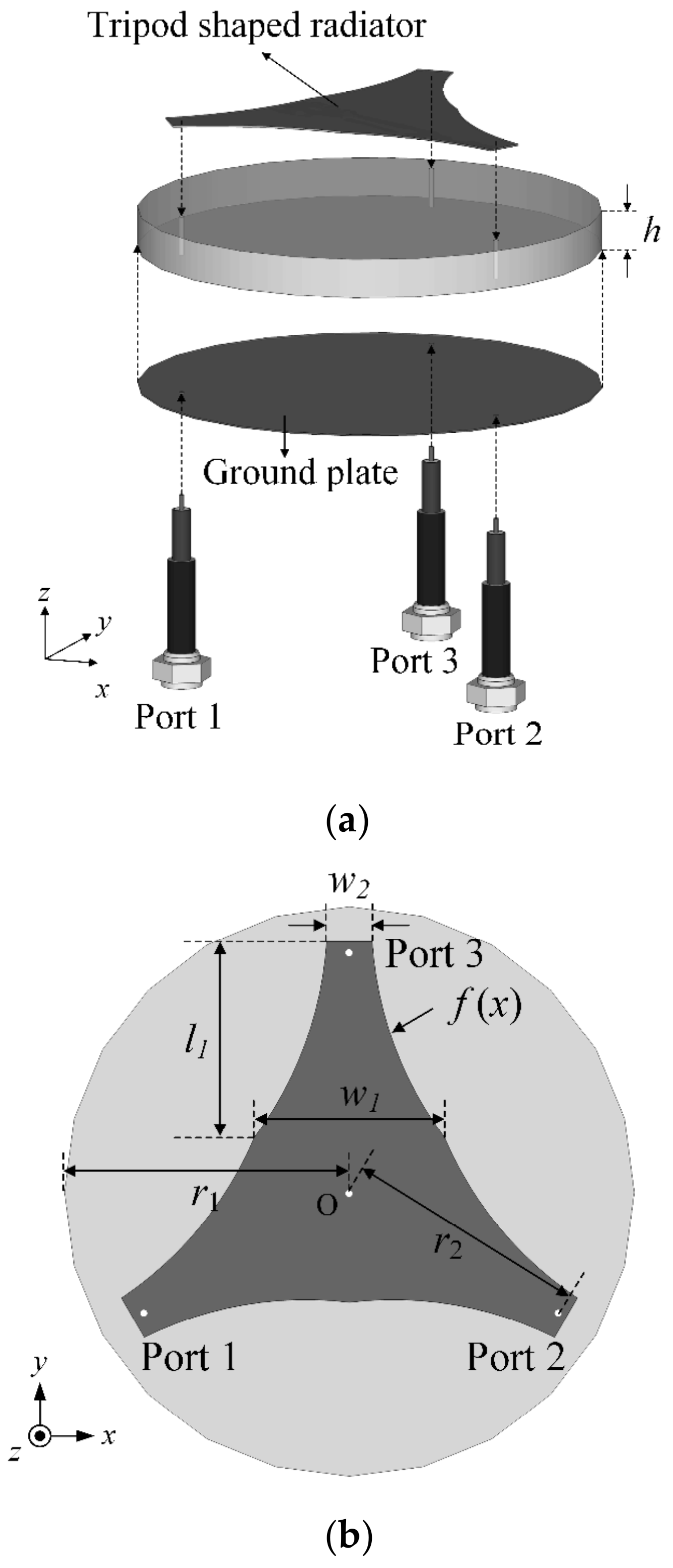
2.1. Proposed SRMP Antenna Design
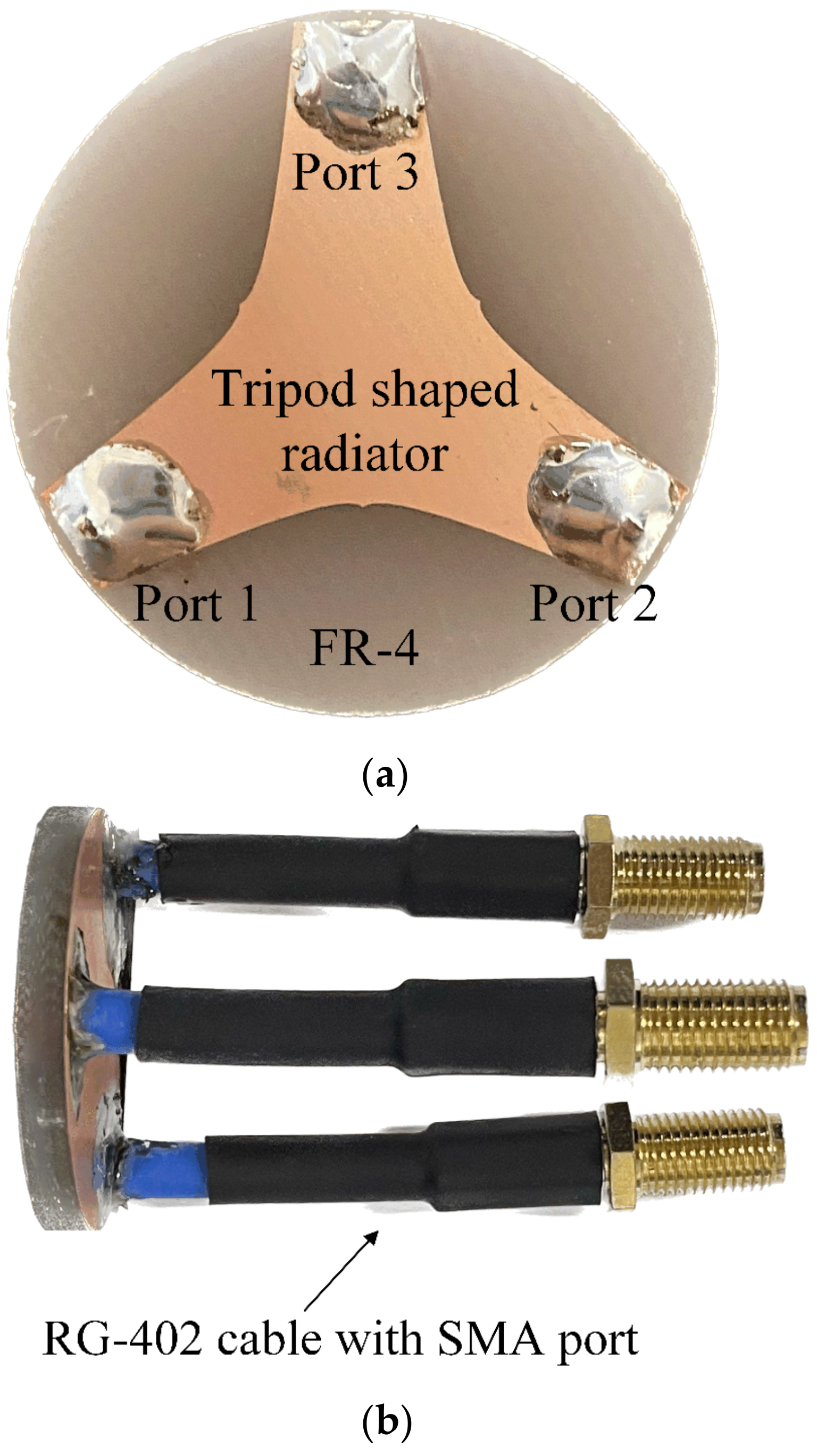
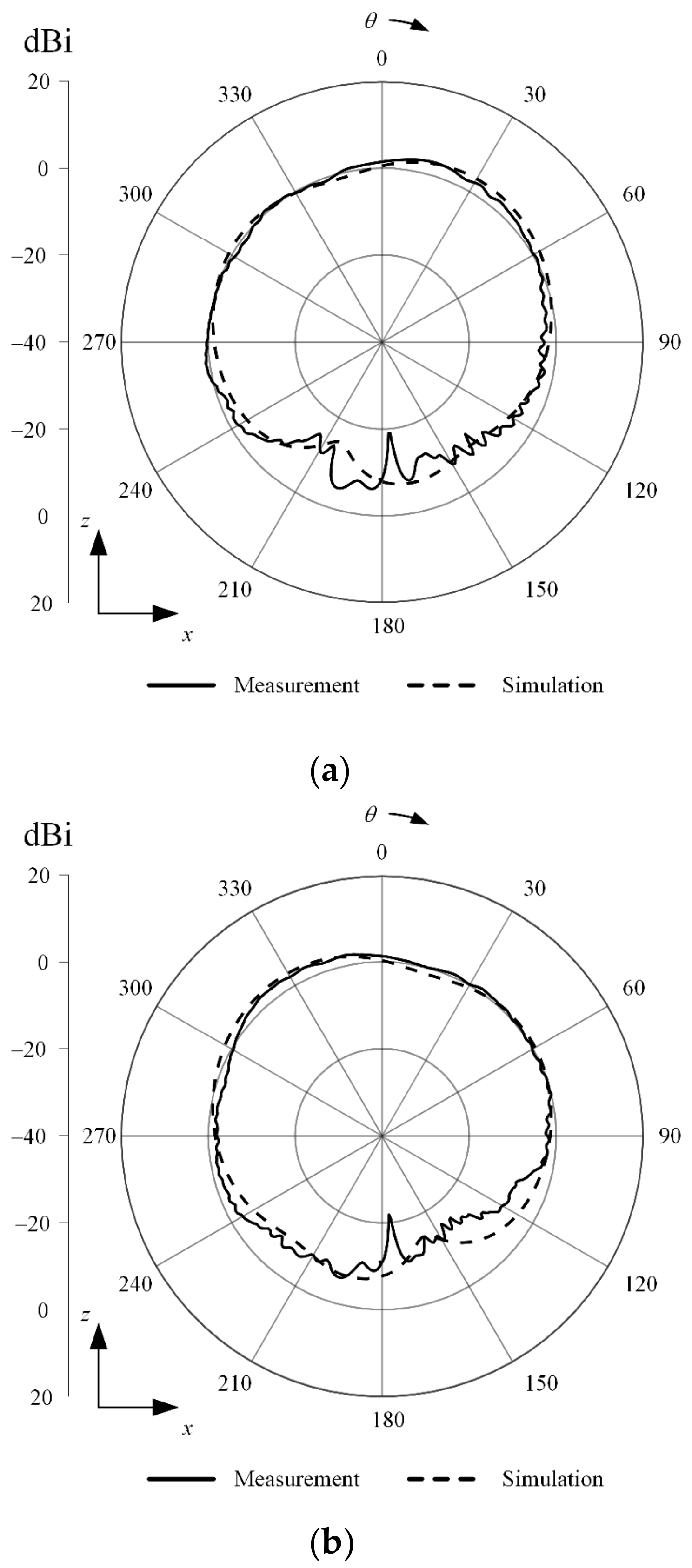
2.2. Fabrication and Measurement Results
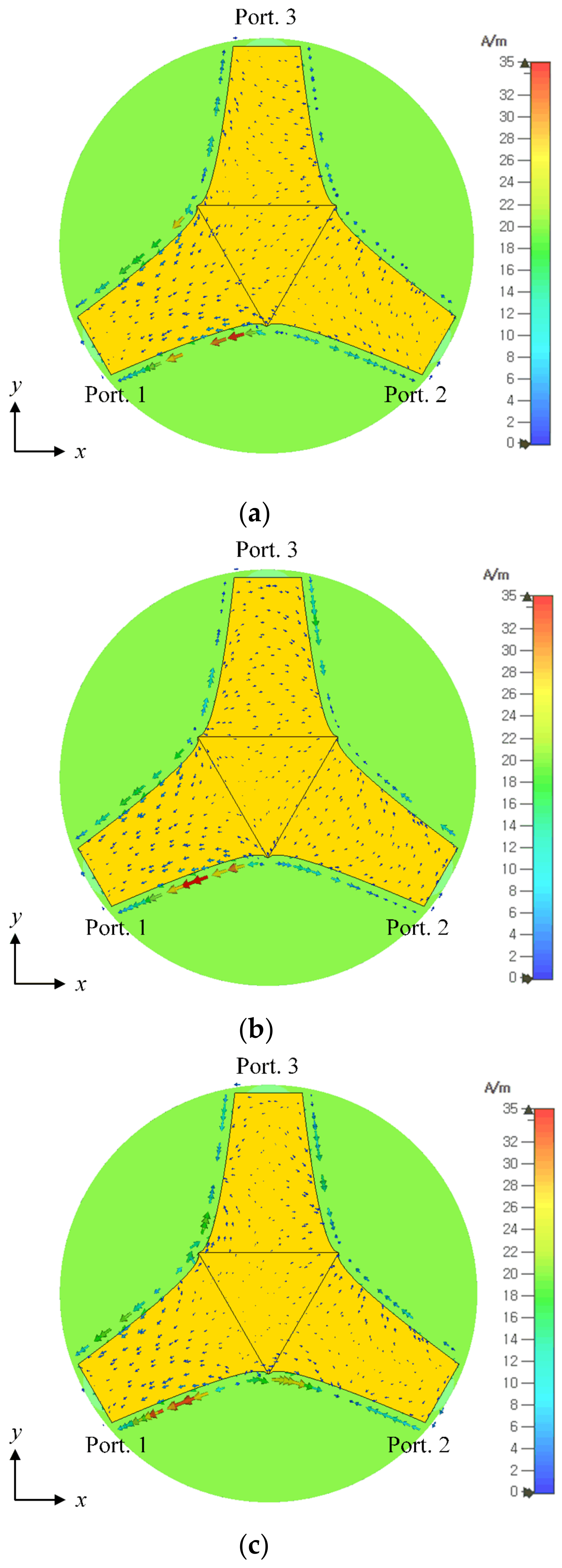
2.3. Optimization Using Design Parameters
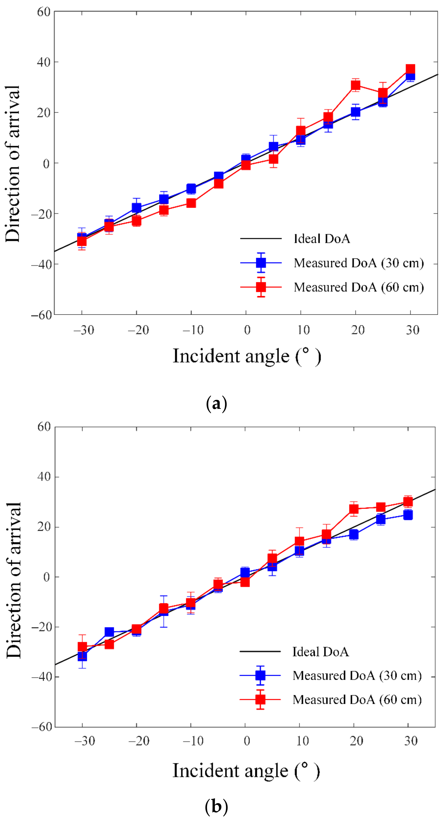
3. DoA Estimation Using the CIR Data
4. Conclusions
Author Contributions
Funding
Institutional Review Board Statement
Informed Consent Statement
Data Availability Statement
Conflicts of Interest
References
- Fontaine, J.; Van Herbruggen, B.; Shahid, A.; Kram, S.; Stahlke, M.; De Poorter, E. Ultra Wideband (UWB) Localization Using Active CIR-Based Fingerprinting. IEEE Commun. Lett. 2023, 27, 1322–1326. [Google Scholar]
- Deng, X.; Ping, Z.; Sun, R. UWB NLOS Recognition Based on Improved Convolutional Neural Network Assisted by Wavelet Analysis and Gramian Angular Field. IEEE Sens. J. 2023, 12, 16384–16392. [Google Scholar]
- Abusharkra, F.; Jeong, N.; Elluru, D.N.; Awasthi, A.K.; Kolpuke, S.; Luong, T.; Reyhanigalangashi, O.; Taylor, D.; Prasad Gogineni, S. A Miniaturized Ultra-Wideband Radar for UAV Remote Sensing Applications. IEEE Microw. Wirel. Compon. Lett. 2021, 32, 198–201. [Google Scholar]
- An, X.; Wagner, J.; Ellinger, F. An Integrated Primary Impulse Radio Ultra-Wideband Radar for Short-Range Real-Time Localization. IEEE Trans. Circuits Syst. I-Regul. Pap. 2022, 69, 3190–3201. [Google Scholar]
- Su, W.; Prasannakumar, P.V.; Li, Y.; Ye, G.; Zhu, J. Wearable Antennas for Virtual Reality Cross-Body Links. IEEE Open J. Antennas Propag. 2023, 4, 207–215. [Google Scholar]
- Senevirathna, N.M.; De Silva, O.; Mann, G.K.I.; Gosine, R.G. Asymptotic Gradient Clock Synchronization in Wireless Sensor Networks for UWB Localization. IEEE Sens. J. 2022, 22, 24578–24592. [Google Scholar]
- Constanzo, A.; Dardari, D.; Aleksandravicius, J.; Decarli, N.; Del Prete, M.; Fabbri, D.; Fantuzzi, M.; Guerra, A.; Masotti, D.; Pizzotti, M.; et al. Energy Autonomous UWB Localization. IEEE J. Radio Freq. Identif. 2017, 1, 228–244. [Google Scholar]
- Li, Z.; Dehaene, W. A 3-tier UWB-based indoor localization system for ultra-low-power sensor networks. IEEE Trans. Wirel. Commun. 2009, 8, 2813–2818. [Google Scholar] [CrossRef]
- Zhang, H.; Wang, Q.; Xu, J.; Li, Z.; Yang, Y. Time Delay Characteristics Analysis of UWB Diffraction Propagation in Indoor NLOS Environment. IEEE Commun. Lett. 2022, 27, 1889–1893. [Google Scholar]
- Che, F.; Ahmed, Q.Z.; Fontaine, J.; Van Herbruggen, B.; Shahid, A.; De Poorter, E.; Lazaridis, P.I. Feature-Based Generalized Gaussian Distribution Method for NLoS Detection in Ultra-Wideband (UWB) Indoor Positioning System. IEEE Sens. J. 2022, 22, 18726–18739. [Google Scholar]
- Marano, S.; Gifford, W.M.; Wymeersch, H.; Win, M.Z. NLOS identification and mitigation for localization based on UWB experimental data. IEEE J. Sel. Areas Commun. 2010, 28, 1026–1035. [Google Scholar]
- Dong, M. A Low-Cost NLOS Identification and Mitigation Method for UWB Ranging in Static and Dynamic Environments. IEEE Commun. Lett. 2010, 25, 2420–2424. [Google Scholar]
- Feghhi, R.; Winter, R.S.C.; Sabzevari, F.M.; Rambabu, K. Design of a Low-Cost UWB Time-Domain Radar System for Subcentimeter Image Resolution. IEEE Trans. Microw. Theory Tech. 2022, 70, 3617–3628. [Google Scholar]
- Mekki, K.; Necibi, O.; Lakhdhar, S.; Gharsallah, A. A UHF/UWB Monopole Antenna Design Process Integrated in an RFID Reader Board. J. Electromagn. Eng. Sci. 2022, 22, 479–487. [Google Scholar]
- Cano, J.; Pagès, G. Clock and Power-Induced Bias Correction for UWB Time-of-Flight Measurements. IEEE Robot. Autom. Lett. 2022, 7, 2431–2438. [Google Scholar]
- Pochanin, G.P.; Capineri, L.; Bechtel, T.D.; Falorni, P.; Borgioli, G.; Ruban, V.P.; Orlenko, O.A.; Ogurtsova, T.M.; Pochanin, O.G.; Crawford, F.; et al. Measurement of Coordinates for a Cylindrical Target Using Times of Flight from a 1-Transmitter and 4-Receiver UWB Antenna System. IEEE Trans. Geosci. Remote Sens. 2019, 58, 1363–1372. [Google Scholar]
- Taponecco, L.; D’Amico, A.A.; Mengali, U. Joint TOA and AOA Estimation for UWB Localization Applications. IEEE Trans. Wirel. Commun. 2011, 10, 2207–2217. [Google Scholar] [CrossRef]
- Tan, A.E.C.; Chia, M.Y.W.; Rambabu, K. Effect of Antenna Noise on Angle-of-Arrival Estimation of Ultrawideband Receivers. IEEE Trans. Electromagn. Compat. 2011, 53, 11–17. [Google Scholar]
- Lin, Z.; Niu, H.; An, K.; Hu, Y.; Li, D.; Wang, J.; Al-Dhahir, N. Pain without Gain: Destructive Beamforming from A Malicious RIS Perspective in IoT Networks. IEEE Internet Things J. 2023, 1, 1–11. [Google Scholar]
- Lin, Z.; Liu, M.; Champagne, B.; Zhu, W.P.; Al-Dhahir, N. Secrecy-Energy Efficient Hybrid Beamforming for Satellite-Terrestrial Integrated Networks. IEEE Trans. Commun. 2021, 9, 6345–6360. [Google Scholar]
- Sun, Y.; An, K.; Zhu, Y.; Zheng, G.; Wong, K.K.; Chatzinotas, S.; Ng, D.W.K.; Guan, D. Energy-Efficient Hybrid Beamforming for Multilayer RIS-Assisted Secure Integrated Terrestrial-Aerial Networks. IEEE Trans. Commun. 2022, 70, 4189–4210. [Google Scholar]
- Sun, Y.; An, K.; Zhu, Y.; Zheng, G.; Wong, K.K.; Chatzinotas, S.; Yin, H.; Liu, P. RIS-Assisted Robust Hybrid Beamforming Against Simultaneous Jamming and Eavesdropping Attacks. IEEE Trans. Wirel. Commun. 2022, 11, 9212–9231. [Google Scholar]
- Koziel, S.; Bekasiewich, A. A Structure and Simulation-Driven Design of Compact CPW-Fed UWB Antenna. IEEE Antennas Wirel. Propag. Lett. 2015, 15, 750–753. [Google Scholar]
- Luo, C.M.; Hong, J.S.; Zhong, L.L. Isolation Enhancement of a Very Compact UWB-MIMO Slot Antenna with Two Defected Ground Structures. IEEE Antennas Wirel. Propag. Lett. 2015, 14, 1766–1769. [Google Scholar]
- Li, T.; Zhai, H.; Li, L.; Liang, C.; Han, Y. Compact UWB Antenna with Tunable Band-Notched Characteristic Based on Microstrip Open-Loop Resonator. IEEE Antennas Wirel. Propag. Lett. 2012, 11, 1584–1587. [Google Scholar]
- Chen, Z.; Song, W.; Wang, W. Wideband Millimeter-Wave MIMO Antenna with a Loaded Dielectric Cover for High-Gain Broadside Radiation. Electronics 2023, 12, 4384. [Google Scholar]
- Mistri, R.K.; Mahto, S.K.; Singh, A.K.; Sinha, R.; Al-Ghuri, A.J.A.; Alghamdi, T.A.H.; Alathbah, M. Quad Element MIMO Antenna for C, X, Ku, and Ka-Band Applications. Sensors 2023, 23, 8563. [Google Scholar]
- Lee, J.N.; Hyun, S.B.; Cho, Y.K. A Compact Ultra-Wideband Chip Antenna with Bandwidth Extension Patch and Simple Isolator for MIMO Systems for Mobile Handheld Terminals. J. Electromagn. Eng. Sci. 2022, 22, 272–282. [Google Scholar]
- Kang, H.; Youn, S.; Choo, H. Design of a Single Circular Radiator with Multiple Patterns for a UWB Three-Axis Monopulse System. IEEE Access 2023, 11, 83887–83895. [Google Scholar]
- CST Microwave Studio. Available online: http://www.cst.com (accessed on 19 October 2023).
- IEEE 802.15.4z-2022; IEEE Standard for Low-Rate Wireless Networks; Amendment to IEEE Std 802.14-4-2020. IEEE: Manhattan, NY, USA, 2020.


| Parameter | Optimized Value |
|---|---|
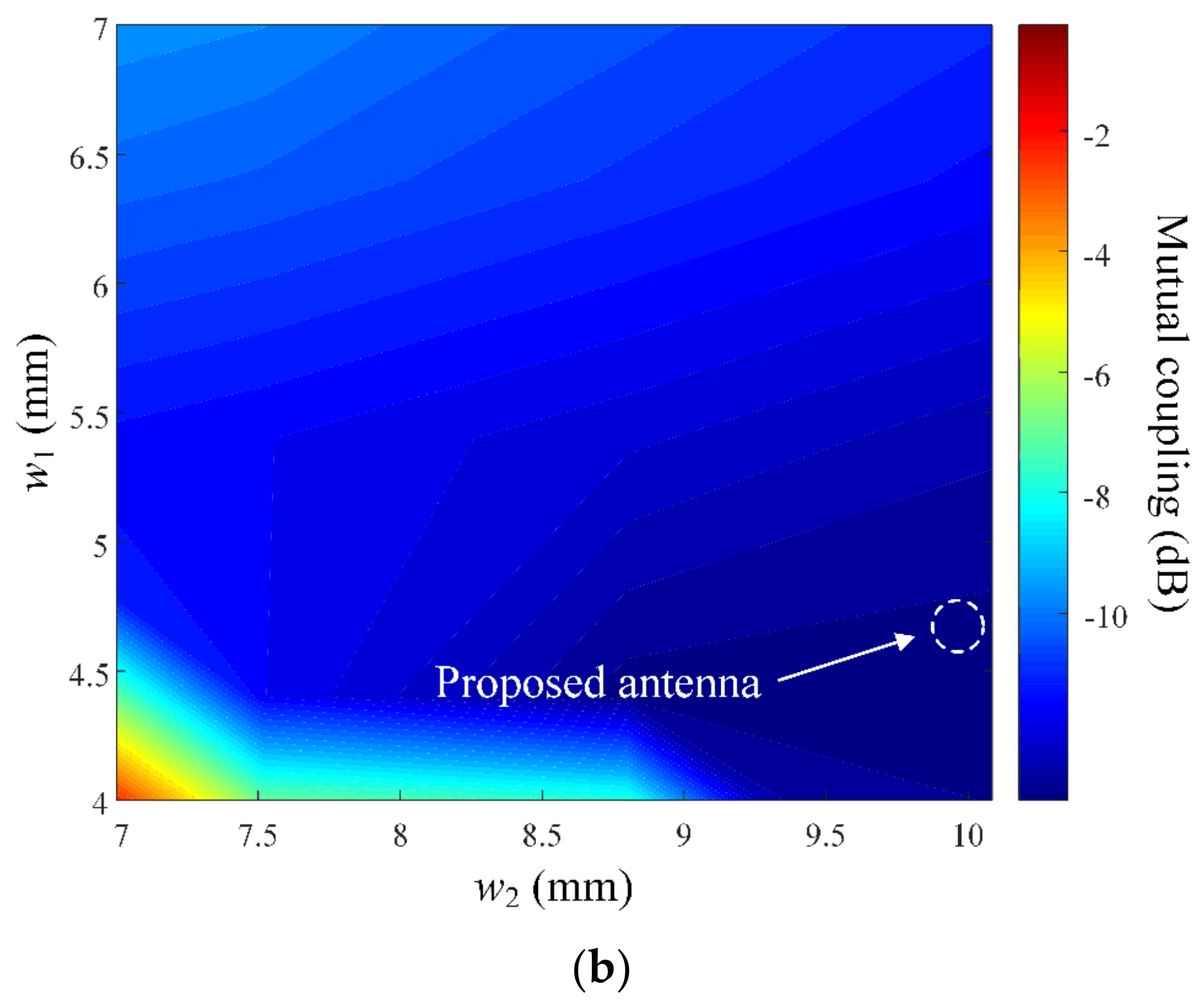
| w1 | 10.1 mm |
| w2 | 4.87 mm |
| l1 | 11.7 mm |
| r1 | 15.05 mm |
| r2 | 12.8 mm |
| h | 3.2 mm |
| Proposed Antenna | Previous Publication [29] | [26] | [27] | |
|---|---|---|---|---|
| Aperture size | 30.1 mm (0.8 λ at 8 GHz) | 36 mm (0.96 λ at 8 GHz) | 23.9 mm (5.1 λ at 64 GHz) | 105 mm (1.05 λ at 3 GHz) |
| Operating frequency | 5.8–11.9 GHz | 7.03–10.0 GHz | 57–71 GHz | 3–17 GHz 25.3–35.1 GHz 35.5–49.4 GHz |
| Mutual coupling | less than −10 dB | less than −10 dB | less than −15 dB | less than −15 dB |
| Maximum gain | 3.5 dBi | 2.08 dBi | 12.5 dBi | 5.9 dBi |
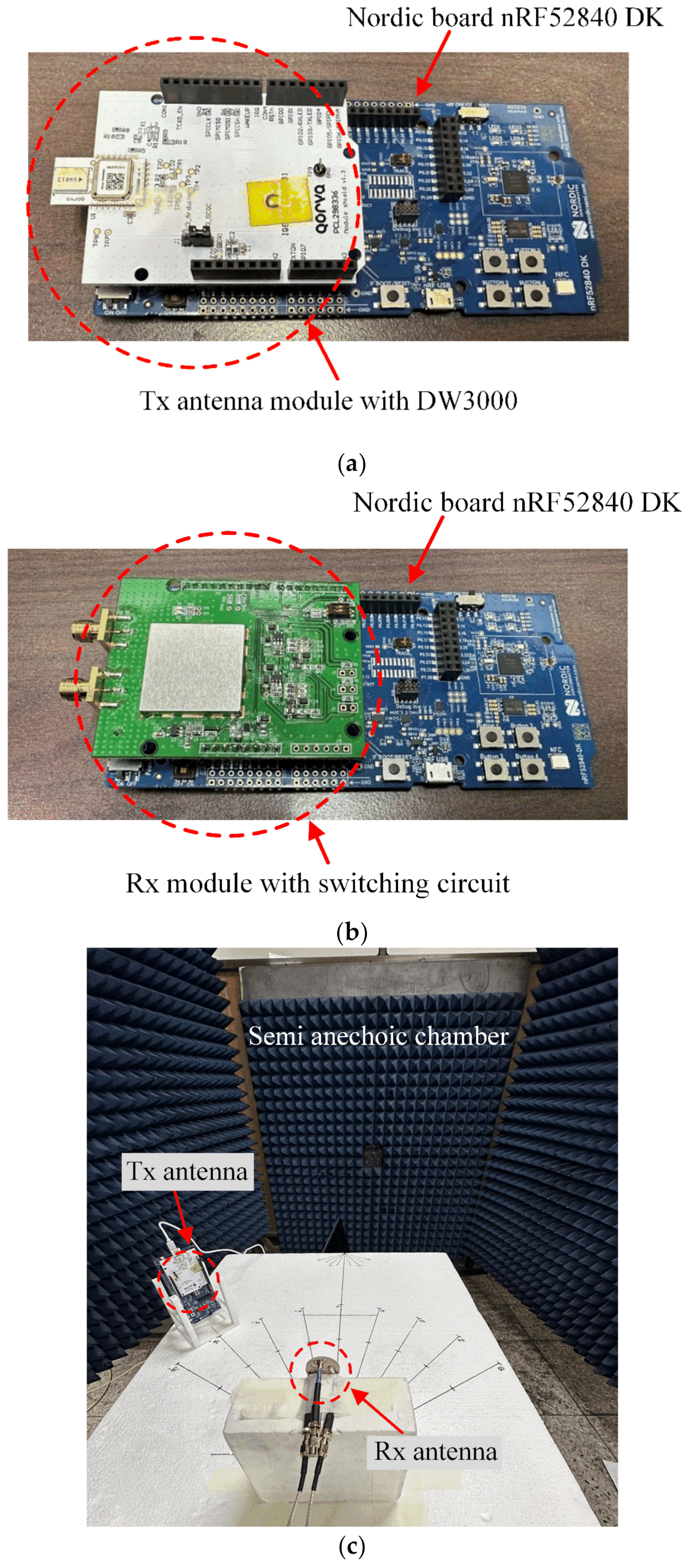
| Performance verification using commercial system | Qorvo’s DW3000 | - | - | - |
Disclaimer/Publisher’s Note: The statements, opinions and data contained in all publications are solely those of the individual author(s) and contributor(s) and not of MDPI and/or the editor(s). MDPI and/or the editor(s) disclaim responsibility for any injury to people or property resulting from any ideas, methods, instructions or products referred to in the content. |
© 2023 by the authors. Licensee MDPI, Basel, Switzerland. This article is an open access article distributed under the terms and conditions of the Creative Commons Attribution (CC BY) license (https://creativecommons.org/licenses/by/4.0/).
Share and Cite
Youn, S.; Ohm, S.; Jang, B.-J.; Choo, H. Design of a Tripod-Shaped Radiator Patch Antenna for Ultra-Wideband Direction Finding. Sensors 2023, 23, 9157. https://doi.org/10.3390/s23229157
Youn S, Ohm S, Jang B-J, Choo H. Design of a Tripod-Shaped Radiator Patch Antenna for Ultra-Wideband Direction Finding. Sensors. 2023; 23(22):9157. https://doi.org/10.3390/s23229157
Chicago/Turabian StyleYoun, Sangwoon, Sungsik Ohm, Byung-Jun Jang, and Hosung Choo. 2023. "Design of a Tripod-Shaped Radiator Patch Antenna for Ultra-Wideband Direction Finding" Sensors 23, no. 22: 9157. https://doi.org/10.3390/s23229157