

A New Assistance Navigation Method for Substation Inspection Robots to Safely Cross Grass Areas


Abstract
:1. Introduction
- (1)
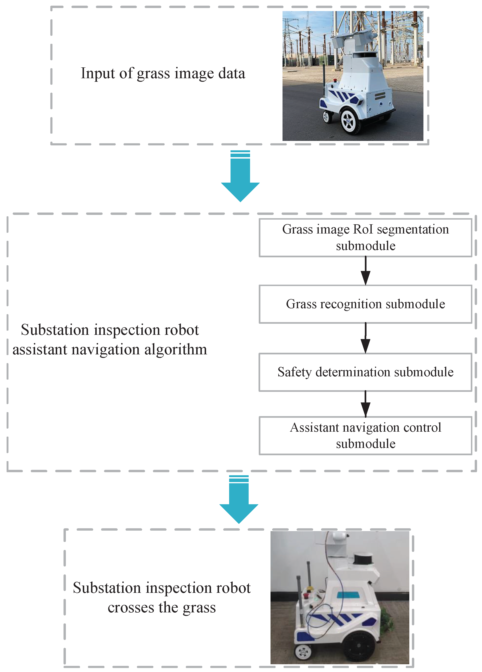
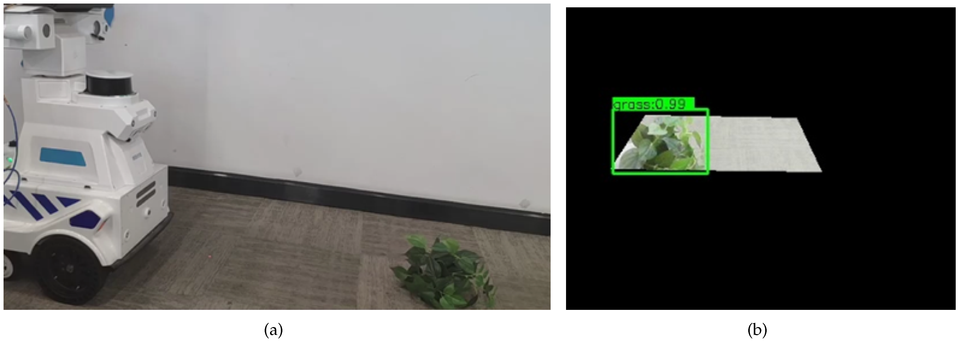
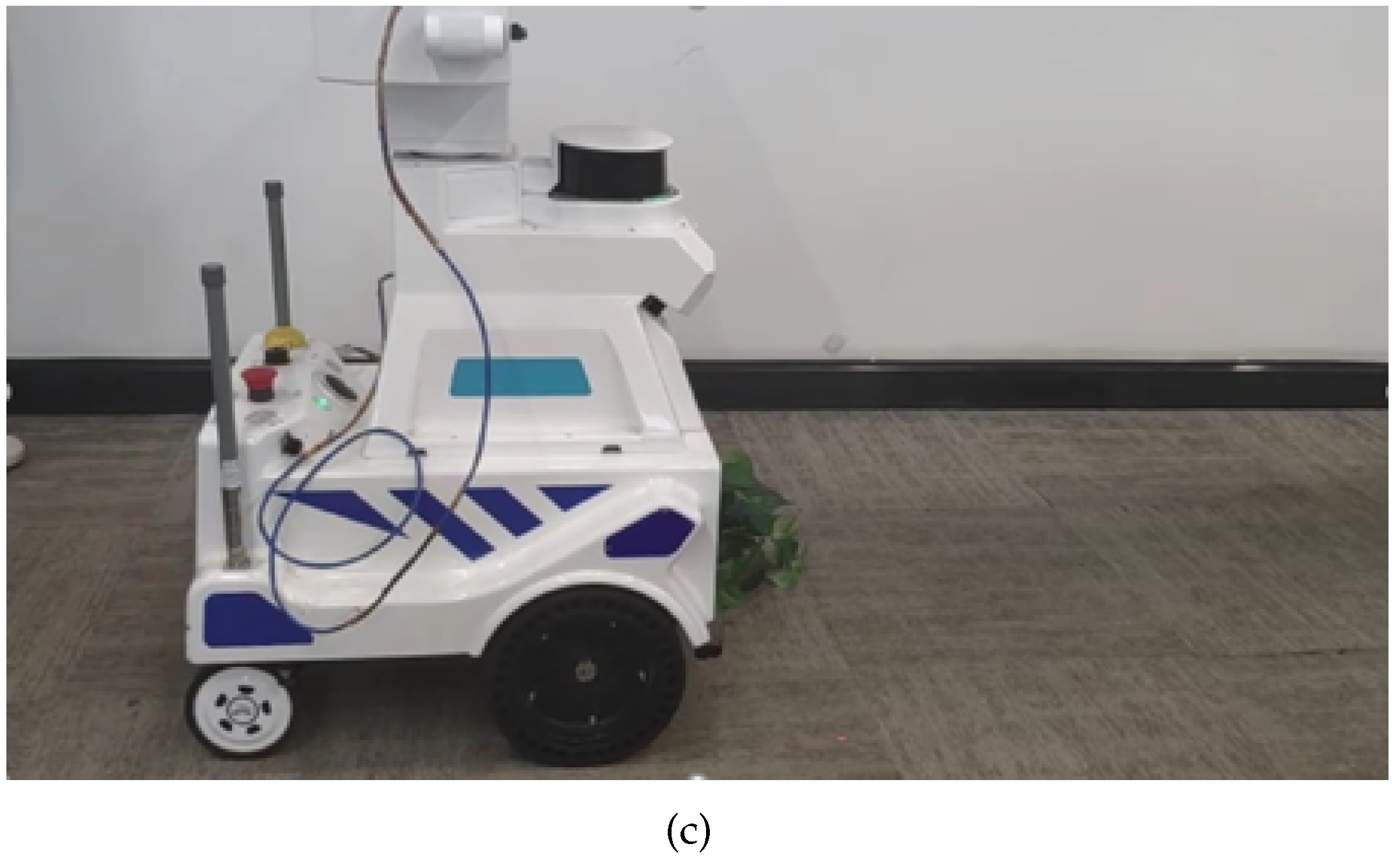
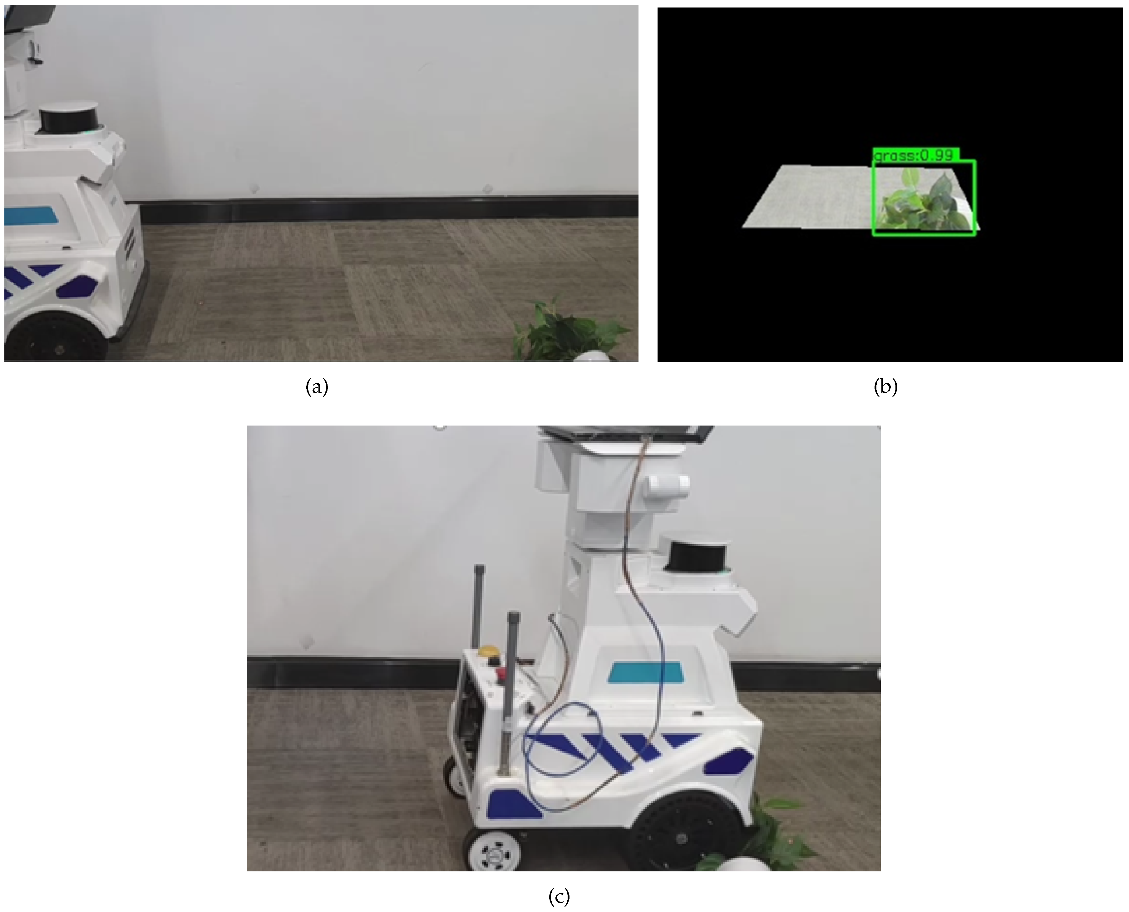
- An assistant navigation algorithm for substation inspection robots is designed to fuse ultrasonic radar signals with object recognition results and perform safety determination, which enables the inspection robots to cross the grass on routes of travel safely. The proposed assistant navigation algorithm is transplanted into the embedded platform, which can be effectively combined with the substation inspection robot.
- (2)
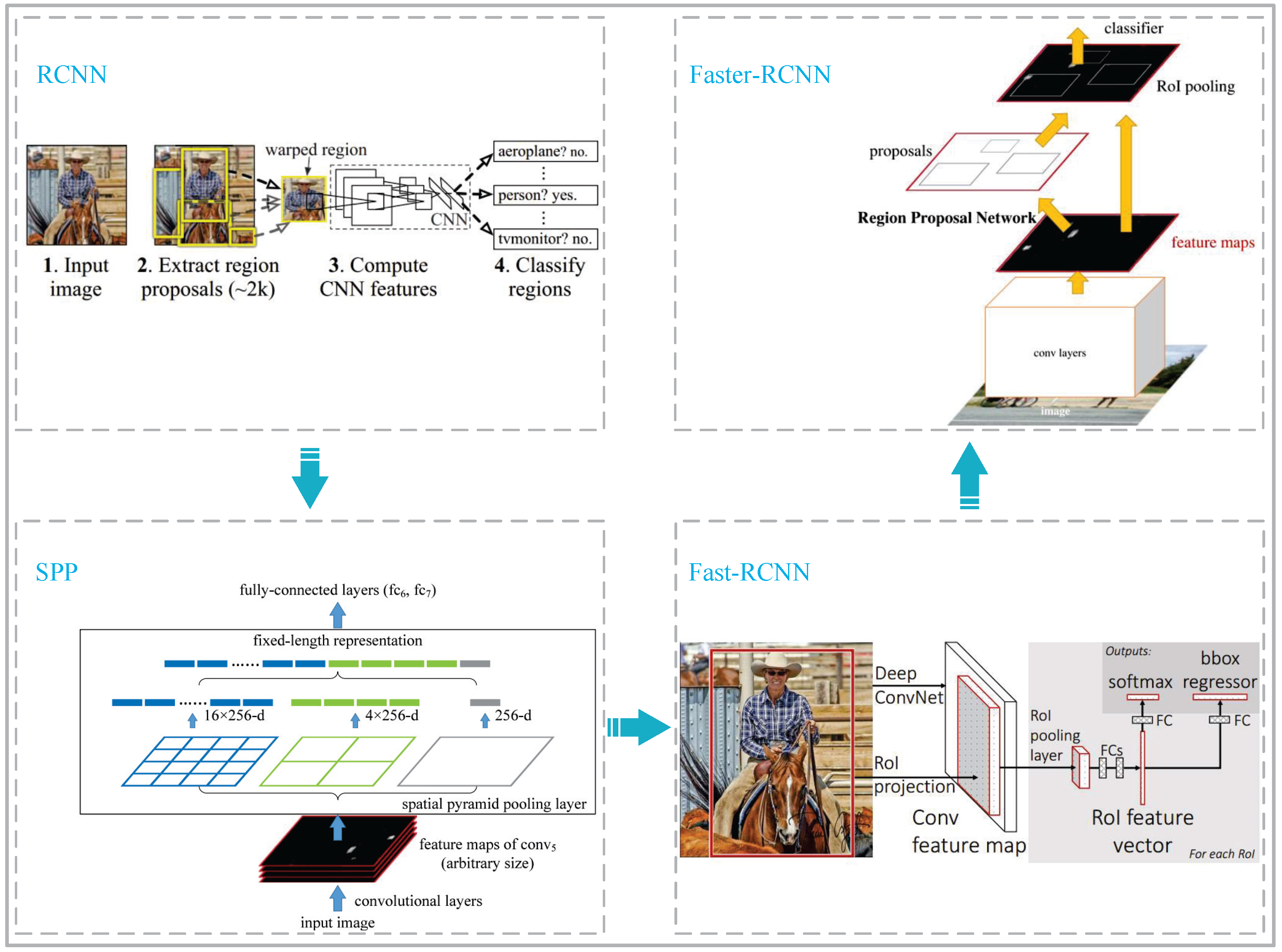
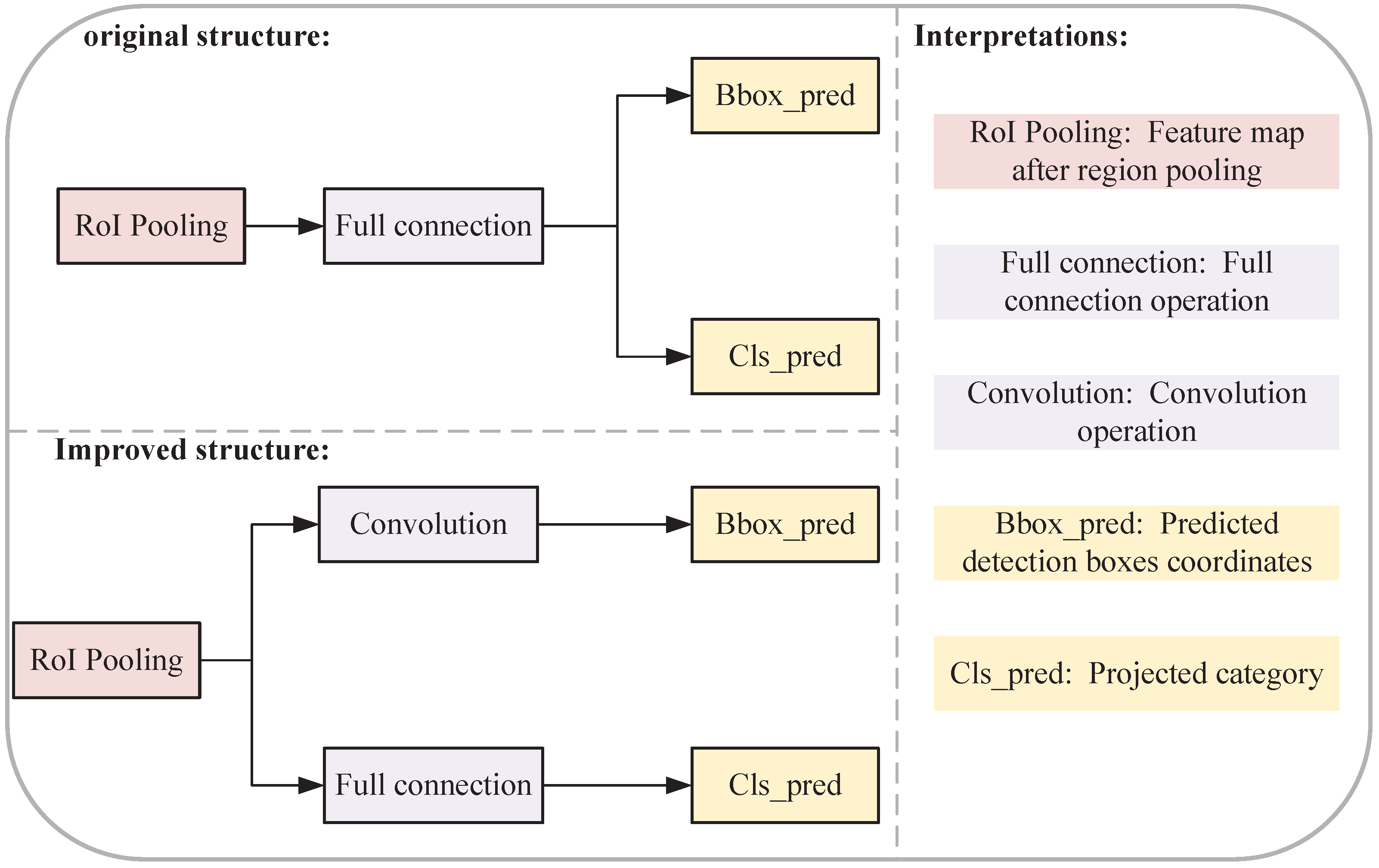
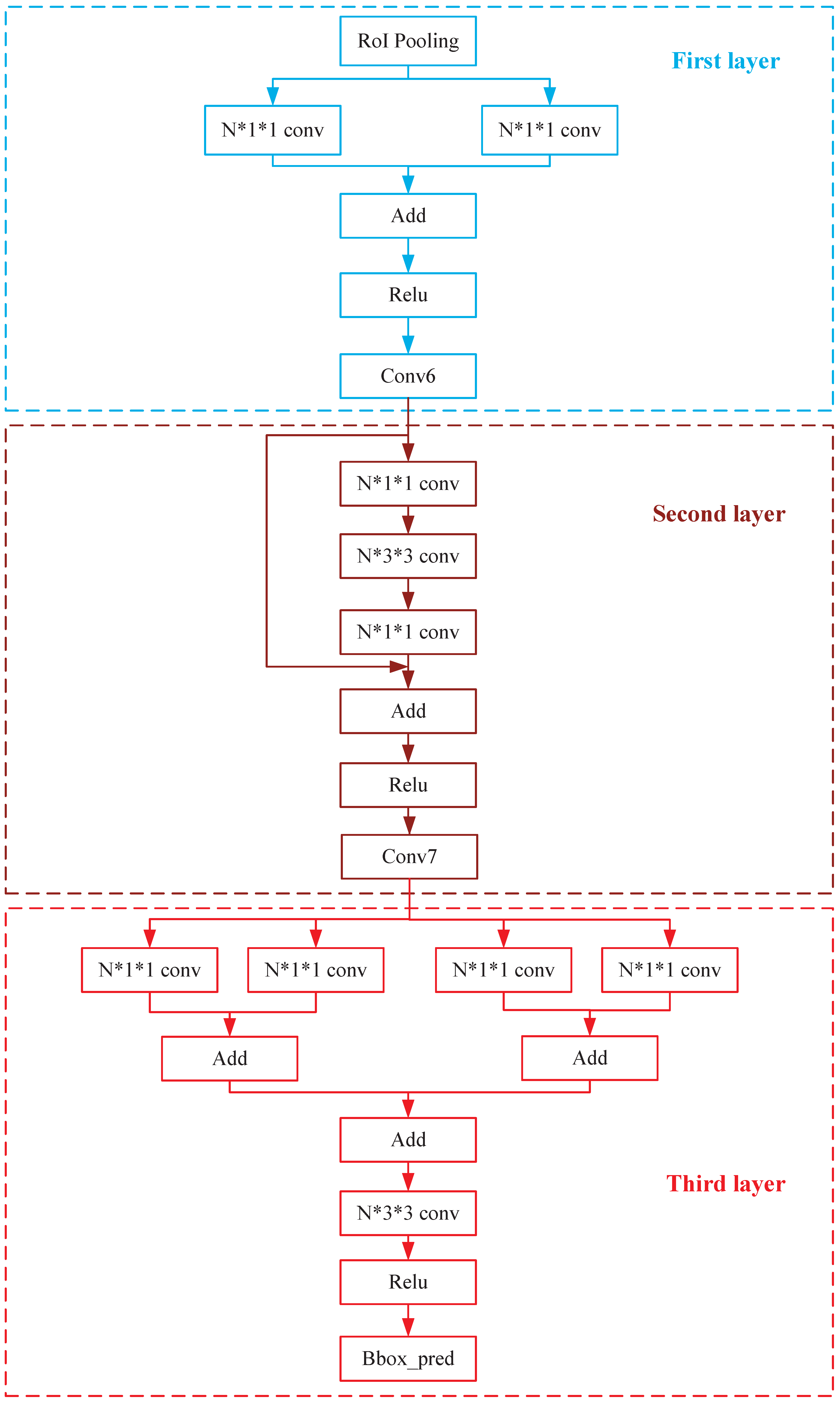
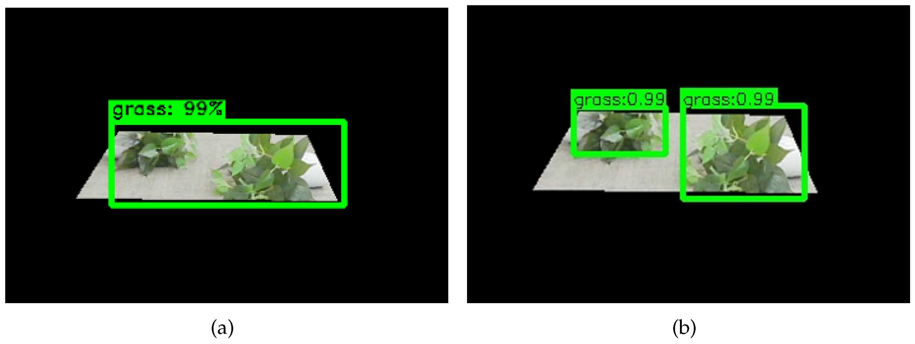
- In the assistant navigation algorithm, an improved Faster-RCNN-based network for recognizing the grass of substations is proposed in this paper, which designs a three-layer convolutional structure to replace the full connection structure to improve the accuracy of multiple object-detection boxes in grass images.
2. The Proposed Method of This Paper
- (1)
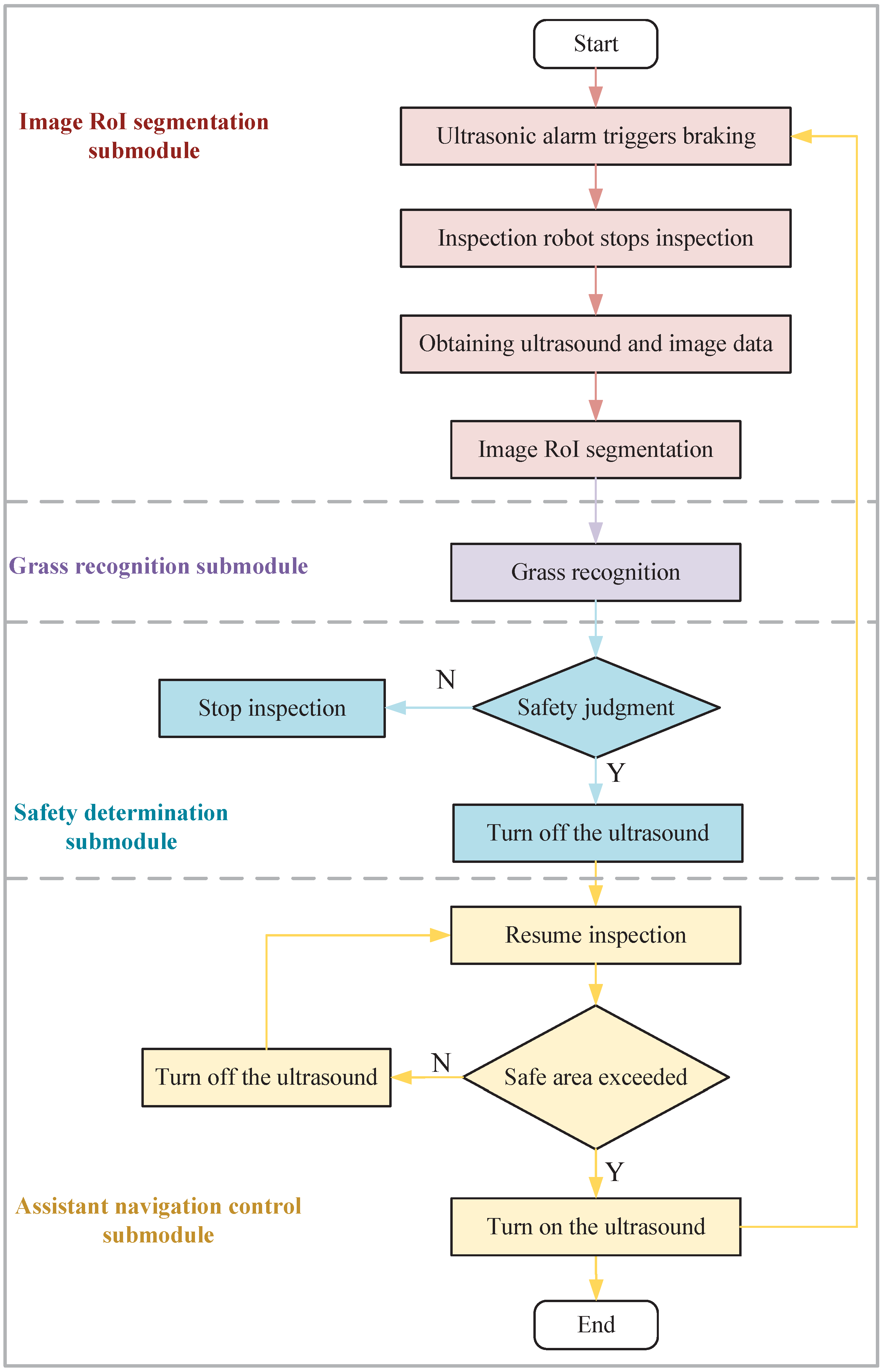
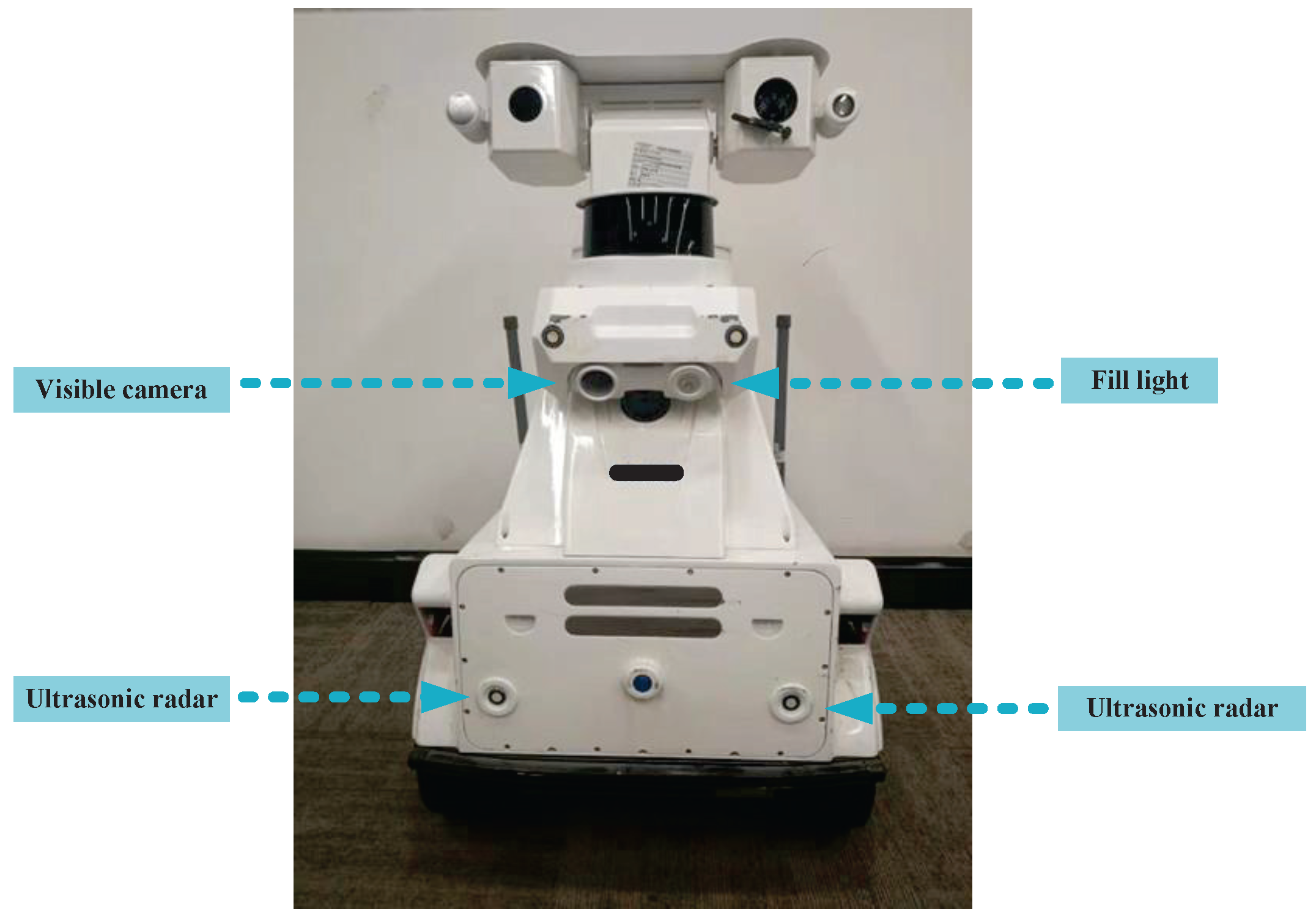
- Ultrasonic radar will trigger the inspection robot to brake when it detects an obstacle, and then, the robot will stop inspecting. The robot will stay in place and wait for the image RoI segmentation submodule of the auxiliary navigation algorithm to start working.
- (2)
- Collect ultrasonic radar data and image data and perform RoI segmentation on images based on ultrasonic radar data.
- (3)
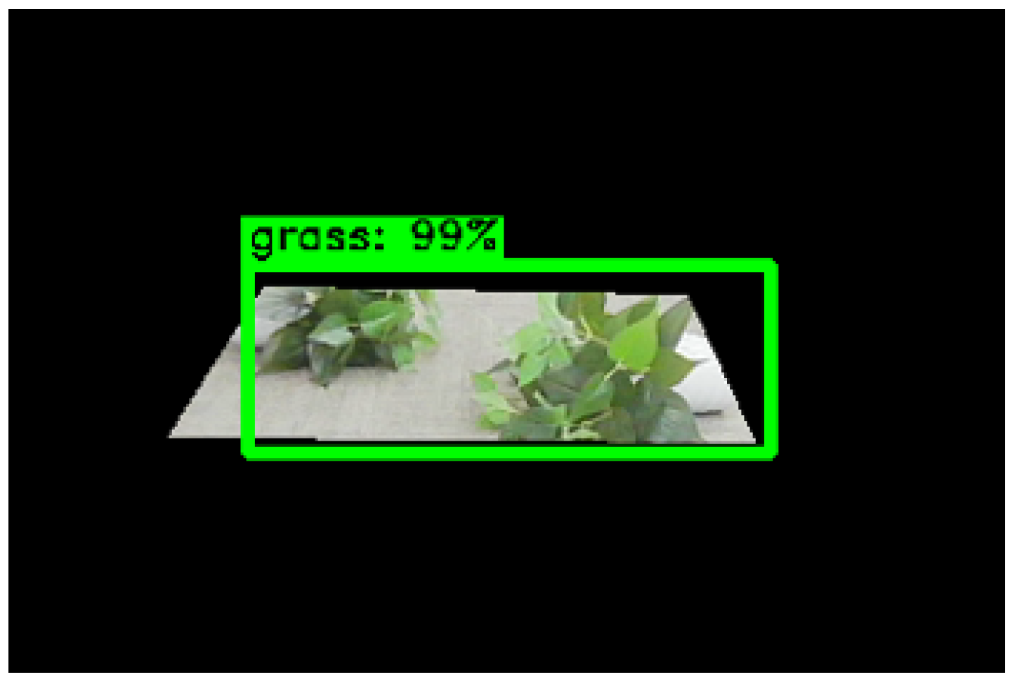
- Recognition of the segmented image is performed using the improved model to generate detection boxes and grass category information.
- (4)
- A safety decision method is used to determine the safety of the front of the route.
- (5)
- Receiving the determination that the area in front of the inspection robot is safe, ultrasonic radar is blocked, and the inspection robot continues to perform the inspection task. At the same time, the assistant navigation algorithm detects the mileage data, and if the moving distance exceeds the distance between the inspection robot and the grass obstacle, the shielding ultrasonic radar is canceled, and the assistant navigation algorithm is completed.
2.1. Grass Image RoI Segmentation Submodule
2.2. Grass Recognition Submodule
2.2.1. Development of RCNN
2.2.2. Improved Faster-RCNN Network Structure
2.3. Safety Determination and Assistant Navigation Control Submodules
3. Experimental Results and Analysis
3.1. Experiments Environment and Dataset
3.2. Experimental Data Preprocessing and Augmentation
3.3. Evaluation Criteria
- (1)
- mAPThe mAP calculation is shown in Equation (1).where P is accuracy, R is recall.
- (2)
- IoUThe calculation of IoU is shown in Equation (2).where Overlap denotes the area of the intersection of the two detection boxes; Union denotes the total area covered by the two detection boxes.
- (3)
- FPSThe calculation of FPS is shown in Equation (3).where FPS denotes the image frame rate that the network can infer per second.
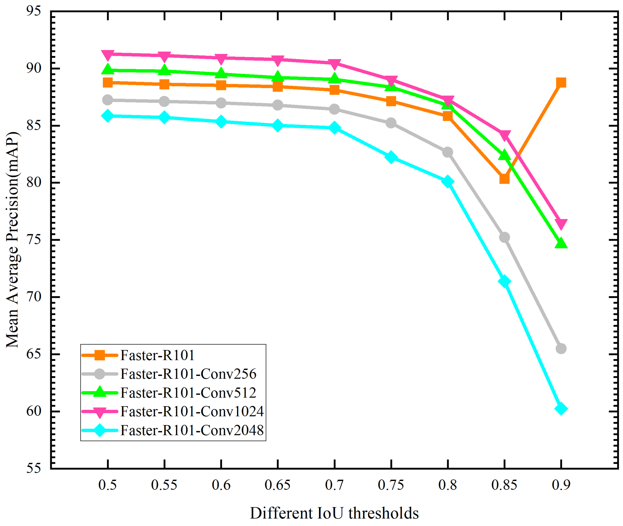
3.4. The Performance Validation of the Improved Network
3.5. The Implementation of Assistant Navigation Algorithm for Inspection Robots
4. Conclusions and Future Work
Author Contributions
Funding
Institutional Review Board Statement
Informed Consent Statement
Data Availability Statement
Acknowledgments
Conflicts of Interest
References
- Waleed, A.; Virk, U.S.; Riaz, M.T.; Mehmood, S.B.; Ahmad, S.; Javed, M.R.; Raza, A. Effectiveness and comparison of digital substations over conventional substations. Adv. Sci. Technol. Eng. Syst. 2019, 4, 431–439. [Google Scholar] [CrossRef]
- Zhao, B.; Lan, H.; Niu, Z.; Zhu, H.; Qian, T.; Tang, W. Detection and location of safety protective wear in power substation operation using wear-enhanced YOLOv3 Algorithm. IEEE Access 2021, 9, 125540–125549. [Google Scholar] [CrossRef]
- Zeynal, H.; Eidiani, M.; Yazdanpanah, D. Intelligent Substation Automation Systems for robust operation of smart grids. In Proceedings of the 2014 IEEE Innovative Smart Grid Technologies—Asia, Kuala Lumpur, Malaysia, 20–23 May 2014; pp. 786–790. [Google Scholar] [CrossRef]
- Wang, P.; Li, C.; Yang, Q.; Fu, L.; Yu, F.; Min, L.; Guo, D.; Li, X. Environment Understanding Algorithm for Substation Inspection Robot Based on Improved DeepLab V3+. J. Imaging 2022, 8, 257. [Google Scholar] [CrossRef] [PubMed]
- Pal, D.; Meyur, R.; Menon, S.; Reddy, M.J.B.; Mohanta, D.K. Real-time condition monitoring of substation equipment using thermal cameras. IET Gener. Transm. Distrib. 2018, 12, 895–902. [Google Scholar] [CrossRef]
- Huang, Q.; Jing, S.; Li, J.; Cai, D.; Wu, J.; Zhen, W. Smart Substation: State of the Art and Future Development. IEEE Trans. Power Deliv. 2017, 32, 1098–1105. [Google Scholar] [CrossRef]
- Lu, S.Y.; Zhang, Y.; Su, J.J. Mobile Robot for Power Substation Inspection: A Survey. IEEE/CAA J. Autom. Sin. 2017, 4, 830–847. [Google Scholar] [CrossRef]
- Lu, P.; Sun, W.; An, C.; Fu, Q.; Long, C.; Li, W. Slam and Navigation of Electric Power Intelligent Inspection Robot based on ROS. In Proceedings of the 2021 IEEE 2nd International Conference on Information Technology, Big Data and Artificial Intelligence, Nanchang, China, 26–28 March 2021; pp. 982–986. [Google Scholar] [CrossRef]
- Zhang, Y.; Zhou, Y.; Li, H.; Hao, H.; Chen, W.; Zhan, W. The Navigation System of a Logistics Inspection Robot Based on Multi-Sensor Fusion in a Complex Storage Environment. Sensors 2022, 22, 7794. [Google Scholar] [CrossRef]
- Hamuda, E.; Mc Ginley, B.; Glavin, M.; Jones, E. Automatic crop detection under field conditions using the HSV colour space and morphological operations. Comput. Electron. Agric. 2017, 133, 97–107. [Google Scholar] [CrossRef]
- Yang, C. Plant leaf recognition by integrating shape and texture features. Pattern Recognit. 2021, 112, 107809. [Google Scholar] [CrossRef]
- Hu, K.; Coleman, G.; Zeng, S.; Wang, Z.; Walsh, M. Graph weeds net: A graph-based deep learning method for weed recognition. Comput. Electron. Agric. 2020, 174, 105520. [Google Scholar] [CrossRef]
- Mahmudul Hasan, A.; Sohel, F.; Diepeveen, D.; Laga, H.; Jones, M.G.K. Weed recognition using deep learning techniques on class-imbalanced imagery. Crop Pasture Sci. 2023, 74, 628–644. [Google Scholar] [CrossRef]
- Xu, Y.; Zhai, Y.; Zhao, B.; Jiao, Y.; Kong, S.; Zhou, Y.; Gao, Z. Weed recognition for depthwise separable network based on transfer learning. Intell. Autom. Soft Comput. 2021, 27, 669–682. [Google Scholar] [CrossRef]
- Ding, H.; Junling, W.; Jing, W.; ZiYin, M.; Xu, Z.; DePeng, D. Study on Identification for the Typical Pasture Based on Image Texture Features. In Proceedings of the 2019 Chinese Control and Decision Conference (CCDC), Nanchang, China, 3–5 June 2019; pp. 778–782. [Google Scholar] [CrossRef]
- Dinc, S.; Parra, L.A.C. A three layer spatial-spectral hyperspectral image classification model using guided median filters. In Proceedings of the 2021 ACMSE Conference—ACMSE 2021: The Annual ACM Southeast Conference, Virtual, 15–17 April 2021; pp. 122–129. [Google Scholar] [CrossRef]
- Parra, L.; Marin, J.; Yousfi, S.; Rincón, G.; Mauri, P.V.; Lloret, J. Edge detection for weed recognition in lawns. Comput. Electron. Agric. 2020, 176, 105684. [Google Scholar] [CrossRef]
- Kounalakis, T.; Triantafyllidis, G.A.; Nalpantidis, L. Weed recognition framework for robotic precision farming. In Proceedings of the IST 2016—2016 IEEE International Conference on Imaging Systems and Techniques, Chania, Greece, 4–6 October 2016; pp. 466–471. [Google Scholar] [CrossRef]
- Michaels, A.; Haug, S.; Albert, A. Vision-based high-speed manipulation for robotic ultra-precise weed control. In Proceedings of the IEEE International Conference on Intelligent Robots and Systems, Hamburg, Germany, 28 September–3 October 2015; Volume 2015, pp. 5498–5505. [Google Scholar] [CrossRef]
- Rublee, E.; Rabaud, V.; Konolige, K.; Bradski, G. ORB: An efficient alternative to SIFT or SURF. In Proceedings of the 2011 International Conference on Computer Vision, Barcelona, Spain, 6–13 November 2011; pp. 2564–2571. [Google Scholar]
- Lin, G.; Zhenzhong, L.; Qiufeng, W.; Lulu, W. Multi-type feature fusion technique for weed identification in cotton fields. Int. J. Signal Process. Image Process. Pattern Recognit. 2016, 9, 355–368. [Google Scholar] [CrossRef]
- Zheng, Z.; Hu, Y.; Guo, T.; Qiao, Y.; He, Y.; Zhang, Y.; Huang, Y. AGHRNet: An attention ghost-HRNet for confirmation of catch-and-shake locations in jujube fruits vibration harvesting. Comput. Electron. Agric. 2023, 210, 107921. [Google Scholar] [CrossRef]
- Zheng, Z.; Hu, Y.; Yang, H.; Qiao, Y.; He, Y.; Zhang, Y.; Huang, Y. AFFU-Net: Attention feature fusion U-Net with hybrid loss for winter jujube crack detection. Comput. Electron. Agric. 2022, 198, 107049. [Google Scholar] [CrossRef]
- Zhao, M.; Liu, Q.; Jha, A.; Deng, R.; Yao, T.; Mahadevan-Jansen, A.; Tyska, M.J.; Millis, B.A.; Huo, Y. VoxelEmbed: 3D Instance Segmentation and Tracking with Voxel Embedding based Deep Learning. In Machine Learning in Medical Imaging; Lian, C., Cao, X., Rekik, I., Xu, X., Yan, P., Eds.; Lecture Notes in Computer Science (Including Subseries Lecture Notes in Artificial Intelligence and Lecture Notes in Bioinformatics); Springer: Cham, Switzerland, 2021; Volume 12966 LNCS, pp. 437–446. [Google Scholar] [CrossRef]
- dos Santos Ferreira, A.; Matte Freitas, D.; Gonçalves da Silva, G.; Pistori, H.; Theophilo Folhes, M. Weed detection in soybean crops using ConvNets. Comput. Electron. Agric. 2017, 143, 314–324. [Google Scholar] [CrossRef]
- Hasan, A.S.M.M.; Sohel, F.; Diepeveen, D.; Laga, H.; Jones, M.G. A survey of deep learning techniques for weed detection from images. Comput. Electron. Agric. 2021, 184, 106067. [Google Scholar] [CrossRef]
- Jiang, H.; Zhang, C.; Qiao, Y.; Zhang, Z.; Zhang, W.; Song, C. CNN feature based graph convolutional network for weed and crop recognition in smart farming. Comput. Electron. Agric. 2020, 174, 105450. [Google Scholar] [CrossRef]
- Tao, T.; Wei, X. A hybrid CNN–SVM classifier for weed recognition in winter rape field. Plant Methods 2022, 18, 29. [Google Scholar] [CrossRef]
- Ayhan, B.; Kwan, C. Tree, Shrub, and Grass Classification Using Only RGB Images. Remote Sens. 2020, 12, 1333. [Google Scholar] [CrossRef]
- Olaniyi, O.M.; Daniya, E.; Abdullahi, I.M.; Bala, J.A.; Olanrewaju, E.A. Weed recognition system for low-land rice precision farming using deep learning approach. In Artificial Intelligence and Industrial Applications: Smart Operation Management; Springer: Cham, Switzerland, 2021; pp. 385–402. [Google Scholar]
- Chen, J.; Wang, H.; Zhang, H.; Luo, T.; Wei, D.; Long, T.; Wang, Z. Weed detection in sesame fields using a YOLO model with an enhanced attention mechanism and feature fusion. Comput. Electron. Agric. 2022, 202, 107412. [Google Scholar] [CrossRef]
- He, K.; Zhang, X.; Ren, S.; Sun, J. Deep residual learning for image recognition. In Proceedings of the IEEE Computer Society Conference on Computer Vision and Pattern Recognition, Las Vegas, NV, USA, 27–30 June 2016; Volume 2016, pp. 770–778. [Google Scholar] [CrossRef]
- Girshick, R.; Donahue, J.; Darrell, T.; Malik, J. Rich feature hierarchies for accurate object detection and semantic segmentation. In Proceedings of the IEEE Computer Society Conference on Computer Vision and Pattern Recognition, Columbus, OH, USA, 23–28 June 2014; pp. 580–587. [Google Scholar] [CrossRef]
- He, K.; Zhang, X.; Ren, S.; Sun, J. Spatial Pyramid Pooling in Deep Convolutional Networks for Visual Recognition. IEEE Trans. Pattern Anal. Mach. Intell. 2015, 37, 1904–1916. [Google Scholar] [CrossRef] [PubMed]
- Girshick, R. Fast R-CNN. In Proceedings of the IEEE International Conference on Computer Vision, Santiago, Chile, 7–13 December 2015; Volume 2015, pp. 1440–1448. [Google Scholar] [CrossRef]
- Ren, S.; He, K.; Girshick, R.; Sun, J. Faster R-CNN: Towards real-time object detection with region proposal networks. In Proceedings of the 28th International Conference on Neural Information Processing Systems (NIPS 2015), Montreal, QC, Canada, 7–12 December 2015; Volume 2015, pp. 91–99. [Google Scholar]
- Thanh Le, V.N.; Truong, G.; Alameh, K. Detecting weeds from crops under complex field environments based on Faster RCNN. In Proceedings of the 2020 IEEE Eighth International Conference on Communications and Electronics (ICCE), Phu Quoc Island, Vietnam, 13–15 January 2021; pp. 350–355. [Google Scholar] [CrossRef]
- Chang, C.L.; Chung, S.C. Improved Deep Learning-based Approach for Real-time Plant Species Recognition on the Farm. In Proceedings of the 2020 12th International Symposium on Communication Systems, Networks and Digital Signal Processing (CSNDSP), Porto, Portugal, 20–22 July 2020; pp. 1–5. [Google Scholar] [CrossRef]


| Total | Training Set | Test Set | |
|---|---|---|---|
| Original data | 528 | 469 | 59 |
| Data augmentation | 3600 | 3240 | 360 |
| Networks | Feature Extraction Network | mAP (%) | FPS (frame/s) |
|---|---|---|---|
| SSD | ResNet101 | 76.7 | 10 |
| YOLO | ResNet101 | 63.4 | 18 |
| Faster-RCNN | ResNet101 | 81.32 | 1 |
| Networks | Convolution Kernel Dimension | Learning Rate | Number of Iterations | mAP (%) |
|---|---|---|---|---|
| Faster-R101 (basic) | / | 0.0001 | 50 | 88.41 |
| Faster-R101-Conv256 | 256 | 0.0001 | 50 | 86.24 |
| Faster-R101-Conv512 | 512 | 0.0001 | 50 | 90.60 |
| Faster-R101-Conv1024 | 1024 | 0.0001 | 50 | 92.54 |
| Faster-R101-Conv2048 | 2048 | 0.0001 | 50 | 84.26 |
| Networks | Different IoU Thresholds | ||||||||
|---|---|---|---|---|---|---|---|---|---|
| 0.5 | 0.55 | 0.6 | 0.65 | 0.7 | 0.75 | 0.8 | 0.85 | 0.9 | |
| mAP (%) | |||||||||
| Faster-R101 (basic) | 88.76 | 88.61 | 88.53 | 88.40 | 88.12 | 87.13 | 85.83 | 80.34 | 88.76 |
| Faster-R101-Conv256 | 87.23 | 87.11 | 86.97 | 86.78 | 86.43 | 85.22 | 82.67 | 75.21 | 65.49 |
| Faster-R101-Conv512 | 89.83 | 89.74 | 89.49 | 89.20 | 89.03 | 88.37 | 86.78 | 82.34 | 74.63 |
| Faster-R101-Conv1024 | 91.25 | 91.13 | 90.92 | 90.78 | 90.46 | 89.01 | 87.27 | 84.25 | 76.47 |
| Faster-R101-Conv2048 | 85.86 | 85.72 | 85.34 | 85.02 | 84.81 | 82.24 | 80.12 | 71.38 | 60.25 |
Disclaimer/Publisher’s Note: The statements, opinions and data contained in all publications are solely those of the individual author(s) and contributor(s) and not of MDPI and/or the editor(s). MDPI and/or the editor(s) disclaim responsibility for any injury to people or property resulting from any ideas, methods, instructions or products referred to in the content. |
© 2023 by the authors. Licensee MDPI, Basel, Switzerland. This article is an open access article distributed under the terms and conditions of the Creative Commons Attribution (CC BY) license (https://creativecommons.org/licenses/by/4.0/).
Share and Cite
Yang, Q.; Ma, S.; Zhang, G.; Xian, K.; Zhang, L.; Dai, Z. A New Assistance Navigation Method for Substation Inspection Robots to Safely Cross Grass Areas. Sensors 2023, 23, 9201. https://doi.org/10.3390/s23229201
Yang Q, Ma S, Zhang G, Xian K, Zhang L, Dai Z. A New Assistance Navigation Method for Substation Inspection Robots to Safely Cross Grass Areas. Sensors. 2023; 23(22):9201. https://doi.org/10.3390/s23229201
Chicago/Turabian StyleYang, Qiang, Song Ma, Gexiang Zhang, Kaiyi Xian, Lijia Zhang, and Zhongyu Dai. 2023. "A New Assistance Navigation Method for Substation Inspection Robots to Safely Cross Grass Areas" Sensors 23, no. 22: 9201. https://doi.org/10.3390/s23229201
APA StyleYang, Q., Ma, S., Zhang, G., Xian, K., Zhang, L., & Dai, Z. (2023). A New Assistance Navigation Method for Substation Inspection Robots to Safely Cross Grass Areas. Sensors, 23(22), 9201. https://doi.org/10.3390/s23229201