2. Related Work
We review existing 3D-HPE methods at varying degrees of supervision.
The full supervision of deep learning models involves direct optimization by comparing their predicted output to the expected ground truth. Pose estimation methods in this category learn a mapping from 2D to 3D poses by supervising pairs of 2D–3D correspondence. Fully supervised multi-view 3D pose estimators [
7,
8,
9,
10,
11] lead pose estimation accuracy with 17.6 mm mean per-joint position error (MPJPE) state-of-the-art performance on H36M [
12]. However, most real-world scenarios are restricted to a single viewpoint. This motivates the study of monocular (single-view) 3D human pose estimation. The leading monocular 3D-HPE networks are trained with full supervision [
13,
14,
15,
16,
17,
18] and have obtained a mean joint position error as low as 21.6 mm on the H36M dataset. We believe that more training data with richer variety is key to bridging the performance gap between monocular and multi-view 3D-HPE. However, curating a large dataset with a rich variety of persons, activities, and scenery is difficult to accomplish because of the non-trivial setup of motion capture systems used to generate 3D pose annotations. As an alternative, some works have proposed the use of additional synthetic training data generated by stitching together image patches [
19,
20,
21] or poses [
22], using graphics engines [
23,
24], or directly augmenting 2D and 3D pose pairs via a jointly trained GAN that learns to generate realistic 3D poses [
25,
26,
27]. Other works have explored weakly and semi-supervised 3D-HPE to distill knowledge from large amounts of unlabeled data and leverage its rich pose variety.
The concept of the weak or self-supervision of deep neural networks involves the implicit optimization of a model either without the knowledge of the expected output or without a direct comparison between each predicted output and the corresponding ground-truth target. The appeal of studying self- or weakly supervised deep learning techniques is the lower reliance on the availability of structured annotated training data, as they can be difficult to obtain in large amounts for some deep learning problems. Pose estimation works in this category include methods designed to train pose estimators without 3D pose annotations [
28,
29,
30,
31] or use 3D pose annotations to train a network without one-to-one correspondence between input 2D images or poses and the target 3D pose annotations [
32,
33]. Zhou et al. [
33] augmented a 2D pose estimator with a depth regression sub-network and jointly trained both sub-nets with 2D and 3D labels to fully exploit the correlation between 2D pose and depth estimation sub-tasks. Other works like [
34] looked to exploit multi-view information only during training. Hua et al. [
35] proposed a U-shaped cross-view graph convolution network (GCN) that was trained without 3D labels. Instead, a triangulation and refinement procedure was performed across two views to lift 2D keypoints into coarse 3D poses. Iqbal et al. [
36] presented a weakly supervised framework that optimized multi-view consistency. Given 2D images, their network estimated 2.5D poses (2D joint heat maps and depth maps) from which scale-normalized 3D poses were reconstructed. However, unlike our method, their multi-view consistency loss relied on a non-differentiable rigid alignment procedure and intrinsic camera parameters. Wandt et al. (CanonPose) [
37] proposed a self-supervised method that exploited the multi-view constraint by projecting the estimated 3D pose in one view to a 2D pose in another view and optimizing juxtaposed reprojected 2D losses. The following self-supervised works proposed different strategies for acquiring 3D pose annotations from multi-view 2D data. Gholami et al. (TriPose) [
38] triangulated a 3D pose given 2D poses from multiple views and estimated the relative orientation of poses. The triangulated 3D poses were then used as pseudo-annotations to train their 2D–3D pose lifting network. Kocabas et al. (EpipolarPose) [
39] presented a self-supervised method that utilized Epipolar geometry to obtain person and camera 3D poses from multi-view 2D images that were used as pseudo-labels to train their pose network.
Semi-supervised deep learning techniques look to leverage the advantages of full and weak supervision by training a model on a structured subset of annotated data and a larger subset of unlabeled data rich in variety. Thus, the model converges faster to a stable optimum because of the full supervision while attaining generalizability robustness thanks to the improved distribution of unlabeled data used in weak supervision. This category of 3D-HPE works tries to learn more robust 3D pose estimators by combining annotated 3D pose training data with much more unlabeled video data. Existing works [
40,
41,
42] have employed a dual-branch training pipeline with a fully supervised branch and a self-supervised branch that learns from the 2D pose inputs without 3D pose annotations. Rhodin et al. [
43] proposed addressing the problem of insufficiently large training samples by learning a latent representation of 3D geometry from multi-view 2D images. Wang et al. [
44] trained a 3D pose estimator by distilling knowledge from a modified non-rigid structure from motion (NRSfM) network used to reconstruct 3D shapes and camera positions from multiple 2D poses. To reduce over-reliance on the reprojected 2D loss, some works have employed adversarial networks that learn a distribution of realistic poses [
25,
45]. Gong et al. [
25] presented an auto-augmentation GAN framework that learned to generate realistic 2D–3D poses, thereby increasing the quantity and diversity of supervised training data. Other works have focused on enforcing kinematic and pose geometry constraints on semi-supervised 3D pose encodings [
33,
46,
47,
48,
49]. Amadi and Agam [
6] proposed two effective biomechanical pose prior regularizers—bone proportion and joint mobility constraints—introduced to the weakly supervised branch to regulate overfitting to the 2D reprojection loss and directly optimize plausible 3D poses.
Naively enforcing multi-view consistency can lead to degenerated solutions. For example, triangulating 3D poses from estimated multi-view 2D poses using bundle adjustment may produce inaccurate results, especially when employing estimated camera parameters. Consequently, supervising the network with sub-optimal triangulated 3D poses may adversely affect performance. Previous works either used partial 3D annotation [
50], learned a multi-view latent embedding of 3D poses [
51], proposed a 2.5D approach to constrain the solution space [
36], or used multi-view projection loss [
37]. Iqbal et al. [
36] used Procrustes analysis to derive a rotation matrix that aligns reconstructed multi-view 3D poses before computing the joint position error loss. However, Procrustes alignment is non-differentiable because it involves singular-value decomposition. Therefore, the crucial computation of the rotation matrix must be detached from the network’s computation graph. This implies that the network cannot backpropagate through the derivation of the rotation matrix, which directly influences the loss being optimized. Unlike Iqbal et al., our proposed method is end-to-end because our posture loss uses a novel differentiable bone orientation alignment. This allows the resulting loss to be backpropagated through the alignment protocol, thereby maximizing network optimization at each training iteration. Our work falls under the category of monocular semi-supervised 3D-HPE. Our proposed multi-view posture consistency loss is a soft constraint that teaches the network to learn consistent 3D pose encoding across multiple viewpoints. We propose a framework that optimizes multi-view pose and posture consistency without 2D and 3D pose annotations for the majority of training data while utilizing biomechanical pose regularization techniques [
6] to constrain the 3D pose geometric properties. We also present a modified semi-supervised framework that does not require camera parameters.
3. Method
Reconstructed 3D pose error is typically the main optimization objective of pose estimation networks. Most pose models learn by minimizing the L2-norm between joints or the mean per-joint position error (MPJPE), which computes the Euclidean distance between estimated and ground-truth joints after aligning the root joints (typically the pelvis) of both poses. The L2-norm optimizes the 3D pose and location in space with respect to the observing camera, while the MPJPE optimizes the 3D pose irrespective of global placement. We decouple a 3D pose into global placement, orientation, and 3D posture, where posture captures the positioning of each joint relative to other joints, and independent of the camera bearings. Hence, posture is invariant to the global placement and orientation of the pose with respect to the observing camera. By extracting posture from pose we can analyze the structural correctness of 3D poses beyond the confines of the camera position and orientation. This becomes especially useful when exploiting multi-view information to train pose estimators without 3D joint and camera parameter annotations.
In the following sections, we first review the concept of 3D pose prior regularization adopted from an existing work to constrain the biomechanical properties of estimated 3D poses. We then describe the bone alignment procedure that is critical to extracting posture and is unaffected by the positioning, scale, and orientation of 3D poses in
Section 3.2. We then formulate the posture loss (
Section 3.3) and evaluation metrics (
Section 3.4) and elaborate on the peculiar attributes that distinguish them from existing pose estimation objectives and evaluation protocols. We describe the semi-supervised schemes used to train pose estimator networks, first with camera parameters (
Section 3.3.1) and then without camera parameters (
Section 3.3.2). The resulting performance of these configurations is discussed in
Section 4.
3.1. Biomechanical Pose Prior Regularization
This work builds upon our existing work on modeling the innate bone proportion and joint mobility properties of 3D human poses and constraining these biomechanical properties when training a weakly supervised 3D pose estimation network. The semi-supervised frameworks we propose in this work are bootstrapped by the biomechanical pose prior regularizers introduced by Amadi and Agam [
6]. Here, we briefly summarize the pose prior regularizers but refer the reader to the cited work for more details.
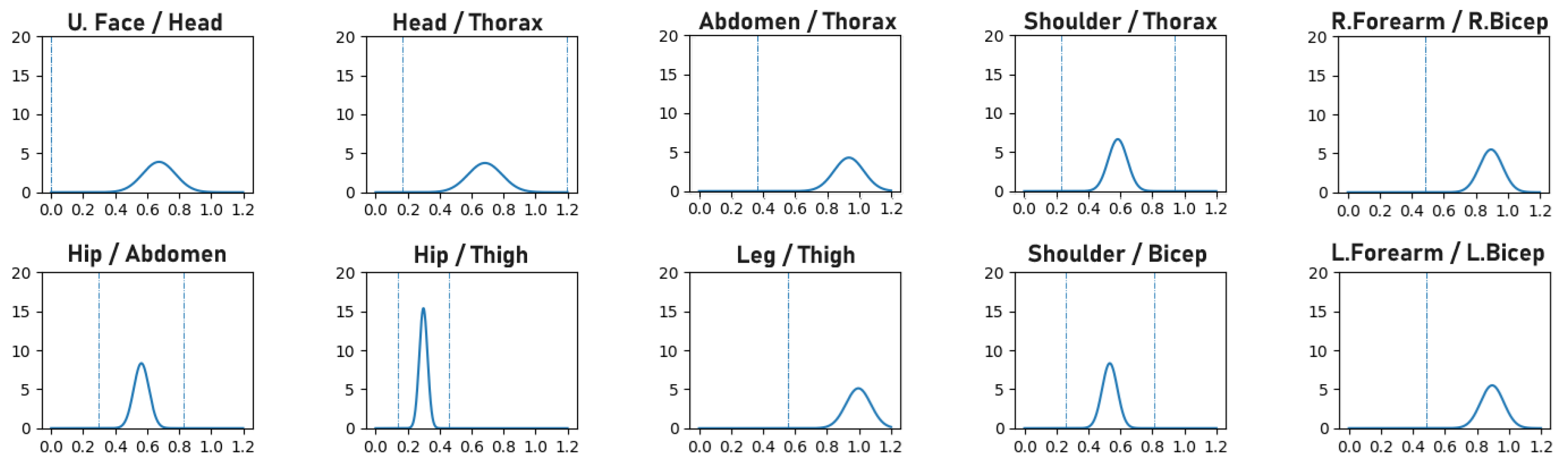
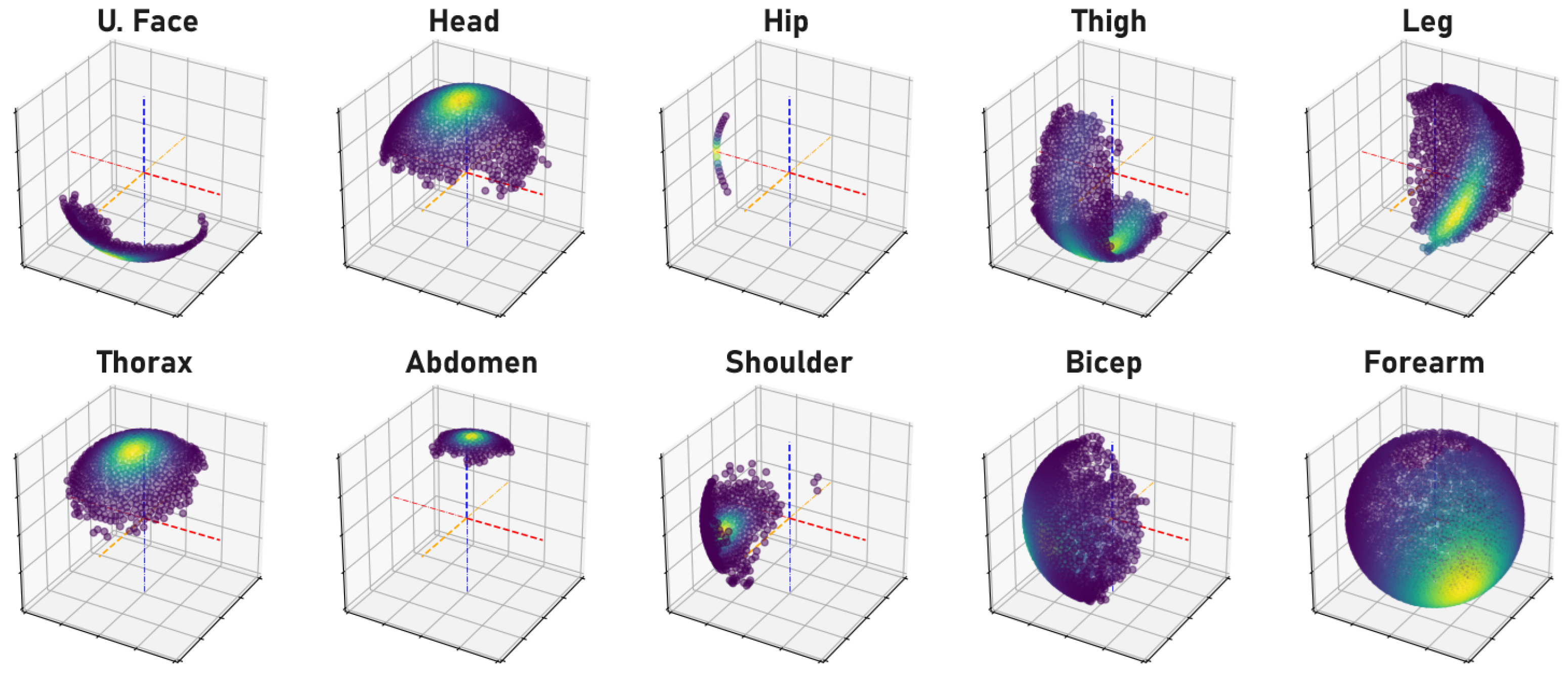
Human bone proportions and joint rotations are modeled by observing the annotated 3D pose training data of the H36M dataset to compute the mean and variance of the probability density functions (PDFs) that model the likelihood of bone proportions and orientations, as illustrated in
Figure 1 and
Figure 2, respectively. When training a network, the precomputed PDFs are used to assess the likelihood of the bone proportions and orientations of an estimated 3D pose. The model learns better pose estimation by maximizing the log-likelihood of bone proportions and joint rotations. By maximizing the log-likelihood of these biomechanical properties, the network is forced to encode more correct 3D poses.
3.2. Differentiable Bone Orientation Alignment
The objective of the proposed bone alignment procedure is to transform components of 3D poses in a standardized manner that facilitates the retrieval of the true orientation of each bone. The goal is to extract the orientation of each bone relative to other neighboring bones, irrespective of the size, global positioning, and general orientation of the 3D poses. This is achieved by selecting a set of four joints in close proximity to each other to guide the alignment of a bone. We start with the
Pivot and
Free keypoints, which are the joints at either end of the bone whose true orientation we want to extract. The other two joints are the
Axis and
Anchor keypoints. The Axis keypoint forms the
Axis-Bone with the Pivot keypoint, and the Pivot, Axis, and Anchor keypoints define a distinct plane that we refer to as the
Anchor-Plane. The purpose of the alignment procedure is to align the Anchor plane to the Cartesian XY-Plane with the Pivot keypoint at the origin and the Axis-Bone aligned with the X (or Y) axis. The outcome of this transformation is that the orientation of the Free-Bone is normalized with respect to the Axis and Anchor keypoints in a way that is invariant to the translation and rotation of the entire 3D pose. We ensure invariance to scale by extracting the Free-Bone’s unit vector after alignment. This alignment transformation is carried out for each bone with their corresponding, hand-selected, quadruplet keypoints. The procedure is illustrated for clarity in
Figure 3 with the example of right elbow alignment and described mathematically below.
Given each set of quadruplet keypoints
of a 3D pose
P, the goal is to align the Pivot, Axis, and Anchor keypoints with the XY-Plane. Note that
contains the 3D coordinates of the Free, Pivot, Axis, and Anchor keypoints, respectively. We first translate
so that the Pivot keypoint
moves to the Cartesian origin.
Next, we build a rotation matrix
to rotate the Free-Bone vector. The unit vectors corresponding to the X-, Y-, and Z-axis of the rotation matrix are derived below.
where
changes the direction of the unit vector. Note that the order of the cross products in Equations (2) and (3) and the choice of
and
for each bone alignment are guided by the right-hand rule and the relative positioning of the quadruplet keypoints with respect to the structure of a standard skeletal pose. The selected configurations for all 16 bones are provided in the Supplementary Materials. The intuition behind the derivation of the rotation matrix is that the Axis-Bone defines the direction of the new X- (or Y-) axis. The normal vector to the Anchor-Plane is the direction of the new Z-axis and the orthogonal vector between the new Z-axis, and the Axis-Bone defines the direction of the new Y- (or X-) axis. Note that the Axis-Bone may be horizontally aligned with the X-axis or vertically aligned with the Y-axis, depending on the Free-Bone. When horizontally aligned, the superscripts
a =
i and
c =
j in Equations (3) and (4) (i.e.,
=
,
=
). Otherwise, when vertically aligned,
c =
i and
a =
j (i.e.,
=
,
=
). Finally, the orientation of the Free-Bone
is extracted after rotation alignment in Equation (
5).
and
are the homogeneous and
components of the rotated bone, respectively.
This alignment procedure can be implemented such that the computations are vectorized as tensor operations and executed at once for all poses and bones in a batch. This makes it a fast and memory-efficient procedure. Our preset configurations for executing bone orientation alignment for each bone and the resulting 3D pose transformation effect are presented in
Appendix B.
3.3. Bone Orientation Error for Posture Loss
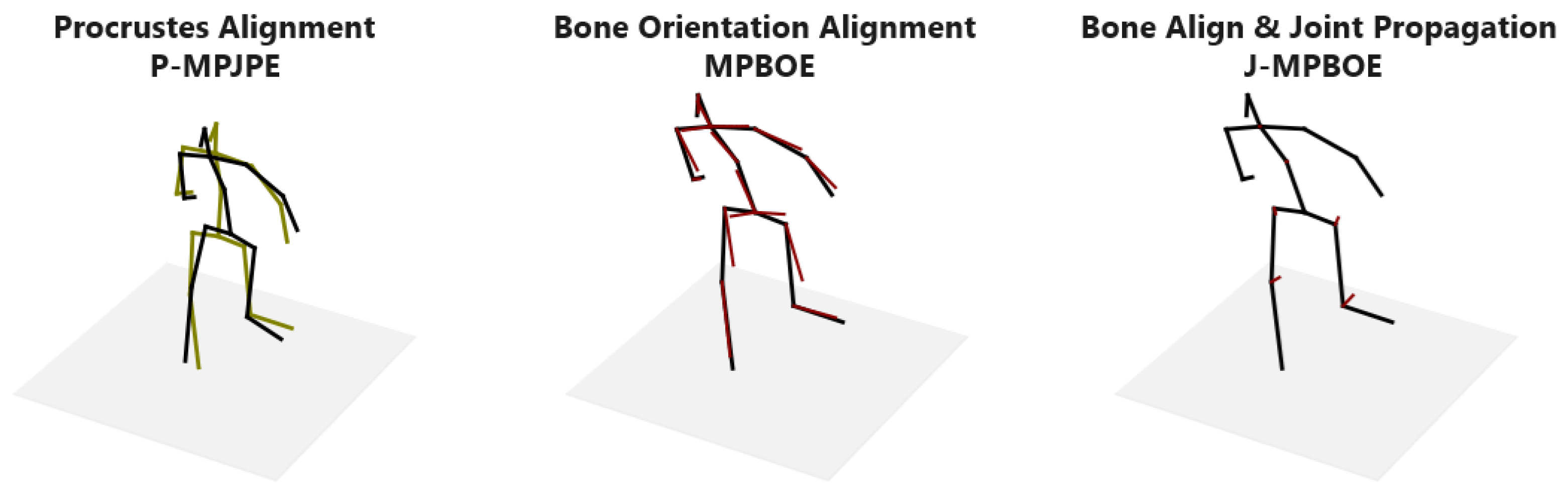
Following the Free-Bone alignment procedure, we can easily assess the dissimilarity between the isolated orientation of pairs of bones (i.e., the same bone in any two given 3D poses) by computing the distance between their aligned Free-Bone unit vectors. These can be pairs of bones in 3D poses estimated from different viewpoints or pairs of bones in an estimated 3D pose and the corresponding ground-truth 3D pose. This gives us a measure of the orientation of each pair of bones invariant to the global orientation, positioning, and scale of either 3D pose. Collectively, we can evaluate the posture similarity between pairs of 3D poses. Unlike the rigid alignment of the
Procrustes mean per-joint position error (P-MPJPE) that leads to numerical instabilities during backpropagation due to singular-value decomposition, our Free-Bone alignment procedure is fully differentiable as it involves basic addition, subtraction, multiplication, and division operations. This advantage over the P-MPJPE enables the direct optimization of 3D posture as a loss term when training a pose estimator. Our proposed
mean per-bone orientation error (MPBOE) for a batch of poses
P and set of bones
B is defined in Equation (
6).
where
d is a distance measure (e.g., L2-norm, L1-norm, or cosine similarity);
is the Free-Bone unit vector of the estimated 3D pose after alignment; and
is the corresponding Free-Bone unit vector of the ground-truth 3D pose after alignment. Both unit vectors are scaled by
, which is the length of the corresponding ground-truth bone. This normalization is critical to distribute the weight of the posture loss term amongst the bones of a 3D pose such that the influence of a bone’s orientation error is directly proportional to the length of the bone. Otherwise, shorter and more rigid torso bones would have the same influence as longer and more agile limb bones, resulting in poorer performance. This posture loss can be jointly optimized with the MPJPE as an auxiliary loss term in a fully supervised setting. It can also be minimized for weakly supervised multi-view poses in a semi-supervised setting as in Equation (
7).
Given a set of cameras C, , is the Free-Bone-aligned unit vector of the pose estimated for the viewpoint of camera c. Note that in a semi-supervised setting, there are no ground-truth 3D poses in the weakly supervised branch. is computed from the batch of annotated 3D poses in the fully supervised branch as the mean bone length of the corresponding bone. We set d as the L1-norm between vectors.
3.3.1. Semi-Supervision with Multi-View Posture Loss
Our semi-supervised training scheme, illustrated in
Figure 4, adopts the dual-branch (fully and weakly supervised) pipeline proposed by Pavllo et al. [
41] to train a 3D pose model and an auxiliary pose trajectory model.
We regularize the optimization of the weakly supervised 2D reprojection loss using the biomechanical pose prior regularizers proposed by Amadi and Agam [
6]. Each training batch is made up of 3 parts: (1) A set of 2D poses (with corresponding 3D pose annotations) for the fully supervised branch; (2) a set of 2D poses for the weakly supervised branch; and (3) a matching set of 2D poses from other camera viewpoints corresponding to the second set of 2D poses, also for the weakly supervised branch. Hence, for a batch of
k fully supervised 2D poses, we append
2D poses, where
m − 1 is the number of additional camera viewpoints selected per weakly supervised pose. This setup allows us to optimize multi-view pose and posture consistency during training but maintain monocular 3D pose estimation at inference. We minimize a generic multi-view pose consistency loss
in the weakly supervised branch when camera extrinsic parameters are obtainable. The trajectory model estimates the 3D position of the pose
with respect to the observing camera. Combined with the camera’s extrinsic parameters
, we transform the estimated pose
(in camera frame
c) to a 3D pose in world coordinates
.
The multi-view pose loss is computed in Equation (
8) as the mean Euclidean distance between joint pairs (
and
) of the corresponding multi-view poses transformed to world coordinates.
P is the first set of estimated 3D poses in the weakly supervised branch, and
J is the set of joints in a 3D pose.
denotes the transformation function. Given a pose
∈
P,
is a corresponding pose estimated from another viewpoint that is contained in the second set of multi-view poses in the weakly supervised branch.
We apply horizontal flip augmentation to the 2D pose inputs of the weakly supervised branch to generate more unlabeled training data. This simple pose augmentation technique has been effective in previous works. However, once 2D poses are flipped in the image frame, we expect the resulting 3D pose to be flipped in the camera frame. This will cause a mismatch in multi-view 3D poses as each pose is flipped in its camera frame and will not align when transformed to standard world coordinates. Hence, we cannot optimize the multi-view pose consistency loss for such poses even if the camera’s extrinsic properties are known, as this will lead to degenerated results. We can, however, optimize multi-view posture consistency loss for the reflected poses, as the posture remains consistent across viewpoints even after horizontal flip augmentation.
3.3.2. Semi-Supervision without Camera Parameters
Although most 3D pose datasets provide camera parameter annotations, we understand that camera parameters are not so easily obtainable for crowdsourced in-the-wild video data. Since the ultimate goal of semi-supervised pose estimation is to leverage these unlabeled in-the-wild training data, we propose a modified semi-supervised scheme that does not rely on intrinsic and extrinsic camera parameters.
The main objective function of the weakly supervised branch is the reprojected 2D loss, which projects the encoded 3D pose back to the 2D image space and computes the Euclidean distance between keypoints of the input 2D pose and the projected 2D pose. The camera’s intrinsic parameters are necessary to project 3D poses to 2D poses. Hence, the reprojected 2D loss cannot be optimized without the camera’s intrinsic properties. We bypass having to estimate the camera’s internal parameters by replacing the non-linear projection with an orthographic projection. Orthographic projection gives an acceptable approximation of non-linear perspective projection up to scale when images are captured at a short distance and from cameras with negligible skew and distortion effects. It is safe to assume that this is the case for most crowdsourced video data. We then replace the auxiliary trajectory model with an auxiliary scale model that estimates the 3D-to-2D pose scale factor. Note that, as in
Section 3.3.1, the 3D poses are always estimated with respect to the root joint. That is, the pelvis joint should be at the Cartesian origin. The orthographic reprojected 2D loss is computed in Equation (
9) given an input 2D pose
, estimated 3D pose
, and 3D–2D scale factor
.
is the 2D position of the root joint.
where
is the orthographic projected 2D pose that excludes the depth of the 3D pose
. In addition, we optimize our proposed multi-view posture consistency loss in Equation (
7). Note that multi-view pose consistency loss is not applicable in this scenario because we assume that the camera’s extrinsic parameters are not available. The results show that posture loss significantly boosts the performance of semi-supervised pose estimators trained without camera parameters.
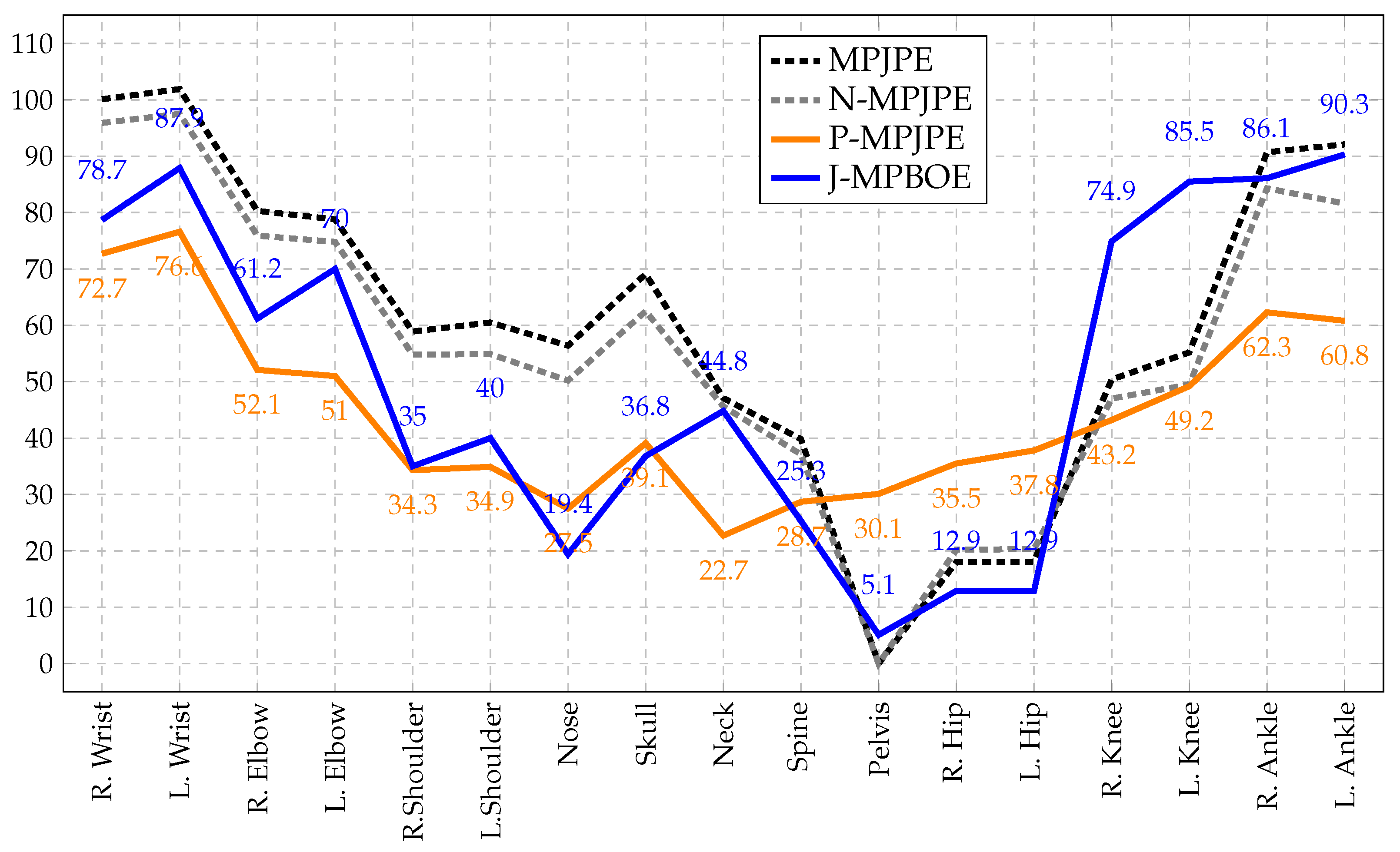
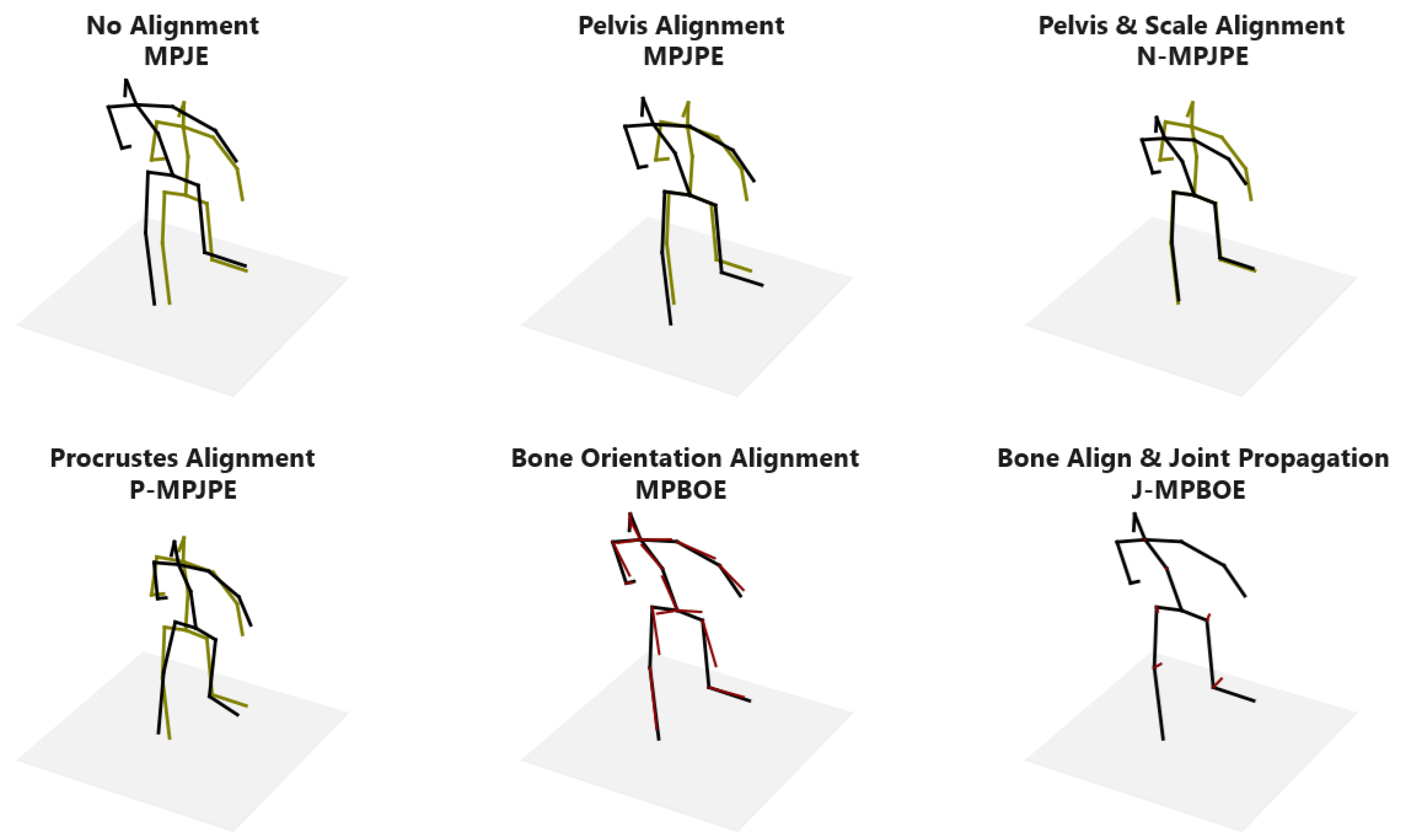
3.4. Bone Orientation Error as a Posture Metric
The proposed MPBOE is a notable posture evaluation metric because it captures and isolates errors to the exact bones that are incorrectly oriented. This property is quite unlike the P-MPJPE, a 3D pose protocol that technically measures posture alignment between poses. The rigid alignment procedure of the P-MPJPE computes an optimal rotation matrix, translation vector, and scale factor that best aligns a predicted pose to the ground-truth pose, thereby implicitly assessing posture. However, because an optimal rotation matrix is computed for the entire pose, an error in one joint is shared with other joints. In other words, the significant deviation of a joint is dampened, as it is distributed to other joints. This causes other more accurately predicted joints to further deviate from the ground truth. Therefore, we cannot pinpoint the most faulty joints when analyzing errors per joint. In contrast, because the bone orientation alignment procedure of the MPBOE aligns each bone separately, it can isolate errors to defaulting bones and corresponding quadruplet joints.
This distinguishing property is illustrated in
Figure 5 and demonstrated in detail in
Appendix A. To reconstruct the altered pose (in green), a sample 3D pose (in black) is shrunk and translated a distance to the left. We then slightly rotate the upper body at the pelvis joint. The outcome is that the original and altered pose now has a similar posture except for the lower-torso region. Observe that the best fit of the P-MPJPE shows an offset at almost all joints. Whereas, the MPBOE reveals the most significant deviations in the thigh and thorax bones that are in the lower-torso region, while other bones are in near-perfect alignment. In the results section, we show the joint errors of existing protocols compared to our proposed posture metric defined in Equation (
6). Note that the distance function
d can be the cosine similarity, L1-norm, or L2-norm. We compute the L2-norm.
Proof of Metric Property. The MPBOE qualifies as a metric because it satisfies the identity, positivity, symmetry, and triangle inequality properties of a metric space. This follows directly from the property of the distance measure d. Given two distinct postures and (Free-Bone vectors of 3D poses after bone orientation alignment), notice that and . Given a third posture that further deviates from , we expect . Proving the positivity property requires slightly more intuition. Given a posture , another posture can be generated that is very similar to except that we move the Anchor keypoint of a bone within the Anchor-Plane. Because the Anchor-Plane is unchanged, the orientation of the bone in both postures will align. Hence, , although the posture of the bones relative to their quadruplet keypoints is not the same. However, the deviation of that Anchor keypoint in will affect the orientation of a neighboring bone when it is used as the Pivot, Axis, or Free keypoint during alignment. Hence, . Therefore, . □
3.5. Bone Orientation Error Propagated to Joints
The bone orientation error (MPBOE) is bone-centric because it computes the orientation deviation between pairs of aligned bones. However, 3D pose estimation is joint-centric, as we are often interested in joint position errors. The orientation error of each bone can be propagated to the quadruplet joints used to align the bone, resulting in the
joint-propagated mean per-bone orientation error (J-MPBOE). We achieve this by attributing a weight
to each quadruplet joint
i of a bone. The error of a joint is accumulated by computing the weighted sum of the errors of all bones that use the joint (as one of the quadruplet keypoints) during alignment. To clarify, let
be the set of tuple pairs of bone errors
(with joint
j as a quadruplet keypoint) and corresponding quadruplet keypoint weight
. The accumulated error of the joint
is computed as in Equation (
10).
Provided the weight of all quadruplet keypoints for each bone sums to , the bone orientation error will be properly dispersed to affected joints without increasing or decreasing the cumulative posture error. We set the weights for the Free, Pivot, Axis, and Anchor keypoints to and for all bones, effectively assigning more importance to the Free and Pivot keypoints that define the bone. Therefore, the J-MPBOE captures and concentrates 3D pose reconstruction errors to the exact out-of-position joints that cause incorrect posture and bone orientations.


