
A Doherty Power Amplifier for Ultrasound Instrumentation
Department of Electronic Engineering, Gachon University, 1342 Seongnam-daero, Sujeong-gu, Seongnam 13120, Gyeonggi-do, Republic of Korea
Sensors 2023, 23(5), 2406; https://doi.org/10.3390/s23052406
Submission received: 15 December 2022
/
Revised: 29 January 2023
/
Accepted: 30 January 2023
/
Published: 21 February 2023
(This article belongs to the Special Issue Nondestructive Sensing and Imaging in Ultrasound)
Abstract
:The ultrasound instrumentation uses linear power amplifiers with low power efficiency, generating unwanted heat and resulting in the deterioration of the echo signal quality of measured targets. Therefore, this study aims to develop a power amplifier scheme to increase power efficiency while maintaining appropriate echo signal quality. In communication systems, the Doherty power amplifier has shown relatively good power efficiency while producing high signal distortion. The same design scheme cannot be directly applied to ultrasound instrumentation. Therefore, the Doherty power amplifier needs to be re-designed. To verify the feasibility of the instrumentation, a Doherty power amplifier was designed to obtain high power efficiency. The measured gain, output 1-dB compression point, and power-added efficiency of the designed Doherty power amplifier were 33.71 dB, 35.71 dBm, and 57.24% at 25 MHz, respectively. In addition, the performance of the developed amplifier was measured and tested using the ultrasound transducer through the pulse-echo responses. The output power with 25 MHz, 5-cycle, and 43.06 dBm generated from the Doherty power amplifier was sent through the expander to the focused ultrasound transducer with 25 MHz and 0.5″ diameter. The detected signal was sent via a limiter. Afterwards, the signal was amplified by a 36.8 dB gain preamplifier, and then displayed in the oscilloscope. The measured peak-to-peak amplitude in the pulse-echo response with an ultrasound transducer was 0.9698 V. The data showed a comparable echo signal amplitude. Therefore, the designed Doherty power amplifier can improve the power efficiency used for medical ultrasound instrumentation.
1. Introduction
Ultrasound instrumentation is non-invasive compared to X-ray-based computed tomography and positron emission tomography [1,2,3,4]. As the semiconductor technology node is smaller, the fabrication cost per transistor is lower, while several features are integrated into wireless applications [5,6]. With this improvement, the size of ultrasound instrumentations can be compact, so it could be used in the emergency rooms and ambulances [7]. Therefore, several ultrasound companies have developed different types of ultrasound instrumentations with array-type transducers [8,9,10].
The typical ultrasound instrumentations are composed of ultrasound transmitters, receivers, and transducers [11,12,13]. Among the components in ultrasound instrumentations, the power amplifiers in the ultrasound transmitters and analog-digital-converters in the ultrasound receivers are the most critical electronic component units for direct current (DC) power consumption, respectively [14]. Therefore, the performances of the power amplifiers could affect the whole power consumptions of the ultrasound transmitters. Compared to general ultrasound instrumentations utilizing the alternating current (AC) power cords, portable medical ultrasound machines have limited battery lives [15,16]. Proper design and performances of the power amplifiers are complicated that can affect the performances of ultrasound instrumentations. Therefore, the power amplifiers for such instrumentations could be properly designed to obtain the adequate power efficiency of the ultrasound machines while generating improved performances, such as sensitivities and harmonic distortions of the echo signals generated by ultrasonic transducers [17]. For portable medical ultrasound instrumentations, power efficiency could be a more serious issue compared to general bench-top ultrasound instrumentations, because driving higher power in the portable ultrasound instrumentations can yield an adequate sensitivity of the ultrasound transducers, which are related to the performances of ultrasound instrumentations [18,19]. Therefore, high voltage driving powers are required here. However, they might lead to lower battery lives [20,21,22].
The general power amplifiers are classified into linear and non-linear power amplifiers used in ultrasound instrumentations [23,24]. The linear power amplifiers are Class-A-, Class-B-, and Class-AB-type power amplifiers with low power efficiency and low signal distortions [25]. For general ultrasound instrumentations using AC power cords, linear power amplifiers have been used because they provide low harmonic signal distortions generated by ultrasonic transducers that compensate for power efficiency characteristics [26].
In this paper, linear (Class-B and Class-AB) and non-linear (Class-D, Class-DE, and Class-E) power amplifiers are shown for general ultrasound imaging and high-intensity focused ultrasound (HIFU) applications. A Class-B power amplifier was developed for an ultrasound instrumentation [27]. A 0.03 MHz Class-B power amplifier was designed to produce an output voltage of 396 V [28]. A 10 MHz Class-B power amplifier with an output power of 3.09 W, an output voltage of 27.25 V, and an efficiency of 5.66% was designed [29]. A Class-AB power amplifier with an output voltage of 90 V and a bandwidth of 6.5 MHz was implemented [30]. An 18.5 MHz bandwidth Class-AB power amplifier was implemented [31]. A 50 MHz Class-AB power amplifier was designed [32].
The non-linear power amplifiers are Class-D-, Class-DE-, and Class-E-type power amplifiers with high power efficiency and high signal distortions [33,34]. A high voltage 3.5 kHz Class-D amplifier was designed [35]. A 0.1 MHz Class-D amplifier was designed [36]. A Class-DE power amplifier with a logic gate driver was developed [37]. A 1.54 MHz Class-E power amplifier was developed [38]. A Class-E inverter was designed to produce an optimal frequency of 40.07 kHz [39]. However, non-linear power amplifiers produce relatively high signal distortions.
To date, there is no Doherty power amplifier scheme developed for ultrasound applications. William H. Doherty first developed the Doherty power amplifier for radio communication system [40,41]. The Doherty power amplifier, which is one of the non-linear power amplifiers, has been used for low voltage communication systems with high power efficiency, but also high signal distortion. Higher power efficiency indicates that the power amplifier could consume a relatively lesser power consumption [42]. Therefore, the Doherty power amplifier could be one of the candidates for ultrasound instrumentation. However, one of the challenging technical issues is that the developed Doherty power amplifier must be properly working in the high voltage operations for ultrasound applications while still obtaining echo signal distortion of the ultrasound transducers. The design of such a power amplifier operating in high voltage operations is difficult to implement because the power transistor model in the large signal operations is less accurate than that in low voltage signal operations [43,44], even though other previous studies reported that the power transistor model is not accurate in low voltage signal operations. Compared to communication system applications, ultrasound applications must have adequate signal quality for harmonic ultrasound imaging applications [45,46,47]. Therefore, developed Doherty power amplifiers must be re-designed for ultrasound instrumentations. In addition, the selected components in the Doherty power amplifiers must properly work under high voltage operations.
This paper is organized as follows: Section 2 describes the schematic design, circuit analysis, and printed circuit board (PCB) implementation of the Doherty power amplifier for ultrasound instrumentation applications. Section 3 shows the experimental results of the Doherty power amplifiers, such as power efficiency and gain. In addition, the measured results are shown with ultrasound transducers because the Doherty power amplifier is customized for ultrasound applications. Section 4 presents the conclusion of the study.
2. Materials and Methods
The Doherty power amplifiers operate according to the load modulation theory [43,48]. In other words, the main power amplifier works in lower input power ranges. The main and auxiliary power amplifiers work together in higher input power ranges to obtain relatively high efficiency in wide input power ranges. Figure 1 shows the equivalent circuit model of the Doherty power amplifier to explain the concept of the load modulation.
Using the Kirchhoff’s current law, the output voltage (Vo) at the load impedance (RL) of the Doherty power amplifier can be expressed as follows [49,50,51]:
where Imo′ is the output current of the main power amplifier passing through the impedance transformer and IAUX is the output current of the auxiliary power amplifier.
The gain (G) and output power (Po) of the Doherty power amplifier could be calculated as
The load impedance at the main and auxiliary amplifiers (Zmpa′ and ZAUX) are expressed as
The input impedance of the Doherty power amplifier can be calculated by the impedance transformer.
The operating gate voltage of the auxiliary power amplifier is lower than that of the main amplifier. Therefore, the main power amplifier is only working for low input power ranges such that the impedance of the main power amplifier (Zmpa) is changed into the 2R0 [23]. The auxiliary power amplifier properly works such that the impedances of Zmpa′ and Zmpa are closed to R0 as the input power increases and reaches to the maximum input powers [23].
Figure 2a shows the block diagram of the Doherty power amplifier. The Doherty power amplifier consists of the main and auxiliary power amplifiers with impedance transformers. Figure 2b shows the implemented main, auxiliary, and developed Doherty power amplifiers on the custom-made PCB. For the power amplifier to work properly under high voltage operations, selected discrete components are high voltage or high current tolerant. The choke inductors with a maximum current of 2A and the transistors with a maximum drain-source voltage of 65 V were selected. In addition, the square heat-sink was attached on top of the transistors to reduce the temperature effects. In the output port, the high power resistors with maximum voltage of 250 V were used. The electrolytic capacitors with maximum voltage of 50 V in the gate and drain side of the transistor were also used. The next paragraph shows the detail architecture and operating mechanisms of the designed Doherty power amplifier.
Figure 3 shows the schematic of the main power amplifier. The main transistor in power amplifiers is a lateral diffusion metal oxide semiconductor (LDMOS) transistor, which is suitable for high voltage operation because of considerably high breakdown voltage [52]. The transistor (T1) was used for main and auxiliary power amplifiers. The input and output DC coupling capacitors (C1 and C4) were used in the main power amplifier to block unwanted DC voltages [53]. The bias feed resistor (R2) was used to provide the bias voltage of the transistor (T1). The choke inductor (L2) was used to minimize the supply voltage reduction [54,55]. According to the transistor datasheet, the same values of the electrolytic capacitors and ceramic capacitors were used. The electrolytic capacitor (CG1 = 10 μF) and ceramic capacitors (CG2, CG3, and CG4 = 0.1 μF, 1000 pF, and 47 pF, respectively) in the gate side of the transistor (T1) and the electrolytic capacitor (CD1 = 220 μF) and ceramic capacitors (CD2, CD3, and CD4 = 220 μF, 0.1 μF, 100 pF, and 47 pF, respectively) in the drain side of the transistor (T1) were used. In the input port, low pass filters were composed of the resistor (R1), inductor (L1), and capacitor (C1). In the output port, low pass filters composed of the capacitors (C4, C5, and C6) and inductors (L3 and L4) were used.
The schematic of the auxiliary power amplifier is shown in Figure 4. The input and output DC coupling capacitors (C9 and C12) were used in the auxiliary power amplifier to block unwanted DC voltages [56]. The bias feed resistor (R4) was used to provide the bias voltages to the transistor (T2). The choke inductor (L6) was used to minimize the voltage reduction [57,58]. The electrolytic capacitor (CG1 = 10 μF) and ceramic capacitors (CG2, CG3, and CG4 = 0.1 μF, 1000 pF, and 47 pF, respectively) for the gate side in the transistor (T2) and the electrolytic capacitor (CD1 = 220 μF) and ceramic capacitors (CD2, CD3, and CD4 = 0.1 μF, 100 pF, and 47 pF, respectively) for the drain side in the transistor (T2) were used. In the input port, low pass filters were composed of the capacitors (C7 and C8) and inductor (L4). In the output port, low pass filters composed of the resistor (R5), capacitors (C13 and C14), and inductor (L7) were used.
For the Doherty power amplifier used in communication applications, the impedance transformer is implemented as transmission lines [59,60]. However, the working frequencies and voltages in ultrasound systems are less than a few hundred MHz and are higher than a few volts, which are high voltage ranges such that the impedance transformer was re-designed used for ultrasound applications. The developed impedance transformers were only used [33]. The input signals were spitted equally using the Wilkinson power divider circuit [41]. Subsequently, they were transmitted to the main and auxiliary amplifiers.
The impedance transformer was implemented to remove the harmonic components. The Wilkinson power divider was used to equally divide the input. The Wilkinson power divider was composed of three capacitors, two inductors, and one resistor (R6).
The simulated results of the Doherty power amplifier under high voltage operations were not provided. First, the simulation results of the signal distortions of the power amplifiers do not provide accurate results as mentioned in a previous study [34]. The simulation libraries of some discrete components, such as power resistors and choke inductors, which are composed of the Wilkinson power divider, as well as the impedance transformer, are not provided from the manufacturers. In addition, the designed Doherty power amplifier must work under high voltage operations such that the simulated results do not show the accurate results because the real performance of the power amplifier is affected by the temperature effect [61]. Therefore, some discrepancy values between expected and measured results of the Doherty power amplifier performance are expected.
3. Results and Discussion
3.1. Performance Measurements for Main, Auxiliary, and Doherty Power Amplifiers
One of the important specifications of the power amplifiers is the output power versus the input power with the output 1-dB compression point (OP1dB), gain, and power-added efficiency (PAE). The OP1dB is the index of the linearity of the power amplifier [62]. The linearity is related with the signal distortions of the amplifier [63]. The PAE is the index of the power consumption of the power amplifier and is defined as the ratio of the AC output power to the DC input power [64].
Two power supplies (E3631A and 2231A-3-30, Keysight Technology, Santa Rosa, CA, USA) provided DC to the power amplifiers. For obtaining the output power and PAE, the five-cycle pulses generated from function generator (AFG3252C, Tektronix Inc., Beaverton, OR, USA) were utilized for the ultrasound applications because multi-cycle pulses were applied to operate the ultrasound transducers [65]. These pulses were amplified using power amplifiers, and their amplified pulses were displayed on the oscilloscope through a power attenuator. Figure 5 shows the experimental setup to measure the output power and PAE.
Figure 6 shows the measured gain of the main, auxiliary, and Doherty power amplifiers. The gain of the Doherty power amplifier was improved with the help of the main and auxiliary power amplifiers. The input power was calculated by multiplying the measured voltage and current signals. The operating gate voltage of the auxiliary power amplifier is lower than that of the main power amplifier. Therefore, the gain of the auxiliary power amplifier (2.78 dB) was lower than that of the main power amplifier (29.51 dB) at input power of −12 dBm, as shown in Table 1. As described in Equation (4), the impedance of the auxiliary power amplifier is closed to R0 as the input current (IAUX) increases. Therefore, the auxiliary power amplifier properly works such that the gain of the Doherty power amplifier was saturated at a certain input power level. The gain of the main, auxiliary, and Doherty power amplifiers were measured as 29.42, 11.40, and 35.56 dB at 3.0 dBm, respectively, and the gain of the main, auxiliary, and Doherty power amplifiers were measured as 29.04, 20.95, and 33.71 dB at 12 dBm, respectively.
Table 1 shows the measured gain versus the input power performance of the main, auxiliary, and Doherty power amplifiers.
The Doherty power amplifier is one of the non-linear power amplifiers with good PAE at relatively high signal distortions [41]. However, ultrasound echo signal distortions could affect the image resolution [66]. Therefore, the designed Doherty power amplifier for ultrasound applications must have good PAE and adequate signal distortions. This indicates that the performance trade-off between the PAE and signal distortions could be compromised if we designed the Doherty power amplifier used for ultrasound transducers.
Figure 7 shows the measured output power versus input power with OP1dB of the main, auxiliary, and Doherty power amplifiers. The OP1dB of the main, auxiliary, and Doherty power amplifiers were measured as 31.04 dBm at 12.0 dBm, 11.70 dBm at 6.0 dBm, and 35.71 dBm at 12.0 dBm input powers, respectively, as shown in Figure 8. As mentioned before, the gate voltage of the auxiliary power amplifier is lower than that of the main power amplifier so the output power of the auxiliary power amplifier (−19.22 dBm) was lower than that of the main power amplifier (7.51 dBm) at an input power of −12 dBm as shown in Table 2. However, the impedances of the main and auxiliary power amplifiers were reached to R0 so that the output power of both power amplifiers would be increased accordingly. In the figure, the measured OP1dB (35.71 dBm) of the Doherty power amplifier was improved compared to those (11.70 dBm at 31.04 dBm) of the main and auxiliary power amplifier accordingly.
Table 2 lists the measured output power versus the input power performance of the main, auxiliary, and Doherty power amplifiers.
Figure 8 shows the measured PAE of the main, auxiliary, and Doherty power amplifiers. Because of the load modulation condition, the impedances of the main power amplifier and Doherty power amplifier (Zmpa′ and Zmpa) in the maximum power level are close to R0 [41]. Even though the input power increases, the impedances of the main and auxiliary power amplifiers were adjusted, so substantial output powers of the main and auxiliary power amplifiers were fed into the output power of the Doherty power amplifier [41]. Therefore, the PAE of the Doherty power amplifier would be increased and then reach the maximum PAE at the saturation point. In this figure, the measured PAE of the main, auxiliary, and Doherty power amplifiers were 40.99%, 48.25%, and 57.24% at an input power of 27.0 dBm, respectively. The measured PAE of the Doherty power amplifiers shows good PAE values for portable instrumentation.
Table 3 summarizes the measured PAE versus the input power of the main, auxiliary, and Doherty power amplifiers. These measurement results confirm that the Doherty power amplifier could be useful for ultrasound instrumentation.
3.2. Pulse-Echo Measurement with Ultrasound Transducer
The Doherty power amplifier can optimize power consumption such that good power efficiency could be achieved. However, the harmonic signal distortions of the echo signals are also important in obtaining high signal quality in ultrasound instrumentation [67,68,69]. Therefore, the performances of the power amplifiers were measured in the pulse-echo measurement setup, which is a common evaluation method of ultrasound devices [70].
Figure 9 illustrates the pulse-echo measurement when using the main, auxiliary power amplifiers, and Doherty power amplifiers. The DC voltages generated by two power supplies (E3531A and 2231A-3-30) and five-cycle pulse signals fed by the function generator (AFG3252C) were applied to the power amplifier. The high voltage pulse signals amplified by the power amplifier fed into a 25 MHz and 0.5″ diameter focused ultrasound transducer through an expander. The expander consists of a cross-coupled diode pair in the aluminum enclosure box. The echo signals detected by the ultrasound transducer pass through a limiter. Then, they were amplified by a preamplifier with a 36.8 dB voltage gain. The limiter is composed of a 50-ohm resistor shunt with a cross-coupled diode in the aluminum enclosure box. Finally, these echo signals obtained in the oscilloscope were recorded in the computer.
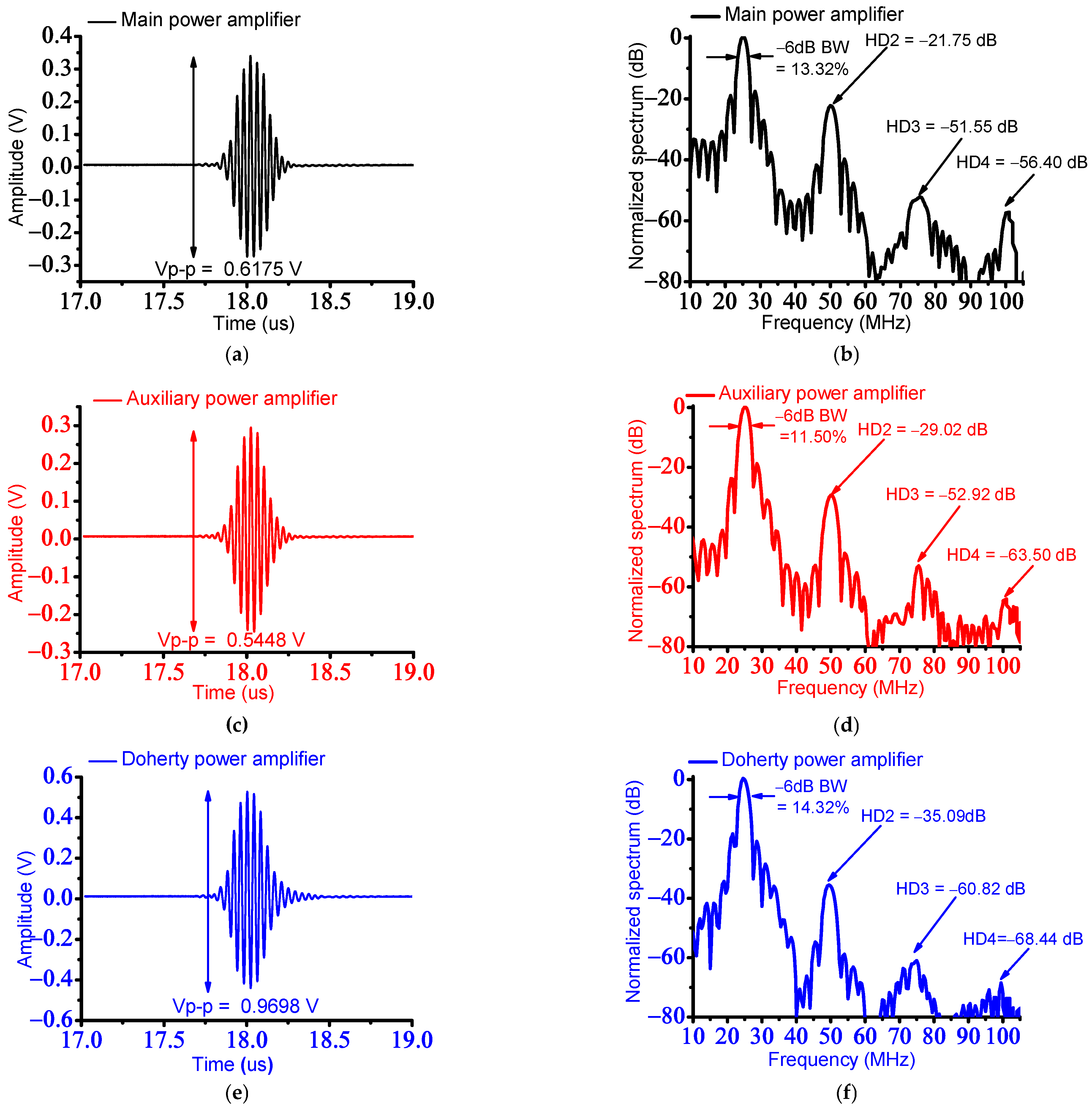
Figure 10 shows the data of the amplitudes and spectra when using a 25 MHz ultrasound transducer with a power amplifier. The outputs of the main and auxiliary power amplifiers would be properly increased, so the Doherty power amplifier would be effectively improved; therefore, the measured echo signal amplitudes of the main, auxiliary, and Doherty power amplifiers were shown. With the trial and error method, the high PAE and relatively adequate harmonic distortion performances of the designed Doherty power amplifier were obtained because those performance parameters of the Doherty power amplifier have a trade-off relationship.
As shown in Figure 10a,c,e, the measured amplitudes of the echo signals when using the main, auxiliary, and Doherty power amplifiers were 0.6175 Vp-p, 0.5448 Vp-p, and 0.9698 Vp-p, respectively, because the Doherty power amplifier has the highest gain among others. As shown in Figure 10b,d,f, the measured −6 dB bandwidths of the main, auxiliary, and Doherty power amplifiers were 13.32%, 11.50%, and 14.32%, respectively. The measured second, third, and fourth harmonic-distortion components (HD2 = −35.09 dB, HD3 = −60.82 dB, and HD4 = −68.44 dB) of the echo signals generated with the Doherty power amplifier were lower than those of the measured second, third, and fourth harmonic-distortion components (HD2 = −21.75 dB, HD3 = −51.55 dB, and HD4 = −56.40 dB) of the echo signals generated by the main power amplifier, respectively. The calculated total harmonic distortions (THDs) of the echo signals of the ultrasound transducer driven by the main, auxiliary, and Doherty power amplifiers were −43.48 dB, −58.00 dB, and −70.15 dB, respectively.
Table 4 summarizes measured performance of the peak-to-peak amplitude, −6 dB bandwidths, and HD2, HD3, HD4, and THD of the main, auxiliary, and Doherty power amplifiers. The measured performance of the Doherty power amplifier is improved, as shown in Table 4.
Table 5 summarizes the comparison of the currently developed power amplifiers for ultrasound transducer applications. The developed Doherty power amplifier has high PAE because the power amplifier performance decreased because of the non-linear characteristics of the transistor [71]. The efficiency of the power amplifier can be obtained by the output power divided by input DC power so the efficiency of the Doherty power amplifier was added in Table 5. A 325LA commercial amplifier has harmonic level less than −23 dBc. Each power amplifier scheme has different target parameters, such as output power, HD3, or efficiency, because there could be trade-off between each parameter. Therefore, each power amplifier has a higher performance parameter, scarifying other performance parameters.
4. Conclusions
The performances of the ultrasound instrumentations are restricted by the limited power consumption because of the limited battery life for severe environments in emergency rooms and ambulances. Due to limited power restriction, the structure size and numbers of array transducers, which are components in the ultrasound instrumentations, are smaller. Therefore, this can be the bottleneck of the echo signal performances and view angles of the target for ultrasound instrumentations.
The power amplifier used in the ultrasound instrumentations is one of the problems for consuming power and generating unwanted heat, thus reducing the performances of the instrumentation. A new type of Doherty power amplifier was developed to reduce DC power consumption of the power amplifier while producing adequate sensitivities of the ultrasound transducers. For communication areas, the Doherty power amplifier has been used for communication applications. However, this scheme has never been used for any ultrasound transducer applications and cannot be directly used because of different operation mechanisms and environments. Therefore, the new Doherty power amplifier scheme must be developed to be applied for ultrasonic transducers. The Doherty power amplifier was developed with the main and auxiliary power amplifier, impedance transformer, and Wilkinson power divider. The gain and OP1dB of the Doherty power amplifier were measured as 33.71 dB and 35.71 dBm at 12 dBm, respectively. The measured PAE of the Doherty power amplifier was 57.24% at 27.0 dBm.
To verify the feasibility, the pulse-echo responses were performed, and the performance of the power amplifier was measured using a 25 MHz ultrasound transducer. In the pulse-echo response with the ultrasound transducer, the measured peak-to-peak voltage amplitude of the echo signal when using the Doherty power amplifiers was 0.9698 Vp-p. The measured −6 dB bandwidth when using Doherty power amplifiers was 14.32%. The measured second, third, and fourth harmonic-distortion components of the signals generated with the Doherty power amplifier are HD2 = −35.09 dB, HD3 = −60.82 dB, and HD4 = −68.44 dB, respectively. The measured THD was −70.15 dB. These measurement data show adequate harmonic distortions of the echo signals of the ultrasound transducers while consuming the low DC power consumption of the power amplifier. Therefore, the newly developed Doherty power amplifier can potentially be used for maintaining the performances of medical ultrasound instrumentation by improving the power-added efficiency of the power amplifier.
Funding
This work was supported by the National Research Foundation of Korea (NRF) grant funded by the Korea government (MSIT) (No. 2020R1A2C4001606).
Institutional Review Board Statement
Not applicable for studies not involving humans or animals.
Informed Consent Statement
Not applicable for studies not involving humans.
Data Availability Statement
The data presented in this study are included within the article.
Conflicts of Interest
The authors declare no conflict of interest. The funders had no role in the design of the study; in the collection, analyses, or interpretation of data; in the writing of the manuscript; or in the decision to publish the results.
References
- He, Z.; Zheng, F.; Ma, Y.; Kim, H.H.; Zhou, Q.; Shung, K.K. A sidelobe suppressing near-field beamforming approach for ultrasound array imaging. J. Acoust. Soc. Am. 2015, 137, 2785–2790. [Google Scholar] [CrossRef] [PubMed] [Green Version]
- Yan, F.; Li, X.; Jin, Q.; Jiang, C.; Zhang, Z.; Ling, T.; Qiu, B.; Zheng, H. Therapeutic Ultrasonic Microbubbles Carrying Paclitaxel and LyP-1 Peptide: Preparation, Characterization and Application to Ultrasound-Assisted Chemotherapy in Breast Cancer Cells. Ultrasound Med. Biol. 2011, 37, 768–779. [Google Scholar] [CrossRef] [PubMed]
- Kim, J.; You, K.; Choi, H. Post-Voltage-Boost Circuit-Supported Single-Ended Class-B Amplifier for Piezoelectric Transducer Applications. Sensors 2020, 20, 5412. [Google Scholar] [CrossRef]
- Kim, J.; You, K.; Choe, S.-H.; Choi, H. Wireless Ultrasound Surgical System with Enhanced Power and Amplitude Performances. Sensors 2020, 20, 4165. [Google Scholar] [CrossRef]
- Lee, T.H. The Design of CMOS Radio-Frequency Integrated Circuits; Cambridge University Press: Cambridge, UK, 2006. [Google Scholar]
- Razavi, B. RF Microelectronics; Prentice Hall: Upper Saddel River, NJ, USA, 2011. [Google Scholar]
- Kim, G.-D.; Yoon, C.; Kye, S.-B.; Lee, Y.; Kang, J.; Yoo, Y.; Song, T.-K. A single FPGA-based portable ultrasound imaging system for point-of-care applications. IEEE Trans. Ultrason. Ferroelectr. Freq. Control 2012, 59, 1386–1394. [Google Scholar]
- Davidsen, R.E.; Freeman, S.R.; Savord, B.J. Matrix Ultrasound Probe with Passive Heat Dissipation. U.S. Patent 9730677B2, 15 August 2017. [Google Scholar]
- Smith, J.A.; Jensen, O.C. Portable Ultrasound Scanner and Docking System. U.S. Patent 9,649,089, 16 May 2017. [Google Scholar]
- Little, B.; Duffy, T.; Coughlin, J. Systems for Ultrasound Beam Forming Data Control. U.S. Patent 9,671,491, 6 June 2017. [Google Scholar]
- Szabo, T.L. Diagnostic Ultrasound Imaging: Inside Out; Elsevier Academic Press: London, UK, 2013. [Google Scholar]
- Xu, M.; Yang, X.; Ding, M.; Yuchi, M. Spatio-temporally smoothed coherence factor for ultrasound imaging. IEEE Trans. Ultrason. Ferroelectr. Freq. Control 2014, 61, 182–190. [Google Scholar] [CrossRef] [PubMed]
- You, K.; Choi, H. Wide Bandwidth Class-S Power Amplifiers for Ultrasonic Devices. Sensors 2020, 20, 290. [Google Scholar] [CrossRef] [PubMed] [Green Version]
- Mason, T.J.; Peters, D. Practical Sonochemistry: Power Ultrasound Uses and Applications; Woodhead Publishing: Cambridge, UK, 2002. [Google Scholar]
- Choi, H. Stacked Transistor Bias Circuit of Class-B Amplifier for Portable Ultrasound Systems. Sensors 2019, 19, 5252. [Google Scholar] [CrossRef] [PubMed] [Green Version]
- Moore, C.L.; Copel, J.A. Point-of-care Ultrasonography. N. Engl. J. Med. 2011, 364, 749–757. [Google Scholar] [CrossRef] [PubMed] [Green Version]
- Choi, H. Class-C Linearized Amplifier for Portable Ultrasound Instruments. Sensors 2019, 19, 898. [Google Scholar] [CrossRef] [PubMed] [Green Version]
- Soni, N.J.; Arntfield, R.; Kory, P. Point of Care Ultrasound; Elsevier Health Sciences: Oxford, UK, 2014. [Google Scholar]
- Daniels, J.M.; Hoppmann, R.A. Practical Point-of-Care Medical Ultrasound; Springer: New York, NY, USA, 2016. [Google Scholar]
- McCafferty, J.; Forsyth, J.M. Point of Care Ultrasound Made Easy; CRC Press: Boca Raton, FL, USA, 2020. [Google Scholar]
- Adhikari, S.; Blaivas, M. The Ultimate Guide to Point-of-Care Ultrasound-Guided Procedures; Springer: Berlin, Germany, 2019. [Google Scholar]
- You, K.; Kim, S.-H.; Choi, H. A Class-J Power Amplifier Implementation for Ultrasound Device Applications. Sensors 2020, 20, 2273. [Google Scholar] [CrossRef]
- Albulet, M. RF Power Amplifiers; SciTech Publishing: London, UK, 2001. [Google Scholar]
- Vuolevi, J.; Rahkonen, T. Distortion in RF Power Amplifiers; Artech house: London, UK, 2003. [Google Scholar]
- Choi, H.; Choe, S.-W. Therapeutic Effect Enhancement by Dual-bias High-voltage Circuit of Transmit Amplifier for Immersion Ultrasound Transducer Applications. Sensors 2018, 18, 4210. [Google Scholar] [CrossRef] [PubMed] [Green Version]
- Choe, S.-W.; Choi, H. Suppression Technique of HeLa Cell Proliferation Using Ultrasonic Power Amplifiers Integrated with a Series-Diode Linearizer. Sensors 2018, 18, 4248. [Google Scholar] [CrossRef] [PubMed] [Green Version]
- Weibao, Q.; Yanyan, Y.; Fu Keung, T.; Lei, S. A multifunctional, reconfigurable pulse generator for high-frequency ultrasound imaging. IEEE Trans. Ultrason. Ferroelectr. Freq. Control 2012, 59, 1558–1567. [Google Scholar] [CrossRef] [PubMed]
- Kim, I.; Kim, J.; Choi, S.; Moon, W. Design of High Efficiency Power Amplifier for Parametric Array Transducer Using Variable Power Supply. In Proceedings of the 2014 International Power Electronics and Application Conference and Exposition, Shanghai, China, 5–8 November 2014; pp. 903–908. [Google Scholar]
- Capineri, L. A 15 MHz bandwidth, 60 Vpp, low distortion power amplifier for driving high power piezoelectric transducers. Rev. Sci. Instrum. 2014, 85, 104701. [Google Scholar] [CrossRef]
- Bianchi, D.; Quaglia, F.; Mazzanti, A.; Svelto, F. Analysis and Design of a High Voltage Integrated Class-B Amplifier for Ultra-Sound Transducers. IEEE Trans. Circuits Syst. I Regul. Pap. 2014, 61, 1942–1951. [Google Scholar] [CrossRef]
- Ku, P.-C.; Shih, K.-Y.; Lu, L.-H. A high-voltage DAC-based transmitter for coded signals in high frequency ultrasound imaging applications. IEEE Trans. Circuits Syst. I Regul. Pap. 2018, 65, 2797–2809. [Google Scholar] [CrossRef]
- Jian-Xing, W.; Yi-Chun, D.; Chia-Hung, L.; Pei-Jarn, C.; Tainsong, C. A Novel Bipolar Pulse Generator for High-Frequency Ultrasound System. In Proceedings of the 2013 IEEE International Ultrasonics Symposium (IUS), Prague, Czech Republic, 21–25 July 2013; pp. 1571–1574. [Google Scholar]
- Razavi, B. Design of Analog CMOS Integrated Circuits; McGraw-Hill Science: New York, NY, USA, 2016. [Google Scholar]
- Cripps, S.C. Advanced Techniques in RF Power Amplifier Design; Artech House: Norwood, MA, USA, 2002. [Google Scholar]
- Nielsen, D.; Knott, A.; Andersen, M.A.E. A High-Voltage Class D Audio Amplifier for Dielectric Elastomer Transducers. In Proceedings of the 2014 IEEE Applied Power Electronics Conference and Exposition—APEC 2014, Fort Worth, TX, USA, 16–20 March 2014; pp. 3278–3283. [Google Scholar]
- Agbossou, K.; Dion, J.-L.; Carignan, S.; Abdelkrim, M.; Cheriti, A. Class D Amplifier for a Power Piezoelectric Load. IEEE Trans. Ultrason. Ferroelectr. Freq. Control 2000, 47, 1036–1041. [Google Scholar] [CrossRef]
- Christoffersen, C.; Wong, W.; Pichardo, S.; Togtema, G.; Curiel, L. Class-DE ultrasound transducer driver for HIFU therapy. IEEE Trans. Biomed. Circuits Syst. 2016, 10, 375–382. [Google Scholar] [CrossRef]
- Lewis, G.K.L., Jr.; Olbricht, W.L. Design and characterization of a high-power ultrasound driver with ultralow-output impedance. Rev. Sci. Instrum. 2009, 80, 114704. [Google Scholar] [CrossRef] [PubMed]
- Yuan, T.; Dong, X.; Shekhani, H.; Li, C.; Maida, Y.; Tou, T.; Uchino, K. Driving an inductive piezoelectric transducer with class E inverter. Sens. Actuators A 2017, 261, 219–227. [Google Scholar] [CrossRef]
- Doherty, W.H. A new high efficiency power amplifier for modulated waves. Proc. IRE 1936, 24, 1163–1182. [Google Scholar] [CrossRef]
- Grebennikov, A.; Sokal, N.O.; Franco, M.J. Switchmode RF Power Amplifiers; Newnes: Amsterdam, The Netherlands, 2011. [Google Scholar]
- Kang, J.; Yu, D.; Min, K.; Kim, B. A ultra-high PAE Doherty amplifier basedon 0.13um CMOS process. IEEE Microw. Wirel. Compon. Lett. 2006, 16, 505–507. [Google Scholar] [CrossRef]
- Kazimierczuk, M.K. RF Power Amplifier; John Wiley & Sons: Hoboken, NJ, USA, 2014. [Google Scholar]
- Choi, H. Development of a Class-C Power Amplifier with Diode Expander Architecture for Point-of-Care Ultrasound Systems. Micromachines 2019, 10, 697. [Google Scholar] [CrossRef] [Green Version]
- Choi, H. Development of negative-group-delay circuit for high-frequency ultrasonic transducer applications. Sens. Actuators A 2019, 299, 111616. [Google Scholar] [CrossRef]
- Pornpromlikit, S.; Jeong, J.; Presti, C.D.; Scuderi, A.; Asbeck, P.M. A watt-level stacked-FET linear power amplifier in silicon-on-insulator CMOS. IEEE Trans. Microw. Theory Tech. 2010, 58, 57–64. [Google Scholar] [CrossRef]
- Choi, H.; Ryu, J.-M.; Choe, S.-W. A novel therapeutic instrument using an ultrasound-light-emitting diode with an adjustable telephoto lens for suppression of tumor cell proliferation. Measurement 2019, 147, 106865. [Google Scholar] [CrossRef]
- Colantonio, P.; Giannini, F.; Limiti, E. High Efficiency RF and Microwave Solid State Power Amplifiers; Wiley Online Library: Hoboken, NJ, USA, 2009. [Google Scholar]
- Golio, M.; Golio, J. RF and Microwave Circuits, Measurements, and Modeling; CRC Press: Boca Raton, FL, USA, 2018. [Google Scholar]
- Sedra, A.S.; Smith, K.C.; Carusone, T.C.; Gaudet, V. Microelectronic Circuits; Oxford University Press: New York, NY, USA, 2016. [Google Scholar]
- Allen, P.E.; Holberg, D.R. CMOS Analog Circuit Design; Oxford University Press: Oxford, UK, 2002. [Google Scholar]
- Huijsing, J.; Steyaert, M.; Van Roermund, A.H. Analog Circuit Design: Sensor and Actuator Interface Electronics, Integrated High-Voltage Electronics and Power Management, Low-Power and High-Resolution ADC’s; Springer Science & Business Media: Berlin, Germany, 2013. [Google Scholar]
- Choi, H.; Park, C.; Kim, J.; Jung, H. Bias-Voltage Stabilizer for HVHF Amplifiers in VHF Pulse-Echo Measurement Systems. Sensors 2017, 17, 2425. [Google Scholar] [CrossRef] [Green Version]
- Choi, H.; Woo, P.C.; Yeom, J.-Y.; Yoon, C. Power MOSFET Linearizer of a High-Voltage Power Amplifier for High-Frequency Pulse-Echo Instrumentation. Sensors 2017, 17, 764. [Google Scholar] [CrossRef]
- Davidse, J. Analog Electronic Circuit Design; Prentice Hall: Upper Saddle River, NJ, USA, 1991. [Google Scholar]
- Choi, H.; Yoon, C.; Yeom, J.-Y. A Wideband High-Voltage Power Amplifier Post-Linearizer for Medical Ultrasound Transducers. Appl. Sci. 2017, 7, 354. [Google Scholar] [CrossRef] [Green Version]
- Kim, K.; Choi, H. Novel Bandwidth Expander Supported Power Amplifier for Wideband Ultrasound Transducer Devices. Sensors 2021, 21, 2356. [Google Scholar] [CrossRef] [PubMed]
- You, K.; Choi, H. Inter-Stage Output Voltage Amplitude Improvement Circuit Integrated with Class-B Transmit Voltage Amplifier for Mobile Ultrasound Machines. Sensors 2020, 20, 6244. [Google Scholar] [CrossRef]
- Kingsley, N.; Guerci, J.R. Radar RF Circuit Design; Artech House: Norwood, MA, USA, 2016. [Google Scholar]
- Grebennikov, A. RF and Microwave Power Amplifier Design; McGraw-Hill: New York, NY, USA, 2005. [Google Scholar]
- Choi, H. Novel dual-resistor-diode limiter circuit structures for high-voltage reliable ultrasound receiver systems. Technol. Health Care 2022, 30, 513–520. [Google Scholar] [CrossRef] [PubMed]
- Baker, R.J. CMOS: Circuit Design, Layout, and Simulation; John Wiley & Sons: Hoboken, NJ, USA, 2008. [Google Scholar]
- Choi, H.; Li, X.; Lau, S.-T.; Hu, C.; Zhou, Q.; Shung, K.K. Development of Integrated Preamplifier for High-Frequency Ultrasonic Transducers and Low-Power Handheld Receiver. IEEE Trans. Ultrason. Ferroelectr. Freq. Control 2011, 58, 2646–2658. [Google Scholar] [CrossRef] [Green Version]
- Kim, K.; Choi, H. High-efficiency high-voltage class F amplifier for high-frequency wireless ultrasound systems. PLoS ONE 2021, 16, e02490342021. [Google Scholar] [CrossRef] [PubMed]
- Kim, K.; Choi, H. A New Approach to Power Efficiency Improvement of Ultrasonic Transmitters via a Dynamic Bias Technique. Sensors 2021, 21, 2795. [Google Scholar] [CrossRef]
- Choi, H.; Yeom, J.-Y.; Ryu, J.-M. Development of a Multiwavelength Visible-Range-Supported Opto–Ultrasound Instrument Using a Light-Emitting Diode and Ultrasound Transducer. Sensors 2018, 18, 3324. [Google Scholar] [CrossRef] [PubMed] [Green Version]
- Choi, H. Pre-Matching Circuit for High-Frequency Ultrasound Transducers. Sensors 2022, 22, 8861. [Google Scholar] [CrossRef] [PubMed]
- Jung, U.; Choi, J.H.; Choo, H.T.; Kim, G.U.; Ryu, J.; Choi, H. Fully Customized Photoacoustic System Using Doubly Q-Switched Nd: YAG Laser and Multiple Axes Stages for Laboratory Applications. Sensors 2022, 22, 2621. [Google Scholar] [CrossRef]
- Jung, U.; Choi, H. Active echo signals and image optimization techniques via software filter correction of ultrasound system. Appl. Acoust. 2022, 188, 108519. [Google Scholar] [CrossRef]
- Jeong, J.J.; Choi, H. An impedance measurement system for piezoelectric array element transducers. Measurement 2017, 97, 138–144. [Google Scholar] [CrossRef]
- Choi, H.; Jung, H.; Shung, K.K. Power Amplifier Linearizer for High Frequency Medical Ultrasound Applications. J. Med. Biol. Eng. 2015, 35, 226–235. [Google Scholar] [CrossRef] [PubMed] [Green Version]
Figure 1.
Equivalent circuit model of the Doherty power amplifier.

Figure 2.
(a) Configuration and (b) implemented PCB of the developed Doherty power amplifier.

Figure 3.
Schematic of the main power amplifier.
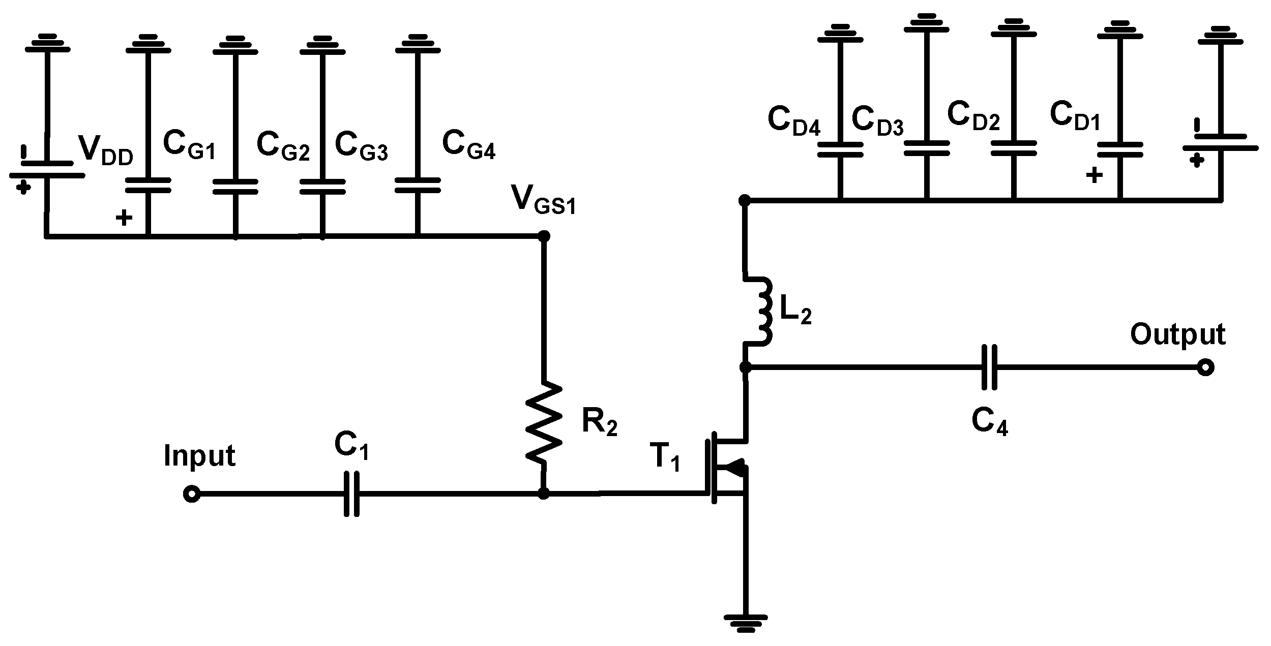
Figure 4.
Schematic of the auxiliary power amplifier.

Figure 5.
Measurement setup for output power, gain, P1dB, and PAE of the main, auxiliary, and Doherty power amplifiers.
Figure 5.
Measurement setup for output power, gain, P1dB, and PAE of the main, auxiliary, and Doherty power amplifiers.
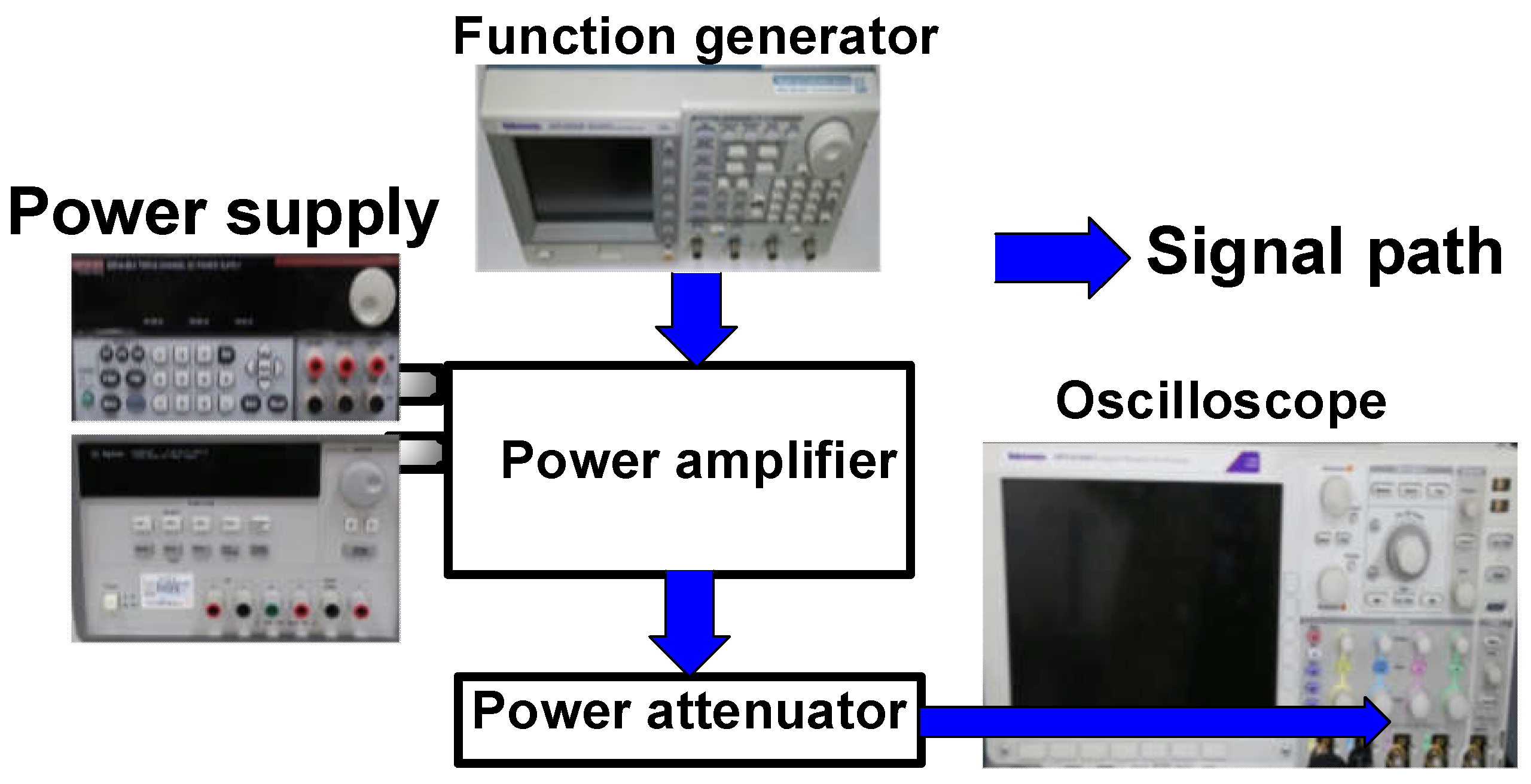
Figure 6.
Measured gain versus input power of the main, auxiliary, and Doherty power amplifiers.

Figure 7.
Measured output power versus input power with OP1dB of the main, auxiliary, and Doherty power amplifiers.
Figure 7.
Measured output power versus input power with OP1dB of the main, auxiliary, and Doherty power amplifiers.
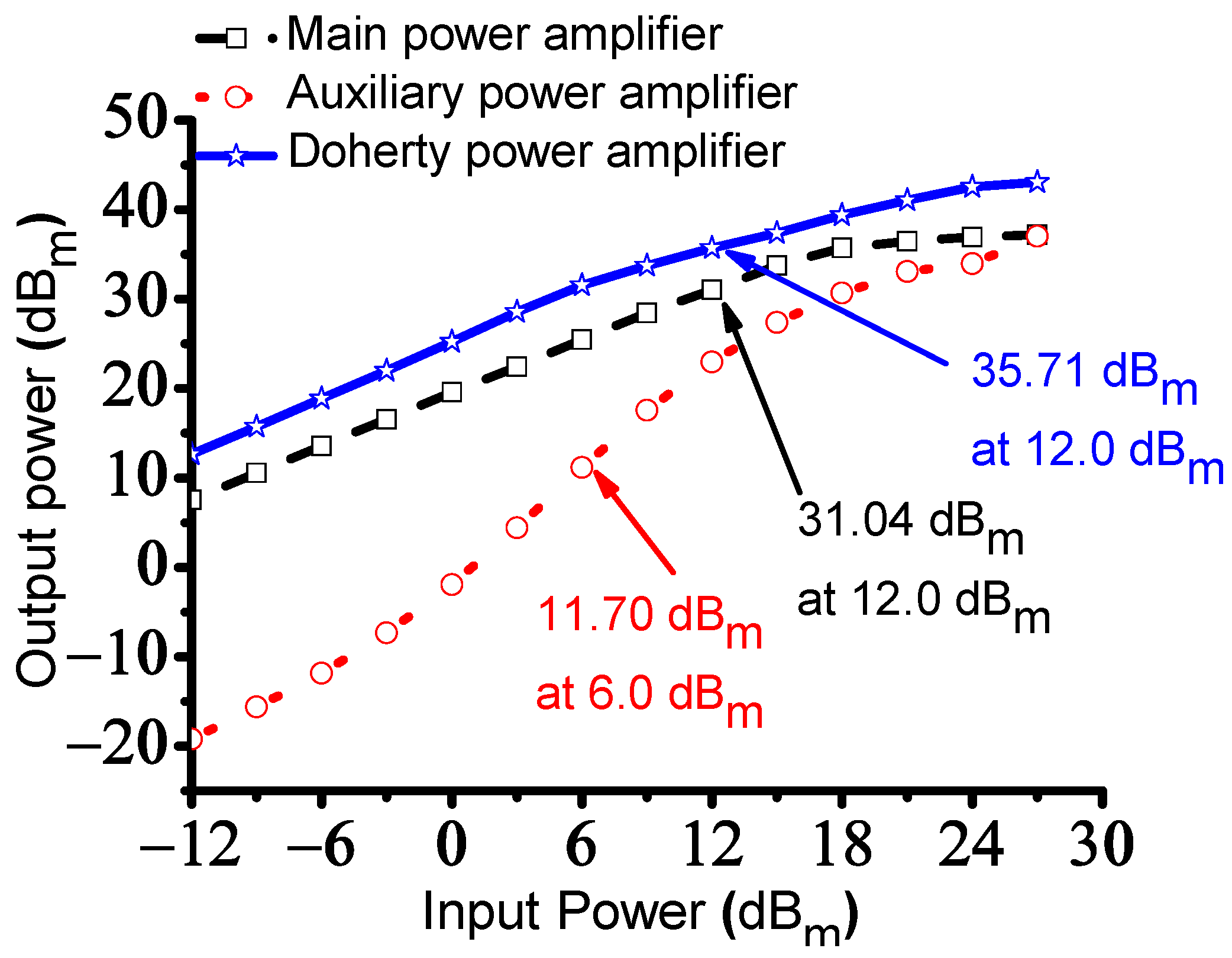
Figure 8.
Measured PAE versus input power of the main, auxiliary, and Doherty power amplifiers.
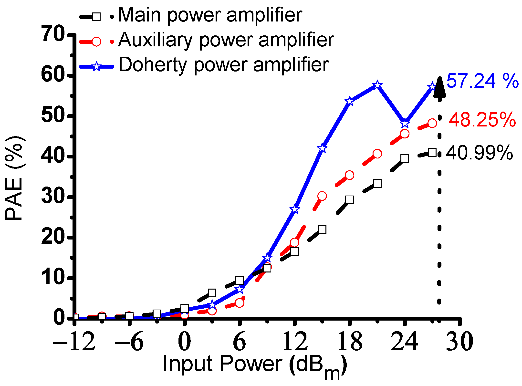
Figure 9.
Pulse-echo measurement setup using power amplifiers with an ultrasound transducer.
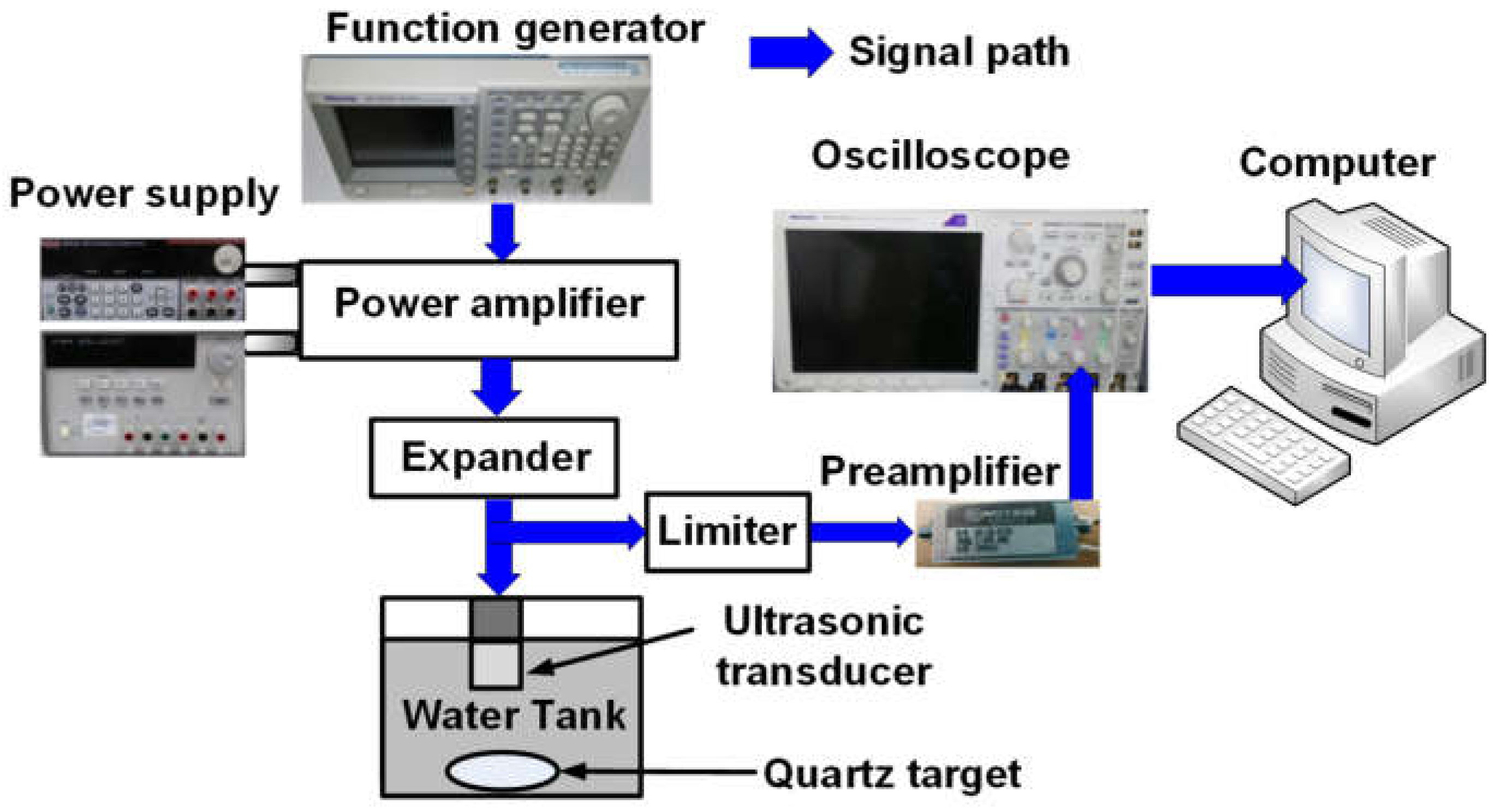
Figure 10.
Amplitudes of echo signals and normalized spectrum from a 25 MHz ultrasound transducer. (a) The amplitudes and (b) spectrum of the echo signal when using the main power amplifier. (c) The amplitudes and (d) spectrum of the echo signal when using the auxiliary power amplifier. (e) The amplitudes and (f) spectrum of the echo signal when using Doherty power amplifier.

Table 1.
Measured gain versus input power of the main, auxiliary and Doherty power amplifiers.
| Input Power (dBm) | Gain (dB) | ||
|---|---|---|---|
| Main Power Amplifier | Auxiliary Power Amplifier | Doherty Power Amplifier | |
| −12 | 29.51 | 2.78 | 31.66 |
| −9 | 29.56 | 3.36 | 32.52 |
| −6 | 29.57 | 4.14 | 33.69 |
| −3 | 29.56 | 5.67 | 34.45 |
| 0 | 29.60 | 8.05 | 34.78 |
| +3 | 29.42 | 11.40 | 35.56 |
| +6 | 29.45 | 15.17 | 35.56 |
| +9 | 29.44 | 18.56 | 34.72 |
| +12 | 29.04 | 20.95 | 33.71 |
| +15 | 28.74 | 22.40 | 32.36 |
| +18 | 27.71 | 22.69 | 31.39 |
| +21 | 25.44 | 22.08 | 30.04 |
| +24 | 22.92 | 19.95 | 28.57 |
| +27 | 20.21 | 20.04 | 26.06 |
Table 2.
Measured output power versus input power of the main, auxiliary, and Doherty power amplifiers.
Table 2.
Measured output power versus input power of the main, auxiliary, and Doherty power amplifiers.
| Input Power (dBm) | Output Power (dBm) | ||
|---|---|---|---|
| Main Power Amplifier | Auxiliary Power Amplifier | Doherty Power Amplifier | |
| −12 | 7.51 | −19.22 | 12.66 |
| −9 | 10.56 | −15.64 | 15.72 |
| −6 | 13.57 | −11.86 | 18.89 |
| −3 | 16.56 | −7.33 | 21.99 |
| 0 | 19.60 | −1.950 | 25.22 |
| +3 | 22.42 | 4.400 | 28.56 |
| +6 | 25.45 | 11.70 | 31.56 |
| +9 | 28.44 | 17.56 | 33.72 |
| +12 | 31.04 | 22.95 | 35.71 |
| +15 | 33.74 | 27.40 | 37.36 |
| +18 | 35.71 | 30.69 | 39.39 |
| +21 | 36.44 | 33.08 | 41.04 |
| +24 | 36.92 | 33.95 | 42.57 |
| +27 | 37.21 | 37.04 | 43.06 |
Table 3.
Measured PAE versus input power of the main, auxiliary, and Doherty power amplifiers.
| Input Power (dBm) | Main Power Amplifier | PAE (%) | |
|---|---|---|---|
| Auxiliary Power Amplifier | Doherty Power Amplifier | ||
| −12 | 0.26 | 0.17 | 0.0011 |
| −9 | 0.52 | 0.32 | 0.0015 |
| −6 | 0.61 | 0.61 | 0.01 |
| −3 | 0.81 | 1.18 | 0.54 |
| 0 | 1.01 | 2.49 | 2.15 |
| +3 | 2.02 | 6.33 | 3.41 |
| +6 | 3.89 | 9.38 | 7.24 |
| +9 | 12.72 | 12.46 | 15.00 |
| +12 | 18.79 | 16.55 | 26.97 |
| +15 | 30.26 | 21.98 | 42.04 |
| +18 | 35.45 | 29.32 | 53.62 |
| +21 | 40.72 | 33.33 | 57.64 |
| +24 | 45.66 | 39.48 | 48.16 |
| +27 | 48.25 | 40.99 | 57.24 |
Table 4.
Summary of the measured performance of the main, auxiliary, and Doherty power amplifiers with an ultrasound transducer.
Table 4.
Summary of the measured performance of the main, auxiliary, and Doherty power amplifiers with an ultrasound transducer.
| Amplitude (Vp-p) | −6 dB BW (%) | HD2 (dB) | HD3 (dB) | HD4 (dB) | THD (dB) | |
|---|---|---|---|---|---|---|
| Main Power Amplifier | 0.6175 | 13.32 | −21.75 | −51.55 | −56.40 | −43.48 |
| Auxiliary Power Amplifier | 0.5448 | 11.50 | −29.02 | −52.92 | −63.50 | −58.00 |
| Doherty Power Amplifier | 0.9668 | 14.32 | −35.09 | −60.82 | −68.44 | −70.15 |
Table 5.
Summary of the linear and non-linear power amplifiers for ultrasound applications.
| Circuit Architecture | Output Power (dBm) | Output Power (W) | Output Voltage (V) | Center Frequency or −3 dB BW (MHz) | Gain (dB) | HD2 (dB) | HD3 (dB) | HD4 (dB) | THD (dB) | PAE (%) | Efficiency (%) | Applications | |
|---|---|---|---|---|---|---|---|---|---|---|---|---|---|
| [28] | Class-B | 1120 | 396 | 0.03 | Parametric Transducer | ||||||||
| [29] | Class-B | 3.09 | 27.25 | 10 | 5.66 | Piezoelectric Actuator | |||||||
| [30] | Class-B | 90 | 6.5 | Piezoelectric Transducer | |||||||||
| [31] | Class-AB | 31.5 | 18.5 | Ultrasound Imaging | |||||||||
| [32] | Class-AB | 200 | 50 | Ultrasound Imaging | |||||||||
| [35] | Class-D | 125 | 0.035 | 43.5 | Dielectric Transducer | ||||||||
| [36] | Class-D | 0.1 | 95 | Piezoelectric Load | |||||||||
| [37] | Class-DE | 0.8 | 20 | 1.1 | −16.4 | HIFU Therapy | |||||||
| [38] | Class-E | 100 | 1.54 | High Power Driver | |||||||||
| [39] | Class-E | 0.219 | 0.04 | Piezoelectric Transducer | |||||||||
| This Work | Doherty | 35.71 | 25 | 33.71 | −35.09 | −60.82 | −68.44 | −70.15 | 57.24 | Piezoelectric Transducer |
Disclaimer/Publisher’s Note: The statements, opinions and data contained in all publications are solely those of the individual author(s) and contributor(s) and not of MDPI and/or the editor(s). MDPI and/or the editor(s) disclaim responsibility for any injury to people or property resulting from any ideas, methods, instructions or products referred to in the content. |
© 2023 by the author. Licensee MDPI, Basel, Switzerland. This article is an open access article distributed under the terms and conditions of the Creative Commons Attribution (CC BY) license (https://creativecommons.org/licenses/by/4.0/).
Share and Cite
MDPI and ACS Style
Choi, H. A Doherty Power Amplifier for Ultrasound Instrumentation. Sensors 2023, 23, 2406. https://doi.org/10.3390/s23052406
AMA Style
Choi H. A Doherty Power Amplifier for Ultrasound Instrumentation. Sensors. 2023; 23(5):2406. https://doi.org/10.3390/s23052406
Chicago/Turabian StyleChoi, Hojong. 2023. "A Doherty Power Amplifier for Ultrasound Instrumentation" Sensors 23, no. 5: 2406. https://doi.org/10.3390/s23052406
Note that from the first issue of 2016, this journal uses article numbers instead of page numbers. See further details here.