PPP/INS Tight Integration with BDS−3 PPP−B2b Service in the Urban Environment
Abstract
1. Introduction
2. Methodology
2.1. Precise Products Calculation with PPP−B2b Service
2.2. Real−Time Ionosphere−Free PPP Model
2.3. Tightly Integrated Model of PPP−B2b/INS
3. Experiment Validations and Result Discussions
3.1. Experiment Data and Processing Strategy
3.2. Performance of Tightly Integrated PPP−B2b/INS
3.3. Tightly Integrated PPP−B2b/INS with Low−Cost MEMS IMU
4. Conclusions
Author Contributions
Funding
Data Availability Statement
Acknowledgments
Conflicts of Interest
References
- Li, X.; Li, X.; Huang, J.; Shen, Z.; Wang, B.; Yuan, Y.; Zhang, K. Improving PPP–RTK in urban environment by tightly coupled integration of GNSS and INS. J. Geod. 2021, 95, 132. [Google Scholar] [CrossRef]
- Rizos, C. Network RTK research and implementation: A geodetic perspective. J. Glob. Position Syst. 2002, 1, 144–150. [Google Scholar] [CrossRef]
- Zumberge, J.; Heflin, M.; Jefferson, D.; Watkins, M.; Webb, F. Precise point positioning for the efficient and robust analysis of GPS data from large networks. J. Geophys. Res. 1997, 102, 5005–5017. [Google Scholar] [CrossRef]
- Kouba, J.; Heroux, P. Precise Point Positioning Using IGS Orbit and Clock Products. GPS Solut. 2001, 5, 12–28. [Google Scholar] [CrossRef]
- Xu, Y.; Yang, Y.; Li, J. Performance evaluation of BDS−3 PPP−B2b precise point positioning service. GPS Solut. 2021, 25, 142–155. [Google Scholar] [CrossRef]
- Kazmierski, K.; Sosnica, K.; Hadas, T. Quality assessment of multi−GNSS orbits and clocks for real−time precise point positioning. GPS Solut. 2017, 22, 11. [Google Scholar] [CrossRef]
- Li, B.; Ge, H.; Bu, Y.; Zheng, Y.; Yuan, L. Comprehensive assessment of real−time precise products from IGS analysis centers. Satell. Navig. 2022, 3, 12. [Google Scholar] [CrossRef]
- Leandro, R.; Landau, H.; Nitschke, M.; Glocker, M.; Seeger, S.; Chen, X.M.; Deking, A.; BenTahar, M.; Zhang, F.P.; Ferguson, K.; et al. RTX Positioning: The Next Generation of cm−accurate Real−Time GNSS Positioning. In Proceedings of the 24th International Technical Meeting of the Satellite Division of the Institute of Navigation, Nashville, TN, USA, 19–23 September 2010; pp. 1460–1475. [Google Scholar]
- Booth, J.S.; Snow, R.N. An evaluation of OmniStar XP and PPP as a replacement for DGPS in airborne applications. In Proceedings of the 22nd International Technical Meeting of the Satellite Division of the Institute of Navigation (ION GNSS 2009), Savannah, GA, USA, 22–25 September 2009; pp. 1188–1194. [Google Scholar]
- Liu, Y.; Yang, C.; Zhang, M. Comprehensive analyses of PPP−B2b performance in China and surrounding areas. Remote Sens. 2022, 14, 643. [Google Scholar] [CrossRef]
- Ren, Z.; Gong, H.; Peng, J.; Tang, C.; Huang, X.; Sun, G. Performance assessment of real−time precise point positioning using BDS PPP−B2b service signal. Adv. Space Res. 2021, 68, 3242–3254. [Google Scholar] [CrossRef]
- Tao, J.; Liu, J.; Hu, Z.; Zhao, Q.; Chen, G.; Ju, B. Initial assessment of the BDS−3 PPP−B2b RTS compared with the CNES RTS. GPS Solut. 2021, 25, 131. [Google Scholar] [CrossRef]
- Guo, F.; Zhou, C.; Wu, Z. Evaluation of BDS−3 PPP−B2b signal accuracy and precise point positioning service. J. Nanj. Univer. Inf. Sci. Technol. 2022, 1–13. [Google Scholar] [CrossRef]
- Nie, Z.; Xu, X.; Wang, Z.; Du, J. Initial assessment of BDS PPP−B2b service: Precision of orbit and clock corrections, and PPP performance. Remote Sens. 2021, 13, 2050. [Google Scholar] [CrossRef]
- Song, W.; Zhao, X.; Lou, Y.; Sun, W.; Zhao, Z. Performance evaluation of BDS−3 PPP−B2b service. Geomat. Iofomation Sci. Wuhan Univ. 2021, 1–11. [Google Scholar] [CrossRef]
- Zhang, L.; Yao, Y.; Liu, L. Real−time kinematic PPP system of in−vehicle based on IGS real−time service and its accuracy analysis. J. Geomatics 2018, 43, 38–41. [Google Scholar]
- Geng, T.; Li, Z.; Xie, X.; Liu, W.; Li, Y.; Zhao, Q. Real−time ocean precise point positioning with BDS−3 service signal PPP−B2b. Measurement 2022, 203, 111911. [Google Scholar] [CrossRef]
- Lan, R.; Yang, C.; Zheng, Y.; Xu, Q.; Lv, J.; Gao, Z. Evaluation of BDS−3 B1C/B2b Single/Dual−Frequency PPP Using PPP−B2b and RTS SSR Products in Both Static and Dynamic Applications. Remote Sens. 2022, 14, 5835. [Google Scholar] [CrossRef]
- Zhang, Y.; Gao, Y. Integration of INS and un−differenced GPS measurements for precise position and attitude determination. J. Navig. 2008, 61, 87–97. [Google Scholar] [CrossRef]
- Gao, Z.; Zhang, H.; Ge, M.; Niu, X.; Shen, W.; Wickert, J.; Schuh, H. Tightly coupled integration of multi−GNSS PPP and MEMS inertial measurement unit data. GPS Solut. 2017, 21, 377–391. [Google Scholar] [CrossRef]
- Shin, E.H.; Scherzinger, B. Inertially Aided Precise Point Positioning. In Proceedings of the 22nd International Technical Meeting of the Satellite Division of the Institute of Navigation (ION GNSS 2009), Savannah, GA, USA, 22–25 September 2009; pp. 1892–1897. [Google Scholar]
- Rabbou, M.A.; El−Rabbany, A. Tightly coupled integration of GPS precise point positioning and MEMS−based inertial systems. GPS Solut. 2015, 19, 601–609. [Google Scholar] [CrossRef]
- Zhang, X.; Zhu, F.; Zhang, Y.; Mohamed, F.; Zhou, W. The improvement in integer ambiguity resolution with INS aiding for kinematic precise point positioning. J. Geod. 2019, 93, 993–1010. [Google Scholar] [CrossRef]
- Zhao, L.; Qiu, H.; Feng, Y. Analysis of a robust kalman filter in loosely coupled GPS/INS navigation system. Measurement 2016, 80, 138–147. [Google Scholar] [CrossRef]
- Lv, J.; Gao, Z.; Xu, Q.; Hua, R.; Yang, C.; Peng, J. Assessment of real−time GPS/BDS−2/BDS−3 single−frequency PPP and INS tight integration using different RTS products. Remote Sens. 2022, 14, 4367. [Google Scholar] [CrossRef]
- Elsheikh, M.; Abdelfatah, W.; Noureldin, A.; Lqbal, U.; Korenberg, M. Low−cost real−time PPP/INS integration for automated land vehicles. Sensors 2019, 19, 4896. [Google Scholar] [CrossRef] [PubMed]
- Kan, J.; Gao, Z.; Xu, Q.; Lan, R.; Lv, J.; Yang, C. Comprehensive Evaluation of Data−Related Factors on BDS−3 B1I + B2b Real−Time PPP/INS Tightly Coupled Integration. Remote Sens. 2022, 14, 6395. [Google Scholar] [CrossRef]
- Xu, X.; Nie, Z.; Wang, Z.; Wang, B.; Du, Q. Performance assessment of BDS−3 PPP−B2b/INS loosely coupled integration. Remote Sens. 2022, 14, 2957. [Google Scholar] [CrossRef]
- Du, Z.; Chai, H.; Xiao, G.; Yin, X.; Wang, M.; Xiang, M. Analyzing the contributions of multi−GNSS and INS to the PPP−AR outage re−fixing. GPS Solut. 2021, 25, 81. [Google Scholar] [CrossRef]
- Liu, S.; Sun, F.; Zhang, L.; Li, W.; Zhu, X. Tight integration of ambiguity−fixed PPP and INS: Model description and initial results. GPS Solut. 2016, 20, 39–49. [Google Scholar] [CrossRef]
- Li, L.; Yang, S.; Ding, X.; Chen, H.; Chen, Q.; Liu, J.; Sun, H. A method of INS−aided cycle−slip detection for PPP. Acta Geod. Et Cartogr. Sin. 2018, 47, 1457–1465. [Google Scholar]
- Chinese Satellite Navigation Office. BeiDou Navigation Satellite System Signal in Space Interface Control Document Precise Point Positioning Service Signal PPP−B2b (Version 1.0). 2020. Available online: http://www.beidou.gov.cn/xt/gfxz/202008/P020200803362062482940.pdf (accessed on 26 February 2023).
- Zhang, B.; Hou, P.; Zha, J.; Liu, T. PPP−RTK functional models formulated with undifferenced and un combined GNSS observations. Satell. Navig. 2022, 3, 3. [Google Scholar] [CrossRef]
- Li, B.; Mi, J.; Zhu, H.; Gu, S.; Xu, Y.; Wang, H.; Yang, L.; Chen, Y.; Pang, Y. BDS−3/GPS/Galileo OSB Estimation and PPP−AR Positioning Analysis of Different Positioning Models. Remote Sens. 2022, 14, 4207. [Google Scholar] [CrossRef]
- Saastamoinen, J. Atmospheric correction for the troposphere and stratosphere in radio ranging satellites. J. Geophys. Res. At−mosph. 1972, 15, 247–251. [Google Scholar]
- Ge, M.; Gendt, G.; Rothacher, M.; Shi, C.; Liu, J. Resolution of GPS carrier−phase ambiguities in precise point positioning (PPP) with daily observations. J. Geod. 2008, 82, 389–399. [Google Scholar] [CrossRef]
- Teunissen, P.J.G. Quality control in navigation systems. IEEE Aero. Elect. Syst. Magaz. 1990, 5, 35–41. [Google Scholar] [CrossRef]
- Hong, S.; Lee, M.H.; Chun, H.-H.; Kwon, S.-H.; Speyer, J.L. Observability of error states in GPS/INS integration. IEEE Trans. Veh. Technol. 2005, 54, 731–743. [Google Scholar] [CrossRef]

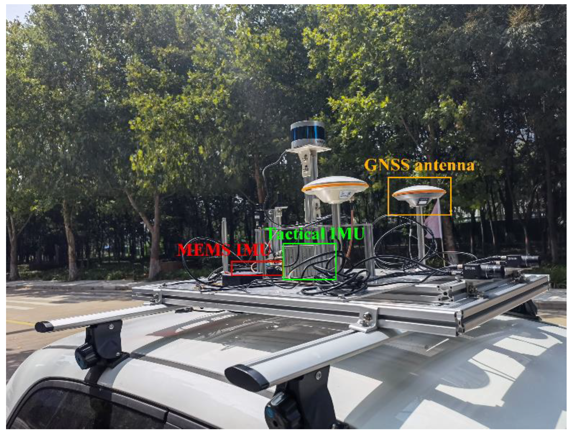

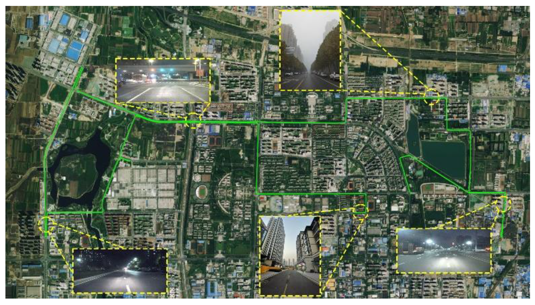

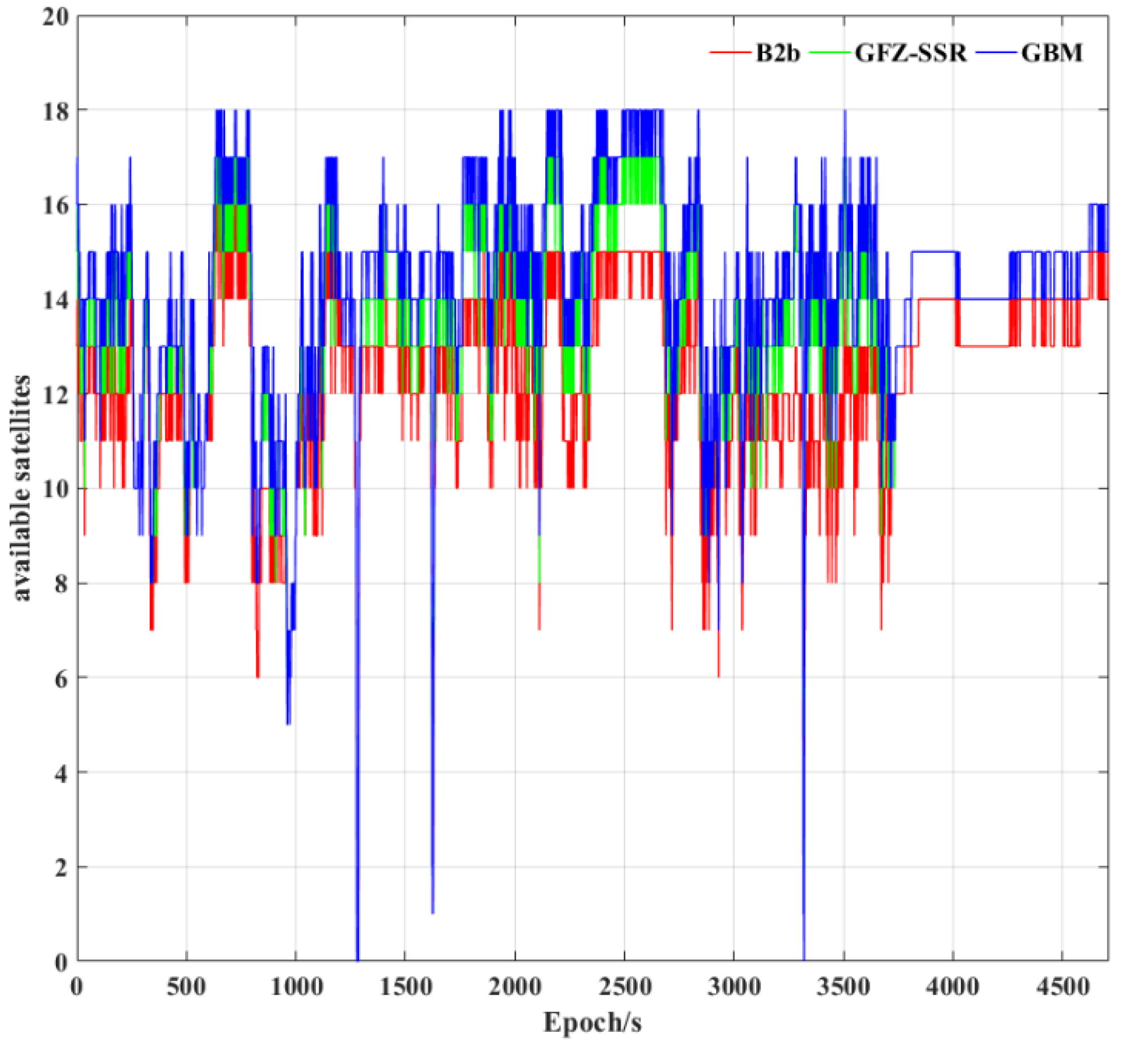

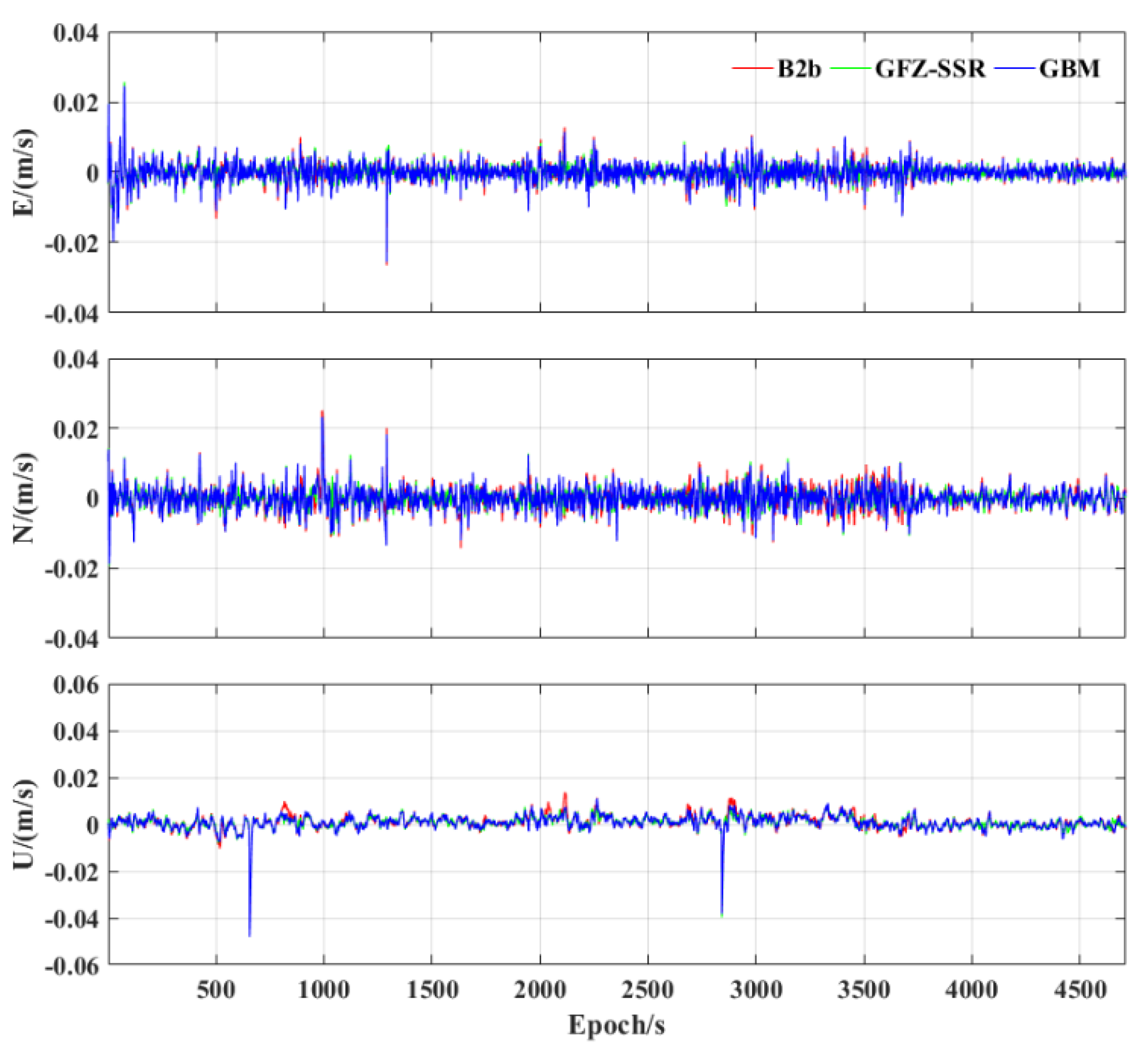

| IMU | Sampling Rates | Accelerometer Bias (mGal) | ||
|---|---|---|---|---|
| SNC300A−DGI | 200 Hz | 0.3 | 50 | 0.05 |
| ADIS−16470 | 100 Hz | 8 | 1300 | 0.34 |
| Parameter | Processing Strategy |
|---|---|
| Satellite systems | BDS−3; GPS |
| Frequency | BDS−3 (C): B1I + B3I; GPS (G): L1 + L2 |
| Sampling rate | 1 Hz |
| Satellite elevation cut−off angle | |
| Receiver clock offsets | Modeled as white noise |
| Tropospheric delay | Using the Saastamoinen model where the residual component is modeled as a random walk process [35] |
| Satellite and receiver antenna phase center offset | igs14.atx |
| Weight for observations | Elevation−dependent weight [36] |
| Inter−system bias | Modeled as a random walk process |
| Biases of accelerometer and gyro | Modeled as a random walk process |
| Quality control strategy | Detection, identification, and adaptation (DIA) [37] |
| Scheme | Available Satellites |
|---|---|
| B2b | 12.34 |
| GFZ−SSR | 13.64 |
| GBM | 14.29 |
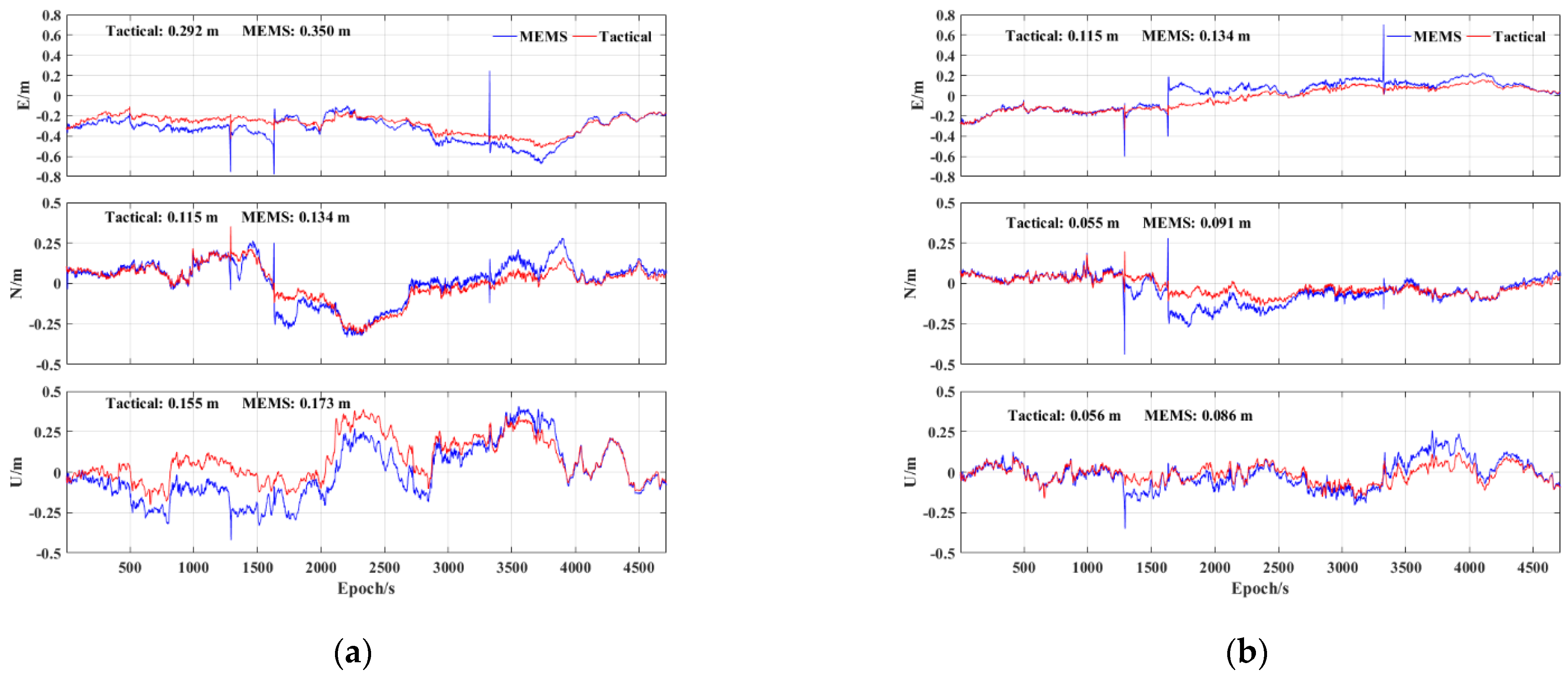
| Scheme | E | N | U | H | 3D |
|---|---|---|---|---|---|
| B2b | 0.292 | 0.115 | 0.155 | 0.314 | 0.350 |
| GFZ−SSR | 0.183 | 0.098 | 0.122 | 0.208 | 0.241 |
| GBM | 0.115 | 0.055 | 0.056 | 0.127 | 0.139 |
| Scheme | E | N | U |
|---|---|---|---|
| B2b | 0.28 | 0.33 | 0.34 |
| GFZ−SSR | 0.25 | 0.29 | 0.30 |
| GBM | 0.27 | 0.30 | 0.31 |
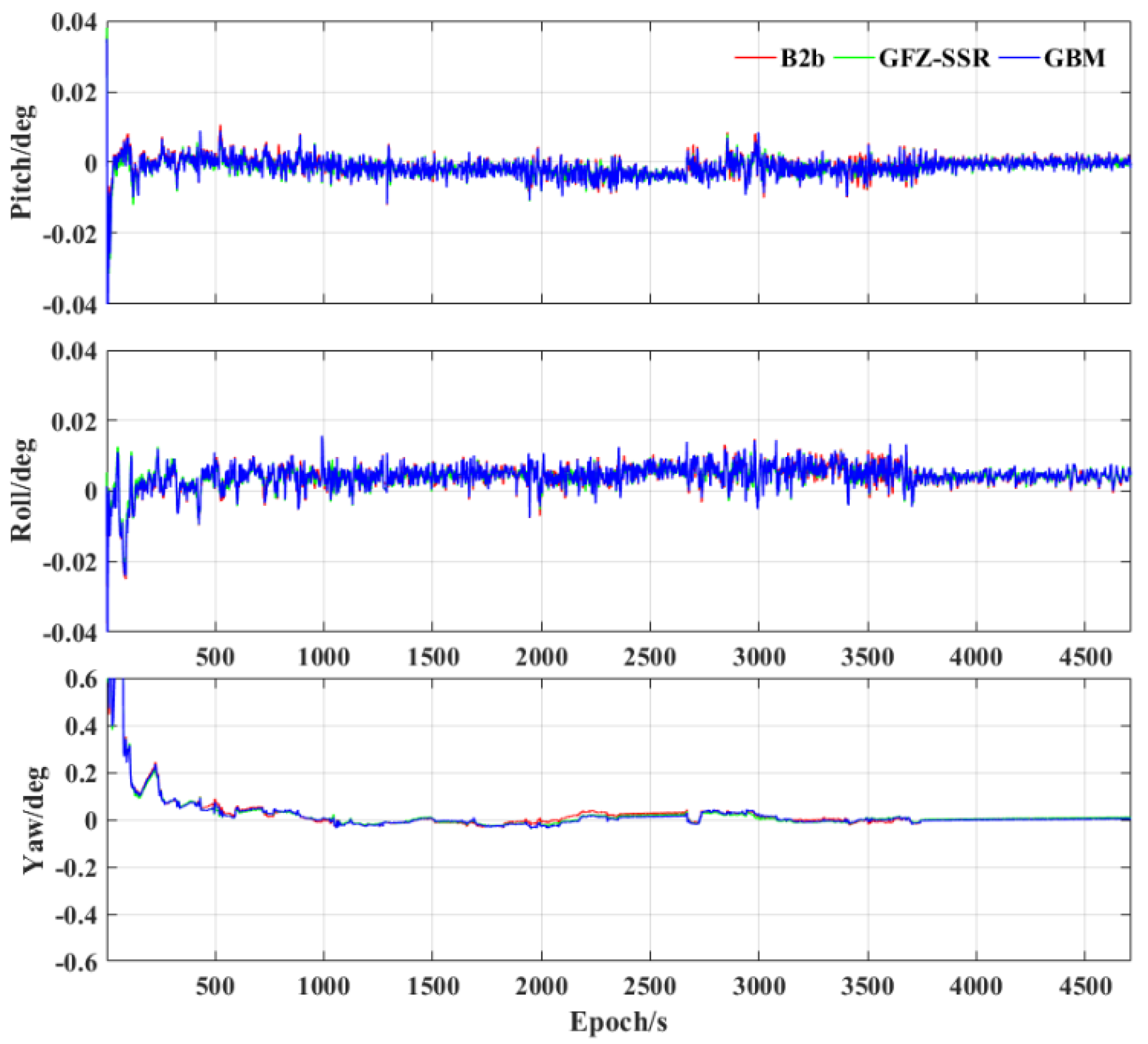
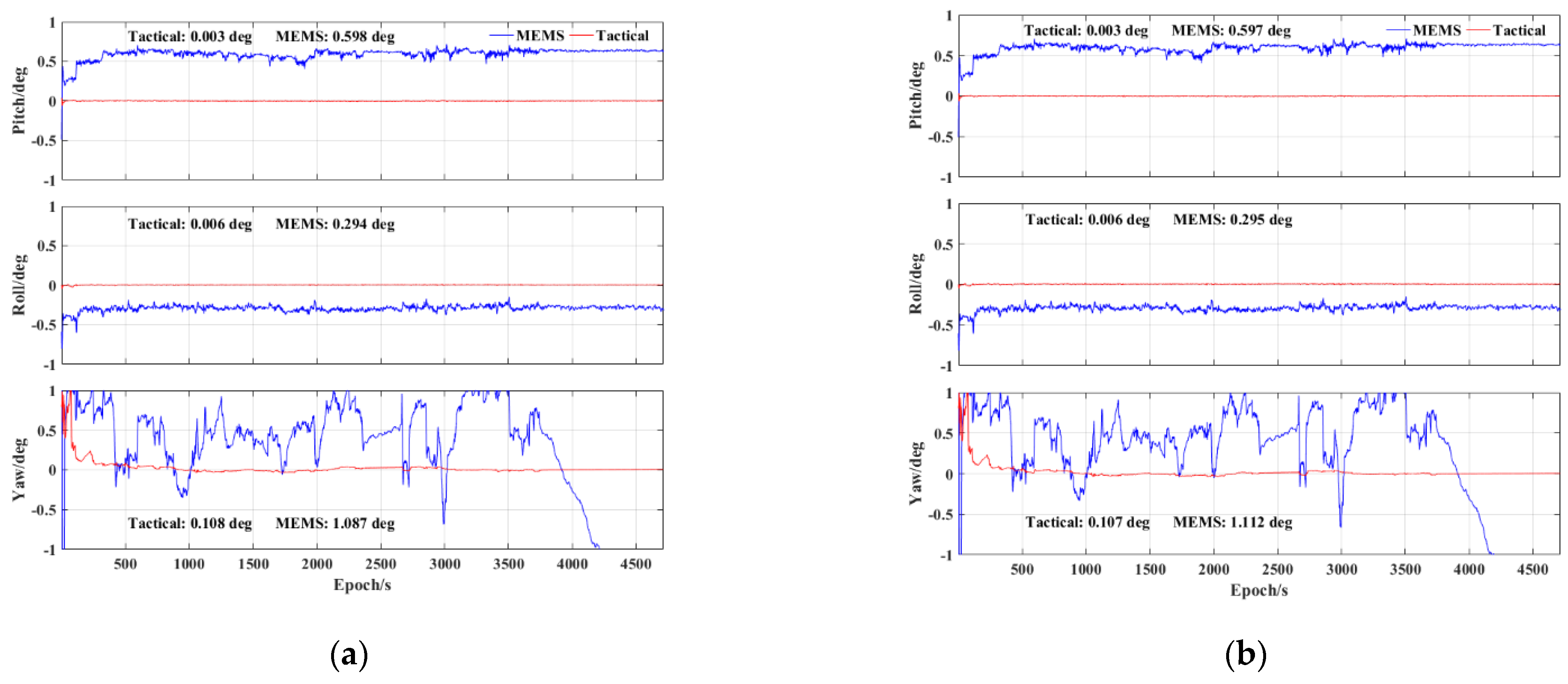
| Scheme | Pitch | Roll | Yaw |
|---|---|---|---|
| B2b | 0.003 | 0.006 | 0.108 |
| GFZ−SSR | 0.003 | 0.005 | 0.107 |
| GBM | 0.003 | 0.006 | 0.107 |
Disclaimer/Publisher’s Note: The statements, opinions and data contained in all publications are solely those of the individual author(s) and contributor(s) and not of MDPI and/or the editor(s). MDPI and/or the editor(s) disclaim responsibility for any injury to people or property resulting from any ideas, methods, instructions or products referred to in the content. |
© 2023 by the authors. Licensee MDPI, Basel, Switzerland. This article is an open access article distributed under the terms and conditions of the Creative Commons Attribution (CC BY) license (https://creativecommons.org/licenses/by/4.0/).
Share and Cite
Lai, L.; Meng, X.; Zhao, D.; Li, X.; Guo, W.; Li, L. PPP/INS Tight Integration with BDS−3 PPP−B2b Service in the Urban Environment. Sensors 2023, 23, 2652. https://doi.org/10.3390/s23052652
Lai L, Meng X, Zhao D, Li X, Guo W, Li L. PPP/INS Tight Integration with BDS−3 PPP−B2b Service in the Urban Environment. Sensors. 2023; 23(5):2652. https://doi.org/10.3390/s23052652
Chicago/Turabian StyleLai, Luguang, Xin Meng, Dongqing Zhao, Xin Li, Wenzhuo Guo, and Linyang Li. 2023. "PPP/INS Tight Integration with BDS−3 PPP−B2b Service in the Urban Environment" Sensors 23, no. 5: 2652. https://doi.org/10.3390/s23052652
APA StyleLai, L., Meng, X., Zhao, D., Li, X., Guo, W., & Li, L. (2023). PPP/INS Tight Integration with BDS−3 PPP−B2b Service in the Urban Environment. Sensors, 23(5), 2652. https://doi.org/10.3390/s23052652


