
An Angular Radial Extended Interaction Amplifier at the W Band


Abstract
1. Introduction
2. Design and Analysis
3. Simulation Performance
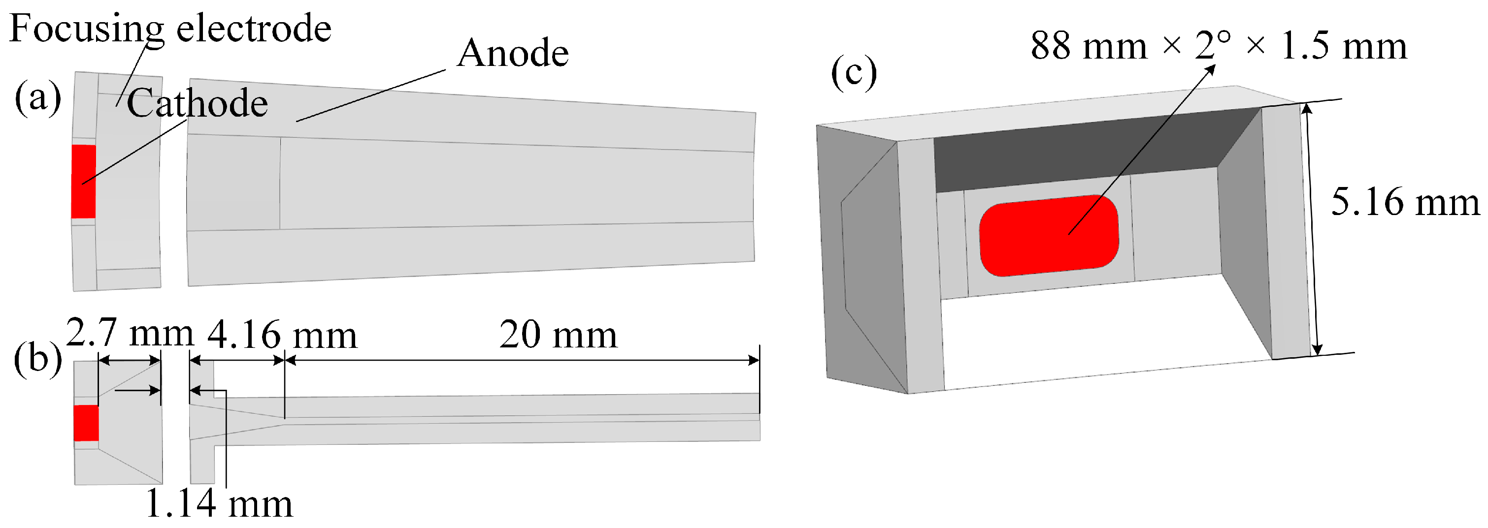
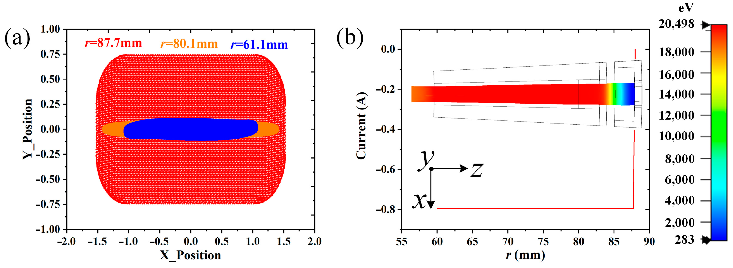
4. Design of the Angular Radial Electron Gun
5. Conclusions
Author Contributions
Funding
Institutional Review Board Statement
Informed Consent Statement
Data Availability Statement
Conflicts of Interest
References
- Arman, M.J. High-power radial klystron oscillator. Proc. SPIE 1995, 2557, 21–31. [Google Scholar]
- Arman, M.J. Radial acceletron, a new low-impedance HPM source. IEEE Trans. Plasma Sci. 1996, 24, 964–969. [Google Scholar] [CrossRef]
- Wu, Z.F.; Wang, Y.Z. Theoretical design and numerical simulations of radial klystron oscillator. HPL Part. Beams 2000, 12, 211–214. [Google Scholar]
- Li, S.F.; Ding, W. A high power microwave radial klystron oscillator with foldaway concentric cylinder resonant cavity. HPL Part. Beams 2003, 15, 909–913. [Google Scholar]
- Zang, J.F.; Liu, Q.X.; Lin, Y.C.; Zhu, J. High frequency characteristics of radial three-cavity transmit time oscillator. HPL Part. Beams 2008, 20, 2046–2050. [Google Scholar]
- Dang, F.C.; Zhang, X.P.; Zhong, H.H.; Zhang, J.; Ju, J.C. A high efficiency Ku-band radial line relativistic klystron amplifier. Phys. Plasmas 2016, 23, 073113. [Google Scholar]
- Chang, Z.W.; Meng, L.; Yin, Y.; Wang, B.; Li, H.L.; Rauf, A.; Ullah, S.; Bi, L.J.; Peng, R.B. Circuit Design of a Compact 5-kV W-Band Extended Interaction Klystron. IEEE Trans. Electron Dev. 2018, 65, 1179–1184. [Google Scholar] [CrossRef]
- Chang, Z.; Shu, G.; Tian, Y.; He, W. Study of the π-Mode Operation in the Extended Interaction Circuit. IEEE Trans. Plasma Sci. 2022, 50, 649–655. [Google Scholar] [CrossRef]
- Naidu, V.B.; Gope, D.; Datta, S.K. Enhancement of Bandwidth of an Extended Interaction Klystron by Symmetric Loading. IEEE Trans. Plasma Sci. 2022, 50, 5018–5022. [Google Scholar]
- Lü, S.; Zhang, C.; Wang, S.; Wang, Y. Stability Analysis of a Planar Multiple-Beam Circuit for a W-Band High-Power Extended-Interaction Klystron. IEEE Trans. Electron Dev. 2015, 62, 3042–3048. [Google Scholar]
- Chen, S.Y.; Ruan, C.J.; Wang, Y.; Zhang, C.Q.; Zhao, D.; Yang, X.D.; Wang, S.Z. Particle-in-Cell Simulation and Optimization of Multigap Extended Output Cavity for a W-Band Sheet-Beam EIK. IEEE Trans. Plasma Sci. 2014, 42, 91–98. [Google Scholar]
- Wang, H.; Xue, Q.; Zhao, D.; Qu, Z.; Ding, H. A Wideband Double-Sheet-Beam Extended Interaction Klystron with Ridge-Loaded Structure. IEEE Trans. Plasma Sci. 2022, 50, 1796–1802. [Google Scholar] [CrossRef]
- Li, R.J.; Ruan, C.J.; Li, S.S.; Zhang, H.F. G-band Rectangular Beam Extended Interaction Klystron Based on Bi-Periodic Structure. IEEE Trans. Terahertz Sci. Tech. 2019, 9, 498–504. [Google Scholar] [CrossRef]
- Li, S.S.; Ruan, C.J.; Fahad, A.K.; Wang, P.P.; Zhang, Z.; He, W.L. Novel Coupling Cavities for Improving the Performance of G-Band Ladder-Type Multigap Extended Interaction Klystrons. IEEE Trans. Plasma Sci. 2020, 48, 1350–1356. [Google Scholar] [CrossRef]
- Hyttinen, M.; Roitman, A.; Horoyski, P.; Deng, H. High Power Pulsed 263 GHz Extended Interaction Amplifier. In Proceedings of the 2020 IEEE 21st International Conference on Vacuum Electronics (IVEC), Monterey, CA, USA, 19–22 October 2020. [Google Scholar]
- Pasour, J.; Wright, E.; Nguyen, K.; Levush, B. Compact, multi-kW sheet beam oscillator at 94 GHz. In Proceedings of the 2014 IEEE 41st International Conference on Plasma Sciences (ICOPS), Washington, DC, USA, 25–29 May 2014. [Google Scholar]
- Pasour, J.; Wright, E.; Nguyen, K.T.; Balkcum, A.; Wood, F.N.; Myers, R.E. Demonstration of a Multikilowatt, Solenoidally Focused Sheet Beam Amplifier at 94 GHz. IEEE Trans. Electron Dev. 2014, 61, 1630–1636. [Google Scholar] [CrossRef]
- Berry, D.; Deng, H.; Dobbs, R.; Horoyski, P.; Hyttinen, M.; Kingsmill, A.; MacHattie, R.; Roitman, A.; Sokol, E.; Steer, B. Practical Aspects of EIK Technology. IEEE Trans. Electron Dev. 2014, 61, 1830–1835. [Google Scholar] [CrossRef]
- Wei, Y.; Li, D.; Zhou, J.; Yang, J.; Yin, L.; Ouyang, J. A High Power W-band Extended Interaction Klystron. In Proceedings of the 2019 International Vacuum Electronics Conference (IVEC), Busan, Republic of Korea, 29 April–1 May 2019. [Google Scholar]
- Rowe, J.E. Nonlinear Electron-Wave Interaction Phenomena; Academic Press: Cambridge, MA, USA, 1965; pp. 72–77. [Google Scholar]
- Li, X.Y.; Wang, Z.L.; He, T.L.; Duan, Z.Y.; Wei, Y.Y.; Gong, Y.B. Study on Radial Sheet Beam Electron Optical System for Miniature Low-Voltage Traveling-Wave Tube. IEEE Trans. Electron Dev. 2017, 64, 3405–3412. [Google Scholar] [CrossRef]
- Dong, Y.; Wang, S.M.; Guo, J.Y.; Wang, Z.L.; Tang, T.; Gong, H.R.; Lu, Z.G.; Duan, Z.Y.; Gong, Y.B. A 0.14 THz Angular Radial Extended Interaction Oscillator. IEEE Trans. Electron Dev. 2022, 69, 1468–1473. [Google Scholar]


| Symbol | Quantity | Dimension (mm) |
|---|---|---|
| r | Initial radius | 20|40|40 |
| θ | Angular angle | 8°|4°|−4° |
| p | Length of period | 0.88 |
| d | Gap width | 0.35 |
| a | Beam tunnel thickness | 0.30 |
| b | Electron beam thickness | 0.20 |
| h | Height of gap | 1.72 |
| t | Coupling cavity width | 0.70 |
| σ (×107 S/m) | −4° (r = 25 mm) | 0° | 8° (r = 35 mm) |
|---|---|---|---|
| 5.8 | 1315 | 1184 | 1253 |
| 3.6 | 1036 | 933 | 987 |
| 2.2 | 810 | 729 | 771 |
| σ (×107 S/m) | −2° EIA (kW) | 0° EIA (kW) | 4° EIA (kW) |
|---|---|---|---|
| 5.8 | 6.24 | 5.94 | 5.30 |
| 3.6 | 5.46 | 5.16 | 4.41 |
| 2.2 | 4.42 | 4.05 | 3.28 |
| Type | Operating Parameters | Output Power & Efficiency |
|---|---|---|
| Pencil beam EIA [7] | 5 kV, 0.2 A, 5.8 × 10⁷ S/m | 67 W, 6.7% |
| Pencil beam EIA [9] | 16 kV, 0.6 A, 5.8 × 10⁷ S/m | 0.9 kW, 9.4% |
| Sheet beam EIA [11] | 75 kV, 4 A, 5.8 × 10⁷ S/m | 50 kW, 16.7% |
| Sheet beam EIA [17] | 20 kV, 4 A | 7.5 kW (peak, tested), 9.4% |
| −2° EIA | 20.5 kV, 1.5 A, 5.8 × 10⁷ S/m | 6.59 kW, 21.4% |
| −2° EIA | 20.5 kV, 0.8 A, 2.2 × 10⁷ S/m | 2.01 kW, 12.3% |
| 0° EIA | 20.5 kV, 0.8 A, 2.2 × 10⁷ S/m | 1.55 kW, 9.5% |
Disclaimer/Publisher’s Note: The statements, opinions and data contained in all publications are solely those of the individual author(s) and contributor(s) and not of MDPI and/or the editor(s). MDPI and/or the editor(s) disclaim responsibility for any injury to people or property resulting from any ideas, methods, instructions or products referred to in the content. |
© 2023 by the authors. Licensee MDPI, Basel, Switzerland. This article is an open access article distributed under the terms and conditions of the Creative Commons Attribution (CC BY) license (https://creativecommons.org/licenses/by/4.0/).
Share and Cite
Dong, Y.; Wang, S.; Guo, J.; Wang, Z.; Gong, H.; Lu, Z.; Duan, Z.; Gong, Y. An Angular Radial Extended Interaction Amplifier at the W Band. Sensors 2023, 23, 3517. https://doi.org/10.3390/s23073517
Dong Y, Wang S, Guo J, Wang Z, Gong H, Lu Z, Duan Z, Gong Y. An Angular Radial Extended Interaction Amplifier at the W Band. Sensors. 2023; 23(7):3517. https://doi.org/10.3390/s23073517
Chicago/Turabian StyleDong, Yang, Shaomeng Wang, Jingyu Guo, Zhanliang Wang, Huarong Gong, Zhigang Lu, Zhaoyun Duan, and Yubin Gong. 2023. "An Angular Radial Extended Interaction Amplifier at the W Band" Sensors 23, no. 7: 3517. https://doi.org/10.3390/s23073517
APA StyleDong, Y., Wang, S., Guo, J., Wang, Z., Gong, H., Lu, Z., Duan, Z., & Gong, Y. (2023). An Angular Radial Extended Interaction Amplifier at the W Band. Sensors, 23(7), 3517. https://doi.org/10.3390/s23073517