
Research on Inertial Navigation and Environmental Correction Indoor Ultra-Wideband Ranging and Positioning Methods


Abstract
:1. Introduction
2. Methods
2.1. Data Collection
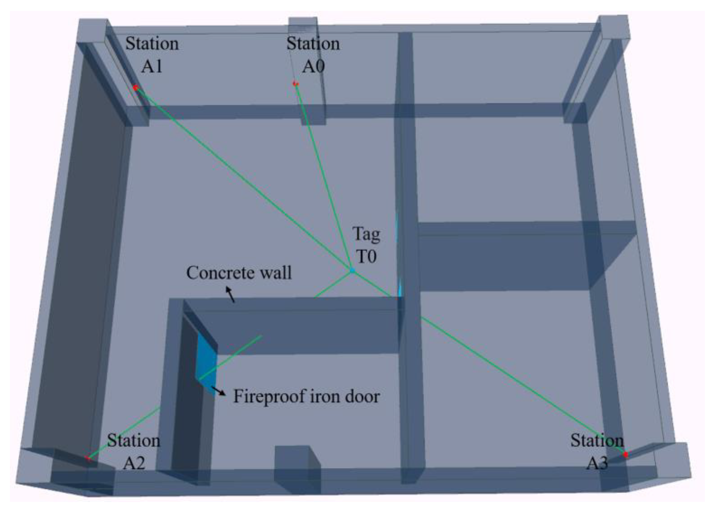
2.1.1. Digital Environment and Construction Method
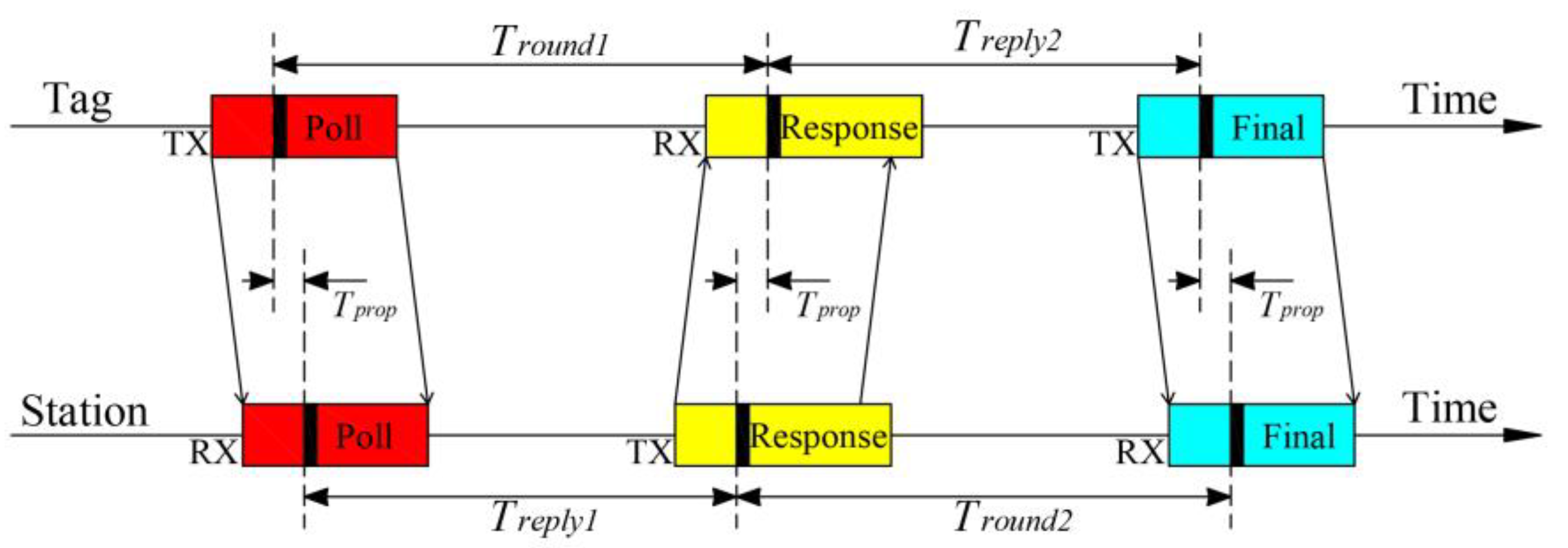
2.1.2. Ranging Information Collection
2.1.3. Sports Information Collection
2.2. Data Processing Methods
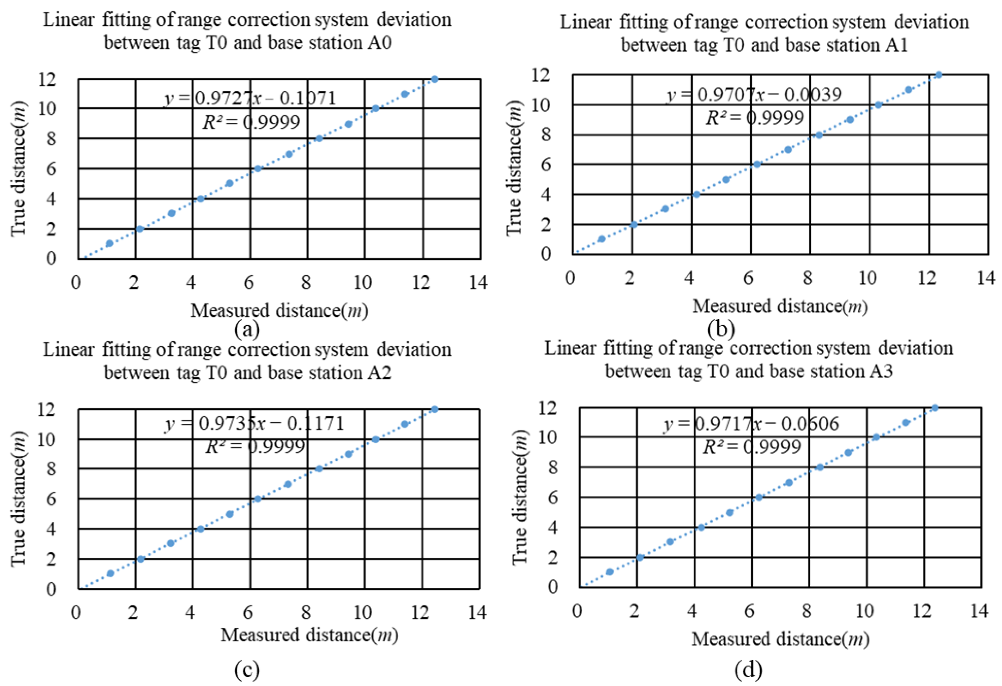
2.2.1. Ranging Data Preprocessing
2.2.2. Distance Filtering Method
2.2.3. Inertial Navigation Data Processing
2.2.4. Ranging Result Correction Based on Digital Environment
- A.
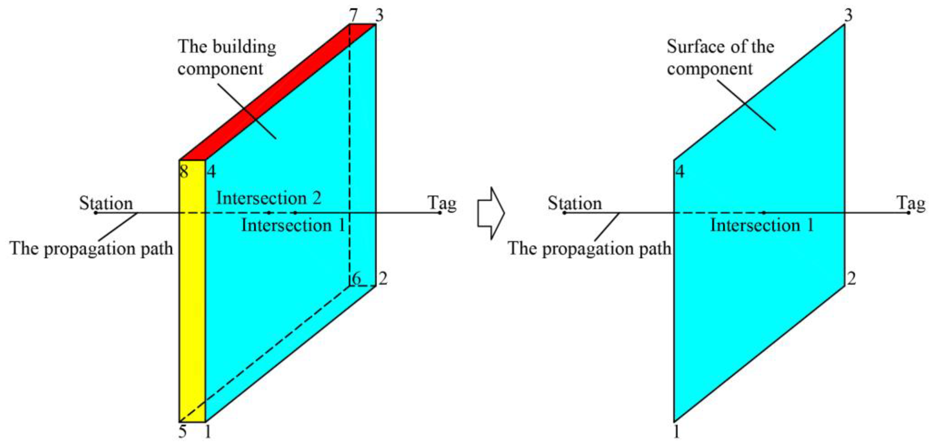
- Method for determining the intersection of the propagation path with building components.
- B.
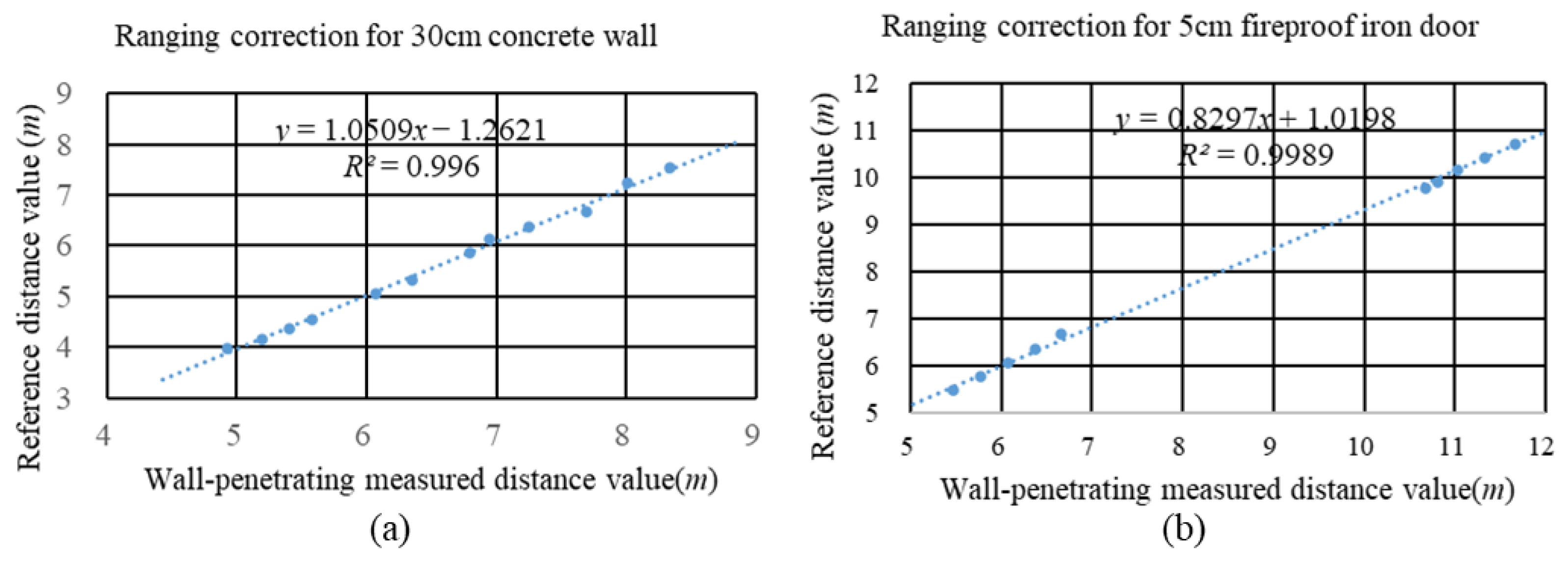
- Ranging Result Correction
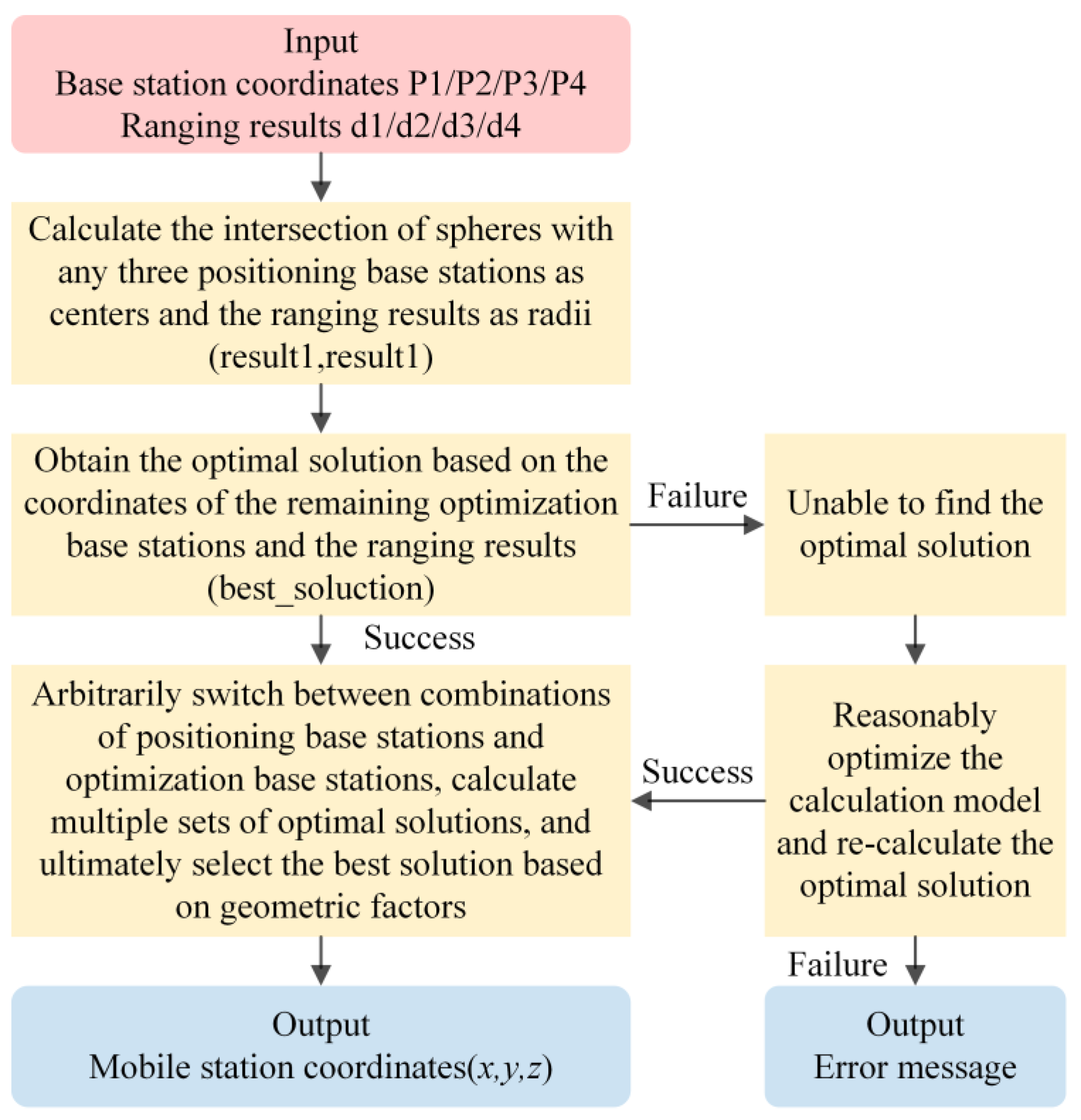
2.3. Spatial Position Estimation
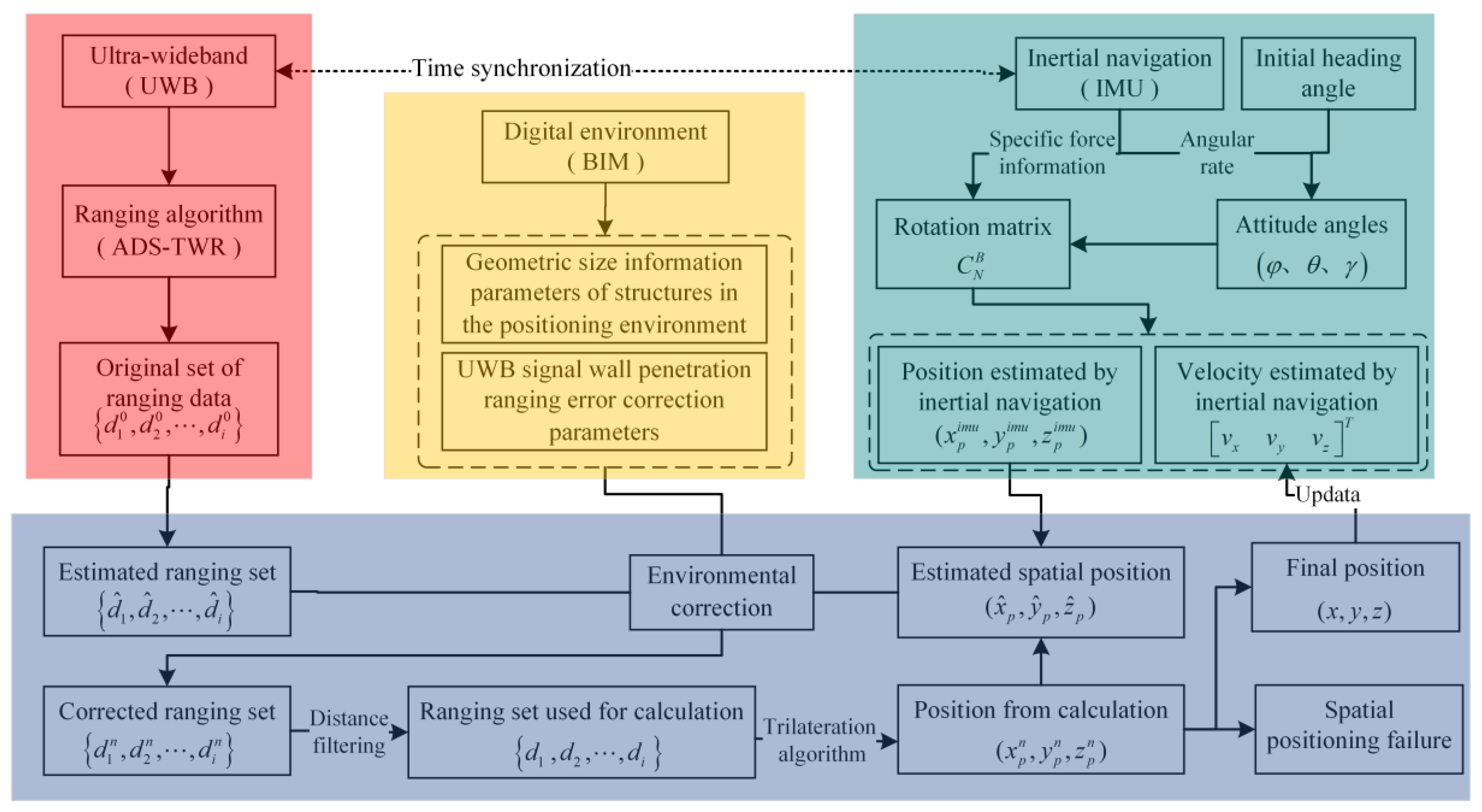
2.4. Integrated Positioning Process Design
- (1)
- Based on the ADS-TWR ranging algorithm, acquire the set of measured distances between the mobile tag and each base station tag, which is then taken as the set of ranging estimates ;
- (2)
- Using inertial navigation data to solve for the mobile tag’s attitude angles //, and derive velocity and spatial position , with the position derived from inertial navigation taken as the estimated spatial position ;
- (3)
- Assume that the UWB signal is emitted by the base station tag at , captured by the mobile tag at , and that the signal propagates in a straight line, acquiring the set of straight line paths between the mobile tag and the ranging base stations;
- (4)
- Obtain the set of geometries in the environment that intersects with all propagation lines; if the set is non-empty, proceed to step (5); otherwise, proceed to step (6);
- (5)
- Acquire all the relevant parameters related to UWB signal penetration for the geometries in set and perform environmental compensation correction on the measured distance , updating the measured distance set ;
- (6)
- Apply distance filtering to the corrected distance set to obtain the set of distances used for spatial position calculation;
- (7)
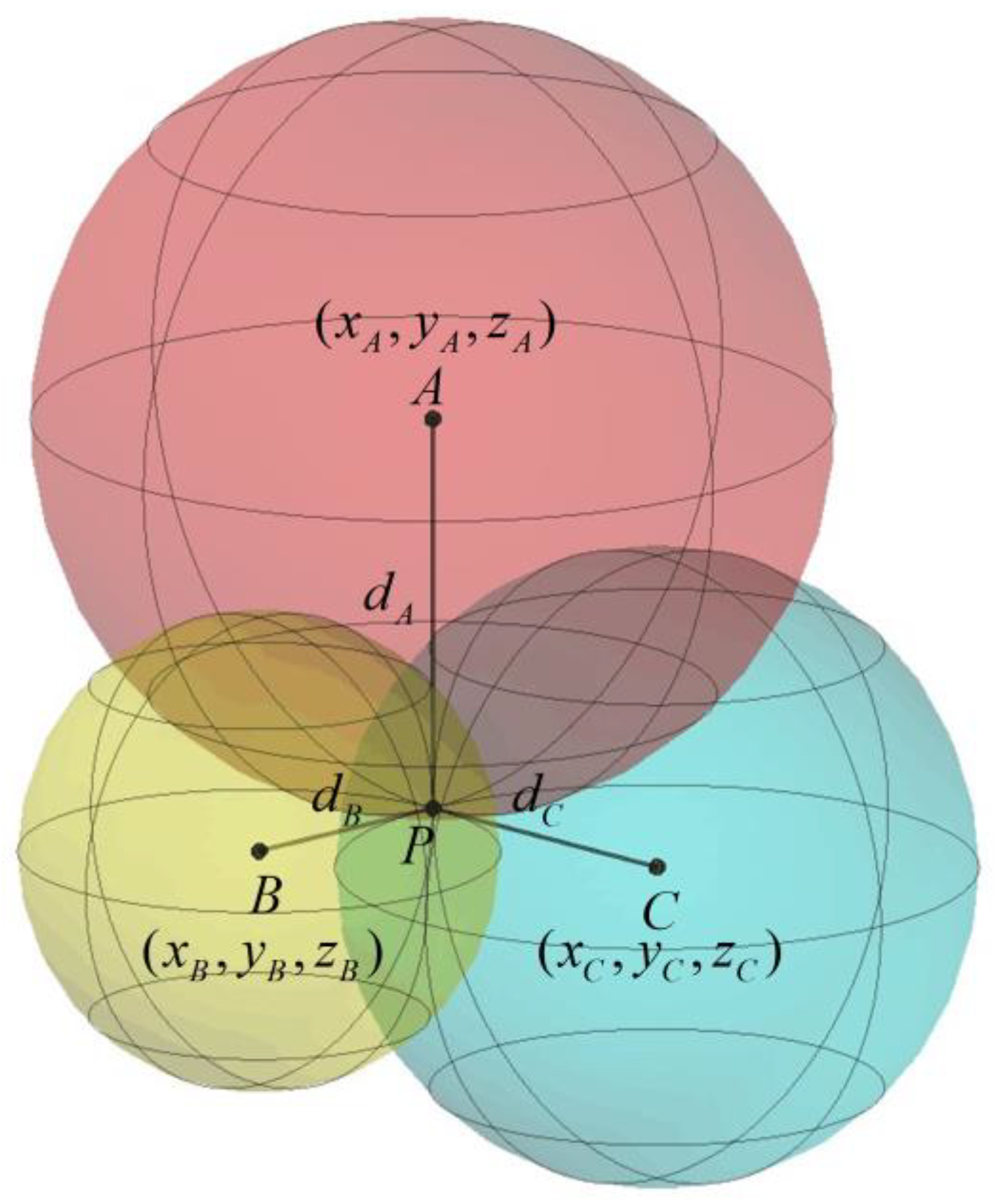
- Based on the coordinates of the base station tags and the distance set , use the trilateration algorithm to obtain the spatial position calculation result , and update the estimated spatial position ;
- (8)
- If the difference between two consecutive estimated spatial positions is less than a threshold, proceed to step (9); if the position difference is greater than the threshold, but the number of iterations is less than the threshold, proceed to step (3); otherwise, positioning fails, proceed to step (10);
- (9)
- We use the final positioning results to update the spatial position of the mobile tag and use consecutive positioning results to update the velocity of the mobile tag and use it as the initial state for the next IMU calculation;
- (10)
- Proceed with the next positioning cycle.
3. Experiments and Results
3.1. Experimental Equipment and Environment
3.2. Dynamic Positioning Experiment and Results
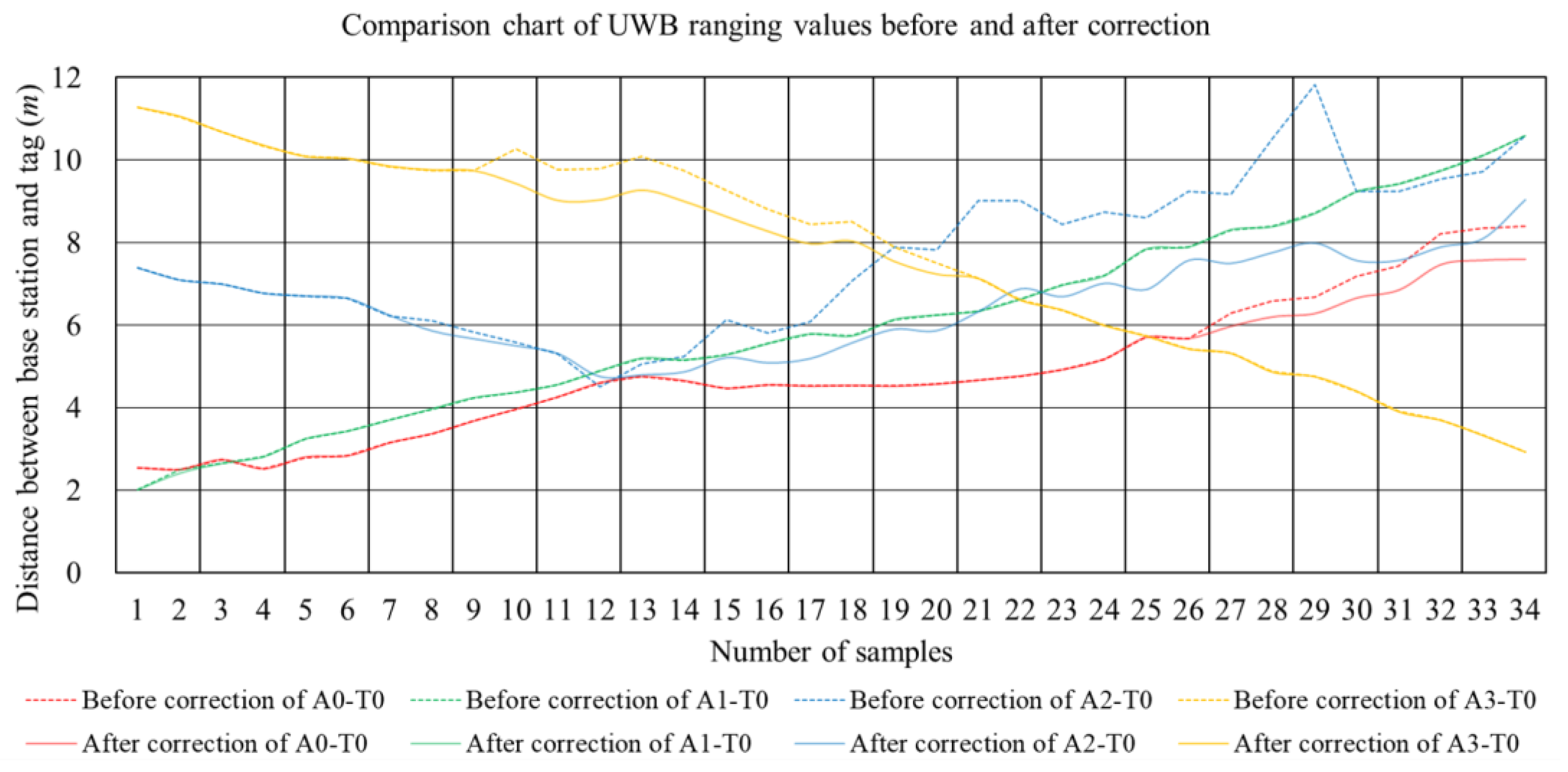
3.2.1. Distance Measurement Results
3.2.2. Positioning Test Results
4. Discussion
4.1. Positioning Result Analysis
4.2. Limitations and Future Work
5. Conclusions
Author Contributions
Funding
Institutional Review Board Statement
Informed Consent Statement
Data Availability Statement
Conflicts of Interest
References
- Yang, Y.; Gao, W.; Guo, S.; Mao, Y.; Yang, Y. Introduction to BeiDou-3 navigation satellite system. Navigation 2019, 66, 7–18. [Google Scholar] [CrossRef]
- Liu, T.; Xu, A.; Sui, X. Application of UWB/INS combination in indoor navigation and positioning. Acta Geod. Cartogr. Sin. 2016, 41, 162–166. [Google Scholar] [CrossRef]
- Alarifi, A.; Al-Salman, A.; Alsaleh, M.; Alnafessah, A.; Al-Hadhrami, S.; Al-Ammar, M.A.; Al-Khalifa, H.S. Ultra wideband indoor positioning technologies: Analysis and recent advances. Sensors 2016, 16, 707. [Google Scholar] [CrossRef] [PubMed]
- Xu, A.; Liu, T.; Sui, X.; Wang, C. Indoor positioning and attitude determination method based on UWB/INS tightly coupled. J. Navig. Position. 2017, 5, 14–19. [Google Scholar] [CrossRef]
- Peng, X.; Chen, R.; Yu, K.; Guo, G.; Ye, F.; Xue, W. A new Wi-Fi dynamic selection of nearest neighbor localization algorithm based on RSS characteristic value extraction by hybrid filtering. Meas. Sci. Technol. 2020, 32, 034003. [Google Scholar] [CrossRef]
- Zhu, Z.; Jiang, W.; Zhang, G.; Zhu, Y.; Zhu, C. Indoor WiFi location algorithm based on RSSI. Comput. Eng. Des. 2020, 41, 2958–2962. [Google Scholar] [CrossRef]
- Ye, F.; Chen, R.; Guo, G.; Peng, X.; Liu, Z.; Huang, L. A low-cost single-anchor solution for indoor positioning using BLE and inertial sensor data. IEEE Access 2019, 7, 162439–162453. [Google Scholar] [CrossRef]
- Faragher, R.; Harle, R. Location Fingerprinting with Bluetooth Low Energy Beacons. IEEE J. Sel. Areas Commun. 2015, 33, 2418–2428. [Google Scholar] [CrossRef]
- Li, N.; Becerik-Gerber, B. Performance-based evaluation of RFID-based indoor location sensing solutions for the built environment. Adv. Eng. Inform. 2011, 25, 535–546. [Google Scholar] [CrossRef]
- Ma, Y.; Tian, C.; Jiang, Y. A multitag cooperative localization algorithm based on weighted multidimensional scaling for passive UHF RFID. IEEE Internet Things J. 2019, 6, 6548–6555. [Google Scholar] [CrossRef]
- Zhu, L. Research on RFID Collaboration Localization Based on Multi-Data Fusion. Ph.D. Thesis, Nanjing University of Posts and Telecommunications, Nanjing, China, 2020. [Google Scholar] [CrossRef]
- Medina, C.; Segura, J.C.; De la Torre, A. Ultrasound indoor positioning system based on a low-power wireless sensor network providing sub-centimeter accuracy. Sensors 2013, 13, 3501–3526. [Google Scholar] [CrossRef] [PubMed]
- Filippoupolitis, A.; Oliff, W.; Loukas, G. Bluetooth low energy based occupancy detection for emergency management. In Proceedings of the 2016 15th International Conference on Ubiquitous Computing and Communications and 2016 International Symposium on Cyberspace and Security (IUCC-CSS), Granada, Spain, 14–16 December 2016; pp. 31–38. [Google Scholar] [CrossRef]
- Tekler, Z.D.; Low, R.; Yuen, C.; Blessing, L. Plug-Mate: An IoT-based occupancy-driven plug load management system in smart buildings. Build. Environ. 2022, 223, 109472. [Google Scholar] [CrossRef]
- Balaji, B.; Xu, J.; Nwokafor, A.; Gupta, R.; Agarwal, Y. Sentinel: Occupancy based HVAC actuation using existing WiFi infrastructure within commercial buildings. In Proceedings of the 11th ACM Conference on Embedded Networked Sensor Systems, Roma, Italy, 11–15 November 2013; pp. 1–14. [Google Scholar] [CrossRef]
- Low, R.; Tekler, Z.D.; Cheah, L. An end-to-end point of interest (POI) conflation framework. ISPRS Int. J. Geo-Inf. 2021, 10, 779. [Google Scholar] [CrossRef]
- Tekler, Z.D.; Chong, A. Occupancy prediction using deep learning approaches across multiple space types: A minimum sensing strategy. Build. Environ. 2022, 226, 109689. [Google Scholar] [CrossRef]
- Zhu, Z.; Ding, S.; Xu, S. Airborne Equipment Maintenance Management System Based on RFID Technology. Adv. Aeronaut. Sci. Eng. 2022, 13, 144–150. [Google Scholar] [CrossRef]
- Li, Q.; Wu, Z.; Li, J.; Sun, W.; Wang, J. NLOS error elimination algorithm based on modified Kalman filtering. J. Electron. Meas. Instrum. 2015, 29, 1513–1519. [Google Scholar] [CrossRef]
- Fu, J.; Xu, D.; Fu, Y. Application of an adaptive UKF in UWB indoor positioning. Bull. Surv. Mapp. 2019, S1, 12–17. [Google Scholar] [CrossRef]
- Huang, B.; Li, W. Location algorithm based on particle filtering and maximum likelihood for TDOA under LOS_ NLOS conditions. Comput. Simul. 2022, 39, 481–484. [Google Scholar]
- Huerta, J.; Vidal, J.; Giremus, A.; Tourneret, J. Joint particle filter and UKF position tracking in severe non-line-of-sight situations. IEEE J. Sel. Top. Signal Process. 2009, 3, 874–888. [Google Scholar] [CrossRef]
- Mao, K.; Wu, J.; Jin, H.; Miao, C.; Xiao, M.; Chen, Q. Indoor localization algorithm for NLOS environment. Acta Electron. Sin. 2016, 44, 1174–1179. [Google Scholar] [CrossRef]
- Yang, X. Research on localization algorithm based on TOA-AOA data fusion. Electron. Meas. Technol. 2020, 43, 104–108. [Google Scholar] [CrossRef]
- Lee, J.; Scholtz, R. Ranging in a dense multipath environment using an UWB radio link. IEEE J. Sel. Areas Commun. 2002, 20, 1677–1683. [Google Scholar] [CrossRef]
- Wu, S.; Zhang, Q.; Zhang, N. A NLOS error mitigation method for UWB ranging in dense Multi-path environments. Acta Electron. Sin. 2008, 36, 39–45. [Google Scholar]
- Li, C.; Zhen, J.; Zhun, H.; Sun, Y.; Sheng, K. UWB high precision positioning algorithm in complex environment. Sci. Surv. Mapp. 2020, 45, 4–10. [Google Scholar] [CrossRef]
- Zhu, W.; Zhao, R.; Zhang, H.; Lu, J.; Zhang, Z.; Wei, B.; Fan, Y. Improved Indoor Positioning Model Based on UWB/IMU Tight Combination with Double-Loop Cumulative Error Estimation. App. Sci. 2023, 13, 10046. [Google Scholar] [CrossRef]
- Wang, P.; Hou, Z. Indoor dynamic positioning algorithm fused with UWB and IMU. Electron. Meas. Technol. 2023, 46, 76–83. [Google Scholar] [CrossRef]
- Meng, J.; Zhang, Q.; Zhang, N.; Zhang, T.; Ma, L. Research on IR-UWB through wall ranging error. J. Harbin Inst. Technol. 2011, 43, 84–88. [Google Scholar] [CrossRef]
- Neirynck, D.; Luk, E.; McLaughlin, M. An alternative double-sided two-way ranging method, M.M. In Proceedings of the 2016 13th Workshop on Positioning, Navigation and Communications (WPNC), Bremen, Germany, 19–20 October 2016; pp. 1–4. [Google Scholar] [CrossRef]
- Alavi, B.; Alsindi, N.; Pahlavan, K. UWB channel measurements for accurate indoor localization. In Proceedings of the MILCOM 2006 IEEE Military Communications Conference, Washington, DC, USA, 23–25 October 2006; pp. 1–7. [Google Scholar] [CrossRef]
- Bellusci, G.; Janssen, G.J.M.; Yan, J.; Tiberius, C.C.J.M. Modeling distance and bandwidth dependency of TOA-based UWB ranging error for positioning. J. Electr. Comput. Eng. 2009, 2009, 468597. [Google Scholar] [CrossRef]
- Liu, M.; Cai, Y.; Zhang, L.; Wang, Y. Attitude Estimation Algorithm of Portable Mobile Robot Based on Complementary Filter. Micromachines 2021, 12, 1373. [Google Scholar] [CrossRef]
- Li, Q.; Zhang, Y.P. Waveform distortion and performance of impulse radio with realistic antennas in deterministic multipath channels. In Proceedings of the VTC Spring 2008-IEEE Vehicular Technology Conference, Singapore, 11–14 May 2008; pp. 260–264. [Google Scholar] [CrossRef]
- Doukhnitch, E.; Salamah, M.; Ozen, E. An efficient approach for trilateration in 3D positioning. Comput. Commun. 2008, 31, 4124–4129. [Google Scholar] [CrossRef]


| Error | LOS Environment | Including NLOS Environment | ||||
|---|---|---|---|---|---|---|
| Maximum Value | Minimum Value | Average Value | Maximum Value | Minimum Value | Average Value | |
| X-axis (m) | 0.091 | 0.009 | 0.053 | 1.700 | 0.03 | 0.683 |
| Y-axis (m) | 0.270 | 0.141 | 0.199 | 1.531 | 0.007 | 0.704 |
| Z-axis (m) | 1.042 | 0.253 | 0.639 | 2.336 | 0.921 | 1.628 |
| XY plane (m) | 0.270 | 0.142 | 0.208 | 2.288 | 0.291 | 0.998 |
| Error | LOS Environment | Including NLOS Environment | ||||
|---|---|---|---|---|---|---|
| Maximum Value | Minimum Value | Average Value | Maximum Value | Minimum Value | Average Value | |
| X-axis (m) | 0.092 | 0.008 | 0.051 | 1.700 | 0.031 | 0.684 |
| Y-axis (m) | 0.169 | 0.041 | 0.091 | 1.431 | 0.109 | 0.612 |
| Z-axis (m) | 1.023 | 0.003 | 0.501 | 2.335 | 0.914 | 1.627 |
| XY plane (m) | 0.169 | 0.044 | 0.108 | 2.222 | 0.22 | 0.933 |
| Error | LOS Environment | Including NLOS Environment | ||||
|---|---|---|---|---|---|---|
| Maximum Value | Minimum Value | Average Value | Maximum Value | Minimum Value | Average Value | |
| X-axis (m) | 0.198 | 0.061 | 0.104 | 0.878 | 0.009 | 0.219 |
| Y-axis (m) | 0.187 | 0.015 | 0.073 | 0.493 | 0.003 | 0.203 |
| Z-axis (m) | 0.620 | 0.048 | 0.404 | 2.177 | 0.007 | 0.703 |
| XY plane (m) | 0.221 | 0.065 | 0.134 | 0.976 | 0.071 | 0.319 |
Disclaimer/Publisher’s Note: The statements, opinions and data contained in all publications are solely those of the individual author(s) and contributor(s) and not of MDPI and/or the editor(s). MDPI and/or the editor(s) disclaim responsibility for any injury to people or property resulting from any ideas, methods, instructions or products referred to in the content. |
© 2024 by the authors. Licensee MDPI, Basel, Switzerland. This article is an open access article distributed under the terms and conditions of the Creative Commons Attribution (CC BY) license (https://creativecommons.org/licenses/by/4.0/).
Share and Cite
Han, C.; Xue, S.; Long, L.; Xiao, X. Research on Inertial Navigation and Environmental Correction Indoor Ultra-Wideband Ranging and Positioning Methods. Sensors 2024, 24, 261. https://doi.org/10.3390/s24010261
Han C, Xue S, Long L, Xiao X. Research on Inertial Navigation and Environmental Correction Indoor Ultra-Wideband Ranging and Positioning Methods. Sensors. 2024; 24(1):261. https://doi.org/10.3390/s24010261
Chicago/Turabian StyleHan, Chunhua, Shunbiao Xue, Li Long, and Xiongquan Xiao. 2024. "Research on Inertial Navigation and Environmental Correction Indoor Ultra-Wideband Ranging and Positioning Methods" Sensors 24, no. 1: 261. https://doi.org/10.3390/s24010261