3.1. Spatial Mapping and Perceptual Characteristics of the Index Finger
The study introduces an interaction method aimed at simplifying navigation tasks by centering on the right hand, specifically the index finger as the tactile perception area, to establish a body-based spatial reference system that leverages human innate proprioception to reduce potential cognitive load [
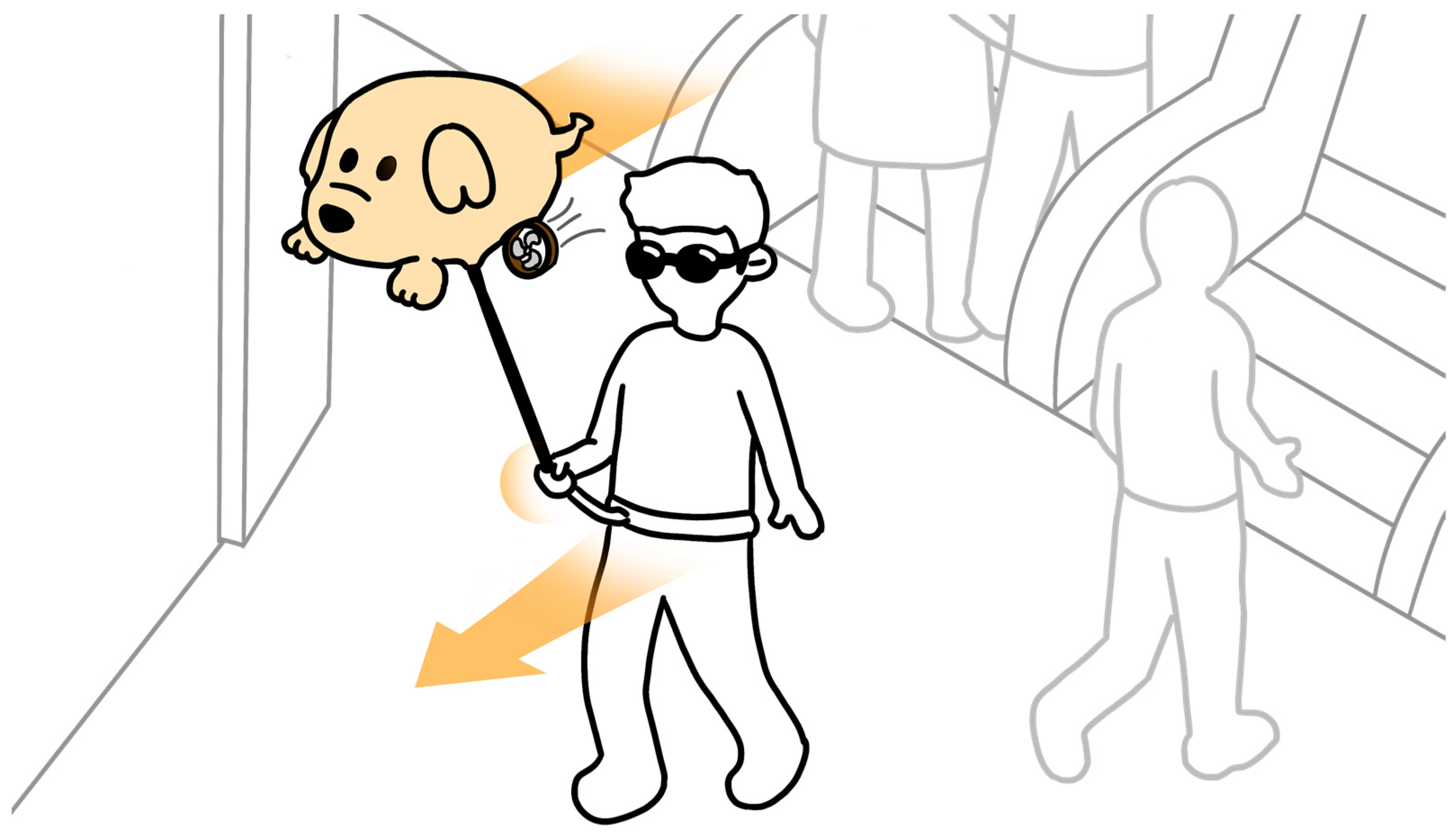
48]. The specific implementation details, as shown in
Figure 2a, show the right hand in a gripping position, placed in front of the body, holding the assistive handle of the Aerial Guide Dog, and maintaining the spatial relationship of the right hand relative to the body. When the Aerial Guide Dog conveys directional information to the right index finger, the wrist must rotate in the prompted direction, allowing directional information to be obtained by perceiving the change in the right wrist’s position relative to the body.
The spatial reference system utilizes human proprioception, which mainly includes joint position sense and joint static awareness, playing a crucial role in understanding spatial environments. Joint position sense is used to ensure that users are aware of the relative position between their right index finger and their body, while joint static awareness ensures that users can determine this positional relationship even when stationary. This inherent bodily spatial positioning ability enables users to instinctively grasp the positioning and interconnection of limb joints relative to the entire body [
49]. Furthermore, considering the successful performance of past projects, assistive devices for the blind that use proprioceptive correspondence as a fundamental element can provide a more natural method of orientation interaction [
12].
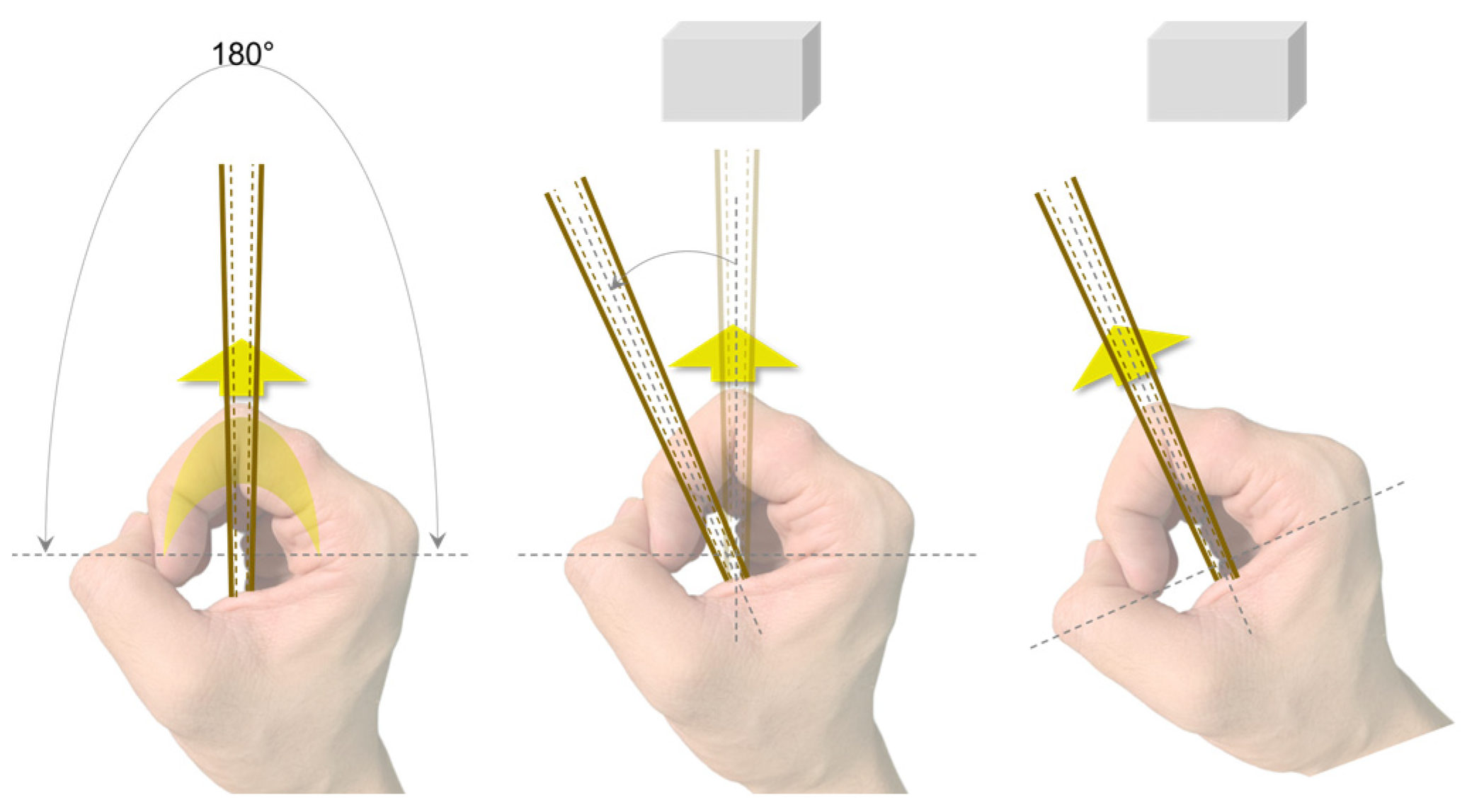
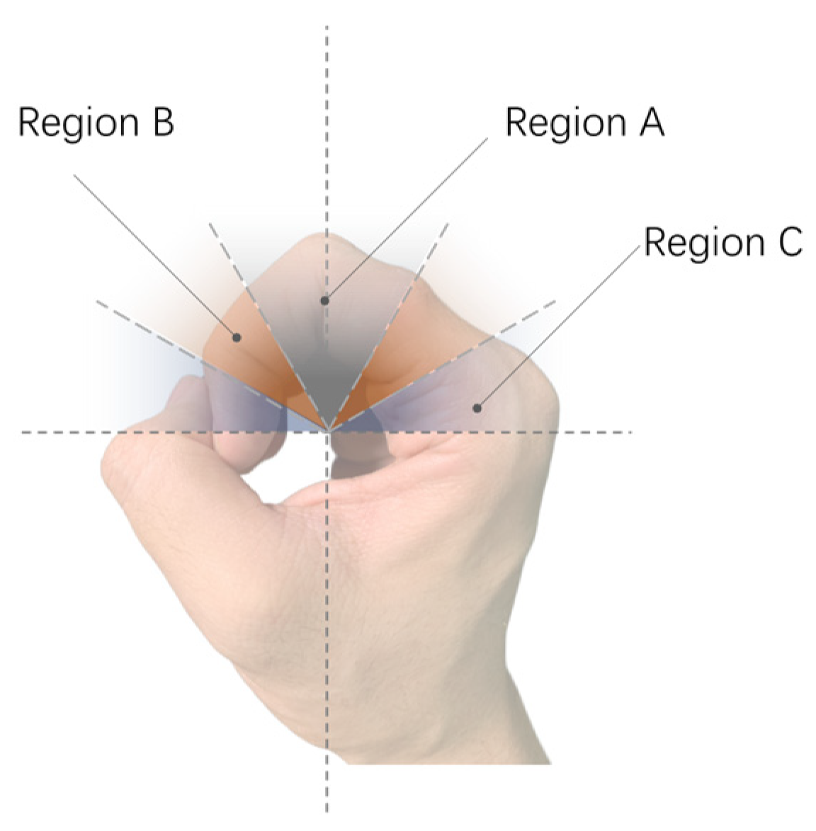
This method involves creating a spatial positioning system centered around the index finger: the interval from the second joint to the fingertip corresponds to the spatial mapping of the 90° to 0° area directly in front of the user, while the interval from the second joint to the base of the finger corresponds to the 90° to 180° area in front of the user, as illustrated in
Figure 2. Based on this, users can obtain directional information within the 0° to 180° area directly in front of them.
Additionally, the finger tips and fleshy inside parts of the fingers are the most densely populated area for sensory organs, with five types of receptors distributed beneath the finger pads, including Ruffini corpuscles, Meissner corpuscles, Pacinian corpuscles, Merkel discs, and free nerve endings. Therefore, using the these areas of the fingers as the receptive part results in clearer perception of tactile information [
48]. Moreover, the continuous traction force stimulation transmitted to the fingers during the use of the Aerial Guide Dog for indoor navigation falls under the kinesthetic category [
45,
50], where the effectiveness of guidance based on continuous traction force feedback is primarily attributed to Ruffini corpuscles as the receptors for traction force stimulation [
51]. The slow-adapting nature of Ruffini corpuscles ensures that the sensation of the traction force does not diminish immediately when the stimulus is continuously applied [
47,
48,
49] so that users can continuously perceive the transmitted traction force stimuli and its directional information through the fingers, thereby ensuring the effectiveness of continuous navigation.
It is felt that this approach simplifies cognitive processing by creating an angular mapping between the joint of the index finger and the user’s frontal area, using the index finger pulp as the tactile receptive area for directly receiving directional signals, which reduces the cognitive effort required to understand and interpret the navigation signals [
19,
52].
3.2. Wearable Tactile Prototype and Its Interaction Methodology
To implement traction force feedback, we utilize servo motors and a helium balloon aerostat drone to build a simple, intuitive, and low-cost prototype design to validate the feasibility of mapping traction force directional signals to a spatial reference system established based on the user’s body.
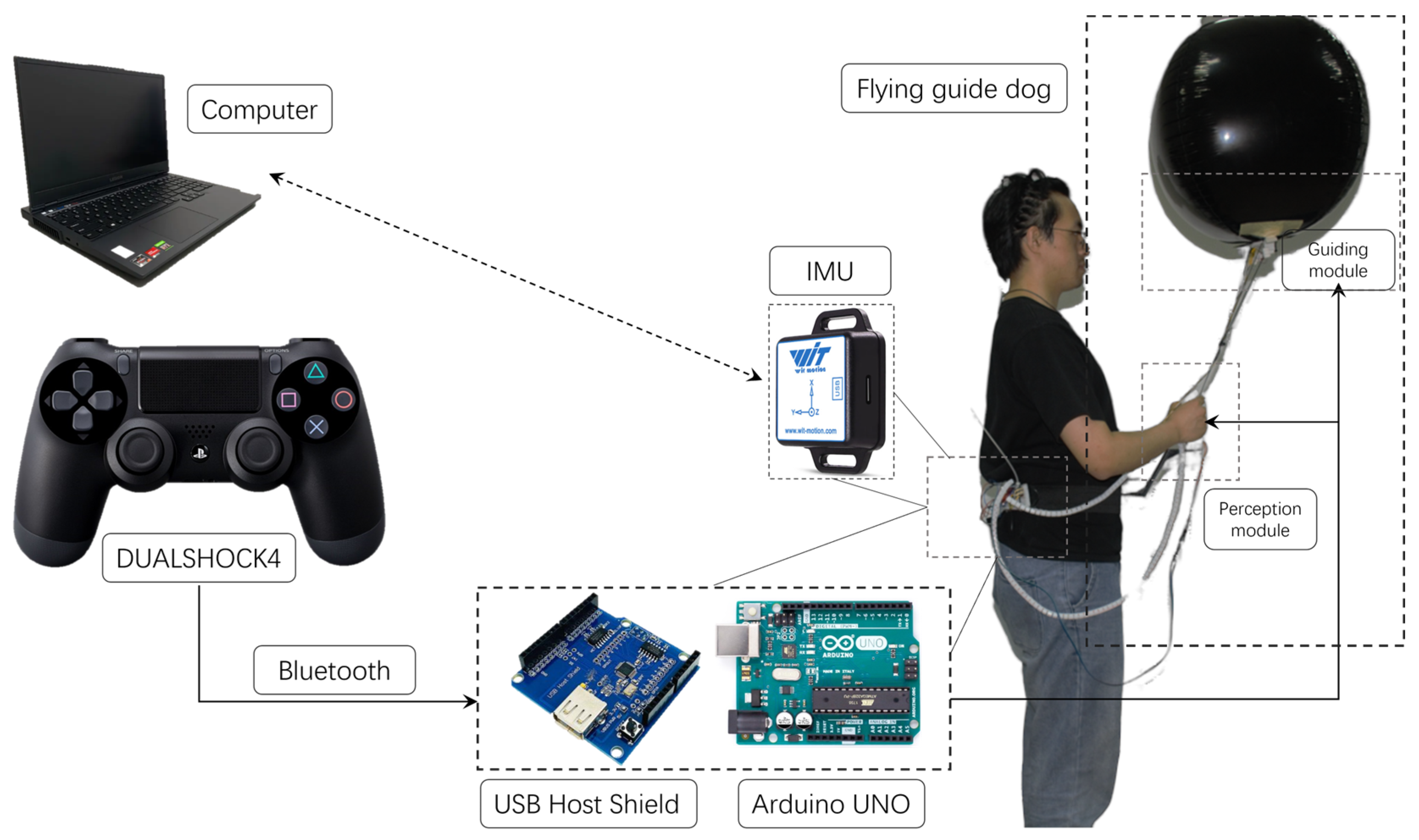
The prototype system developed comprises three main modules:
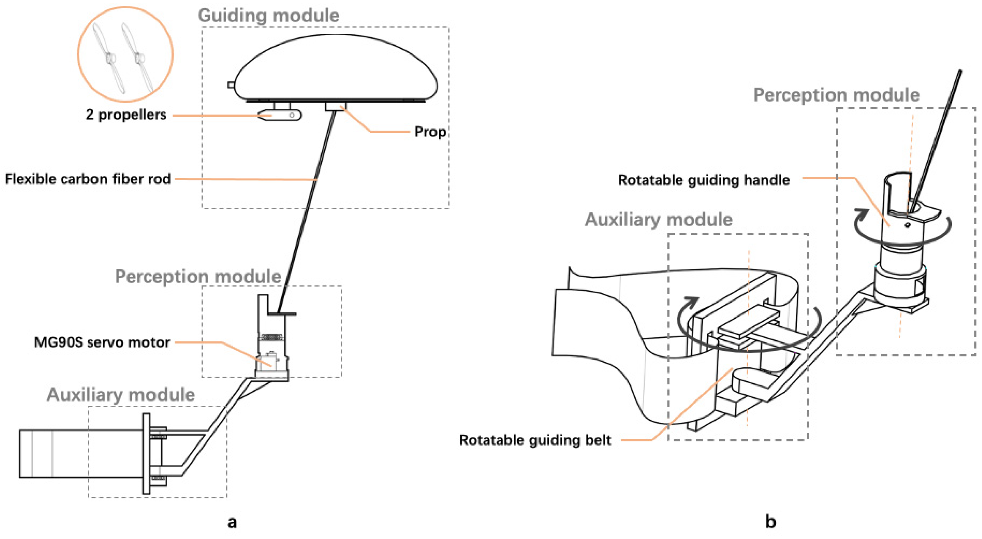
The guidance module: as shown in
Figure 3a, the main component is a 32-inch aluminum film balloon filled with helium (here referred to as the helium balloon aerostat drone). A 3D-printed prop acts as a connecting element, securing the helium balloon aerostat drone to a flexible carbon fiber rod. The bottom of the helium balloon aerostat drone is also equipped with 2 propellers, which generate horizontal thrust when rotating, propelling the aerostat drone forward.
The perception module: as shown in
Figure 3a, the MG90S servo motor inside the perception module is connected to the flexible carbon fiber rod, controlling its angular position to convey the direction of movement to the user’s fingers. As depicted in
Figure 3b, the exterior of the perception module features a rotatable 3D-printed handle, which the user grips to assist in adjusting wrist rotation. Additionally, the handle is embedded with a vibration motor, providing extra tactile feedback for each movement of the rod.
The auxiliary module: as shown in
Figure 3b, the auxiliary module primarily consists of a servo motor, a 3D-printed support structure, and a waist belt. It is designed to assist users in adjusting their body orientation.
To implement traction force feedback, we utilize servo motors and a helium balloon aerostat drone to construct a simple, intuitive, and low-cost prototype design to validate the feasibility of mapping traction force directional signals to a spatial reference system established based on the user’s body.
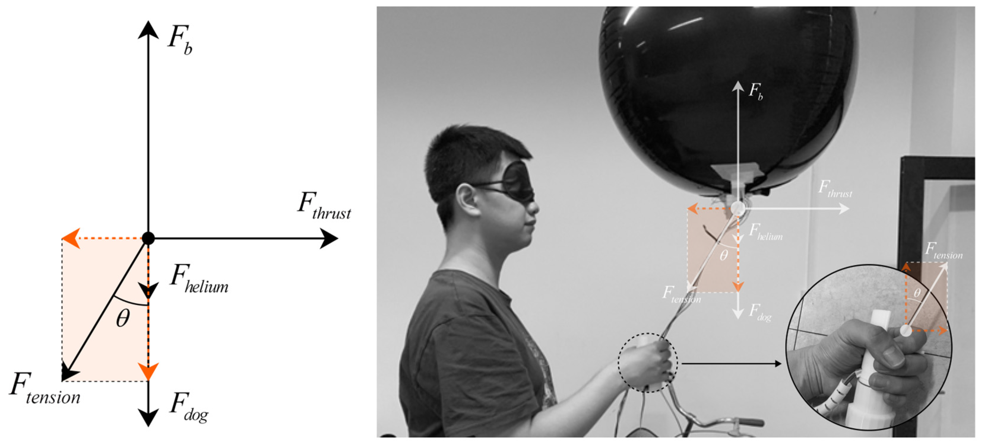
The overall force analysis of the Aerial Guide Dog prototype during operation is shown in
Figure 4 through the upward buoyant force
, where
are the density of air, the volume of the balloon, and the acceleration of gravity, respectively.
Apparently, the downward gravity composed of the weight of the Aerial Guide Dog including the weight of helium can be expressed as .
Thus, given the overall status of floating or hovering in the air, the balance between buoyancy and downward gravity can be expressed as .
Given the density of helium , it is not hard to find that .
In reality, by inflating more helium in the balloon, the is slightly greater than , causing a tender upward force on the rod where the other end is held by human hands.
A thrust force can be generated by the dual motors to drive the Aerial Guide Dog towards different directions. Consequently, the force is transmitted via the rod for the user to follow.
Ideally, when the Aerial Guide Dog is moving horizontally and the rod is at an angle with respect to the vertical direction, the tension in the string can be decomposed into two components, and , where the former is the vertical component counterbalanced by the buoyancy and weight of the balloon and the latter is the horizontal component that the user feels as a traction force.
The magnitude of this force will depend on the difference between the thrust and the drag, as well as the angle of the string. Assuming a steady-state motion where acceleration is zero (constant velocity), the net force in the horizontal direction is zero, and thus , where we simplify the air resistance as zero given the fact that the speed of the proposed Aerial Guide Dog is slow.
Further, we obtain . In application, factors like the flexible carbon rod, dynamic changes in the Aerial Guide Dog speed, and the user’s movements will complicate this model.
The guidance system of the entire interaction prototype can be compared to the working principle of a normal guide dog. In the guidance module, the helium balloon aerostat drone, akin to a guide dog, is connected to the flexible carbon fiber rod, which acts like the dog’s harness, transmitting traction forces directly. The end of the flexible carbon fiber rod is attached to the servo motor of a rotatable guiding handle within the perception module, generating directional signals similar to those produced when a guide dog turns. The user grasps the handle, with the index finger pulp touching the flexible carbon fiber rod, thereby feeling the traction stimulus transmitted from the handle and understanding its directional information. Additionally, the auxiliary module, equipped on the user’s waist and integrated with the perception module, aids in aligning the direction of the user’s body and the second joint of the index finger. This alignment responds to the change in the direction indication signaled by the carbon fiber rod in the guidance module, thereby enhancing precise navigational guidance.
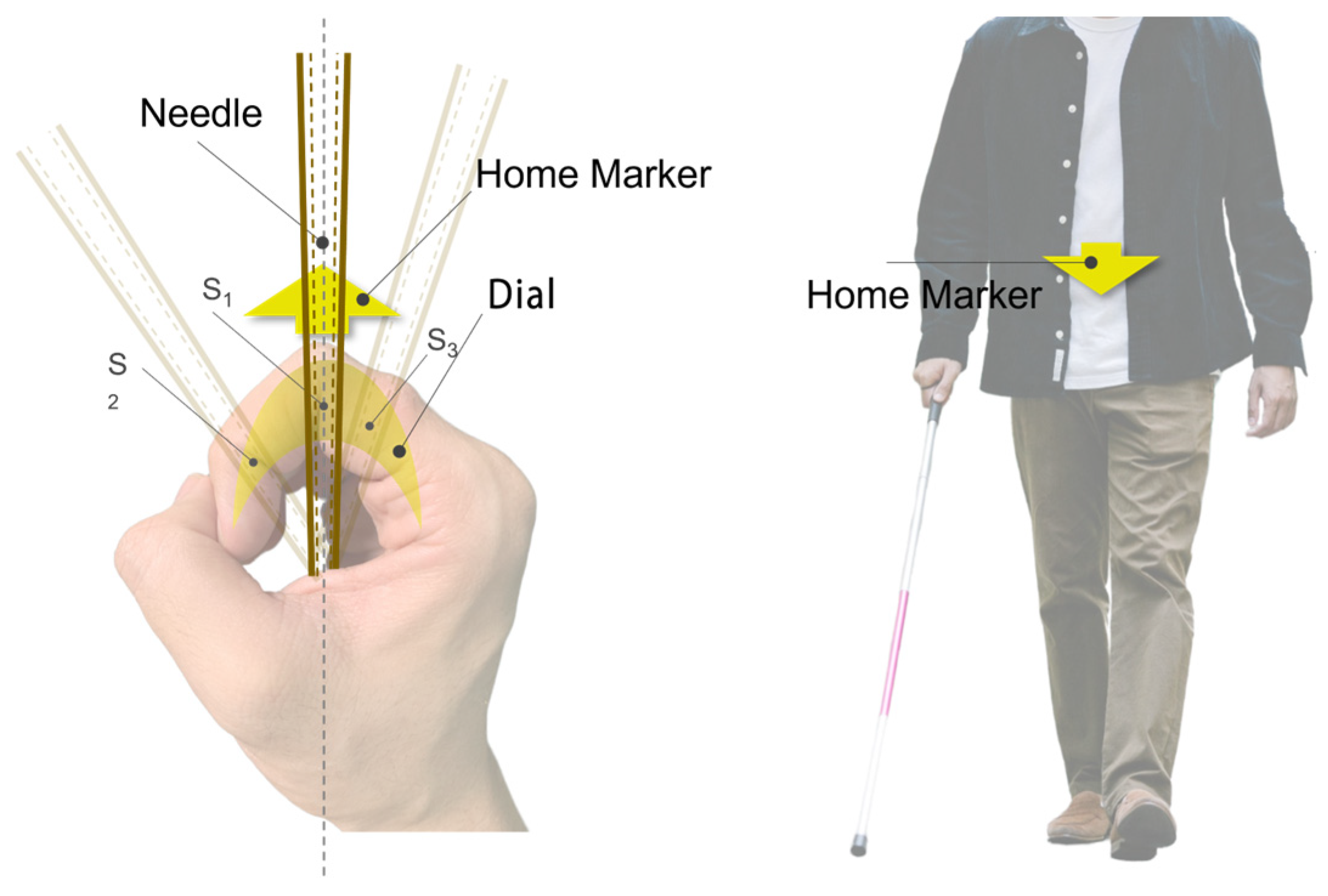
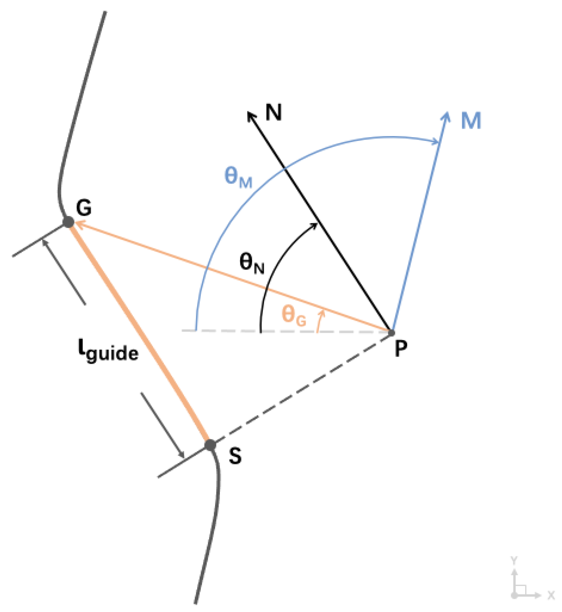
Specifically, as shown in
Figure 5, the flexible carbon fiber rod acts as a tactile rod, transmitting the traction force directional signals to the receptive area of the index finger. The user holds the assistive guiding handle of the perception module, orienting the second joint of the index finger directly forward, with the user’s fist serving as the central element of the spatial framework. Based on this, the user’s fist and the flexible carbon fiber rod create a directional feedback mechanism similar to that of a compass. Within this spatial framework, the direction indicated by the second joint of the index finger is referred to as the “Home Marker”, functioning similarly to the direction-of-travel arrow of a compass. The user needs to align their body’s forward direction with this marker.
Utilizing proprioception feedback for this compass-style interaction method is more consistent with the user’s inherent cognitive processing mechanisms, simplifying navigation tasks and allowing the user to navigate without focusing on the precise angular deflection of the tactile needle. Instead, the user only needs to subjectively judge the position of the contact point between the tactile rod and the index finger relative to the Home Marker, ensuring the rod remains aligned with the Home Marker during rotation. As illustrated in
Figure 6, in the initial state, the tactile needle’s indicated direction and the Home Marker are aligned with the user’s forward direction. When the Aerial Guide Dog transmits angular information, the tactile needle deviates from the Home Marker, rotating towards the target direction. At this point, the user’s index finger feels the tactile angular offset so that the user can rotate their wrist to realign the Home Marker with the new target direction and adjust the body orientation using the auxiliary module until the user’s forward direction aligns with the Home Marker, achieving the alignment of the forward direction and the target direction. This navigation method is simple and intuitive, requiring little cognitive thinking. Moreover, the device’s continuous kinesthetic feedback ensures that the user dynamically tracks the position of the contact point between the feedback signal and the user’s index finger throughout the process.
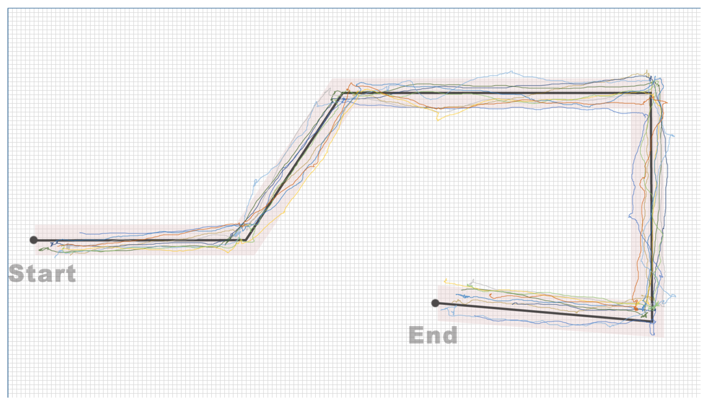
Additionally, considering the hardware limitations of the MG90S servo motor, the range of motion for the tactile needle is restricted to ±90° (a 180° area directly in front of the user). However, for practical use, guidance assistance devices need to provide feedback across a 360° range. To meet this requirement, when users perform rotation tasks beyond the ±90° range, the assistive guidance handle will first send a special directional signal to the user: the tactile needle will rotate to the target direction’s 90° position and immediately reverse back to the initial position. This special signal alerts the user to execute a 90° rotation. Therefore, when users need to rotate beyond the restricted angle, the assistive guidance handle will initially convey a special signal to prompt a 90° rotation. If the angle for the subsequent rotation lies within the motor’s operational range, a regular directional signal is then issued, guiding the user to follow the direction indicated by the tactile needle.
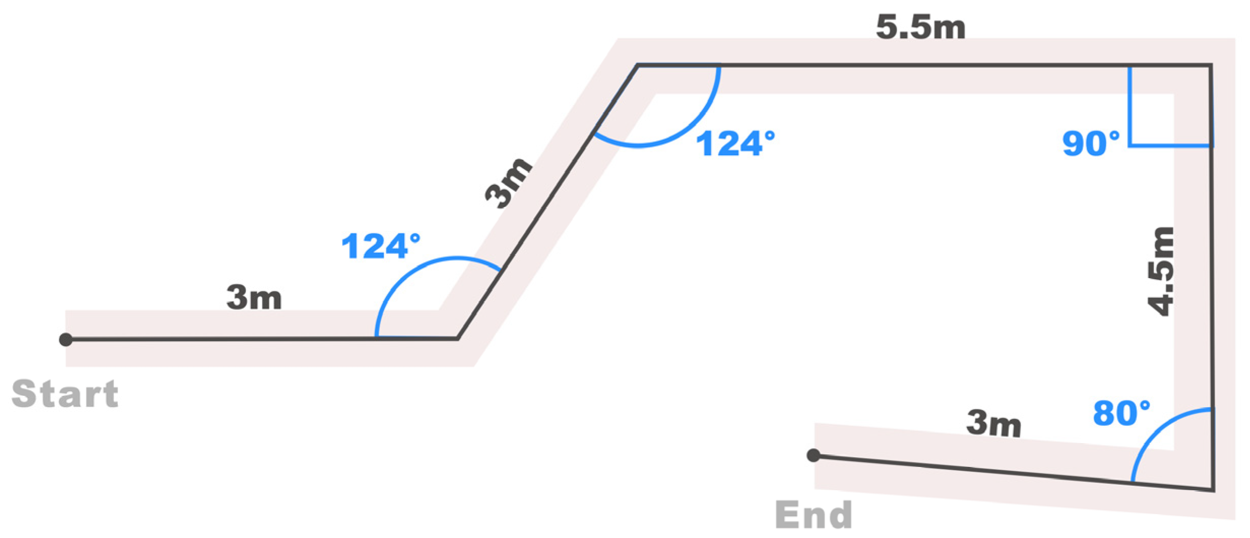
This improvement ensures comprehensive coverage of the feedback range, matching the device’s capabilities with comprehensive indoor navigation support requirements. Subsequent experimental analyses will evaluate two types of rotation situations separately: a special direction signal (SDS) situation, involving special directional signals for user rotations exceeding ±90°, and a non-special direction signal (non-SDS) situation, involving user rotations within the ±90° range. A subsequent experiment distinguishes these two situations to show how human rotating behaviors affect the angles of deviation.


