Abstract
The design of a mixed-mode proportional-integral-derivative (PID) controller circuit using current-feedback operational amplifiers (CFOAs) as active components is proposed. With the same circuit topology, the proposed configuration of three CFOAs, four resistors, and two capacitors is capable of performing the PID controller in each of the following four modes: voltage mode, trans-admittance mode, current mode, and trans-impedance mode. Numerous mathematical analyses are conducted to determine the controller’s performance under both ideal and non-ideal conditions. Additionally, the mixed-mode second-order lowpass filter is suggested and also used to examine the workability of the proposed mixed-mode PID controller in a feedback control structure. The proposed PID controller is implemented with the commercially available IC-type CFOA AD844, and the simulation results are presented to illustrate the functionality of the controller and its closed-loop control system. According to the findings, the total power consumption of the proposed PID controller is 0.348 W, with symmetrical supply voltages of ±9 V. It also has a temperature variation of less than 0.2% over the AD844’s usable range. Monte Carlo statistical analysis results revealed that the gain responses of the controller exhibited a deviation of no more than 7.72% from the theoretical value. The controlled filter in a closed-loop control system has a 43% faster rise time and peak time than the uncontrolled filter in all four modes of operation. It also has a steady-state error less than 0.2 mV for voltage responses and 0.72 µA for current responses.
1. Introduction
Proportional-integral-derivative (PID) controllers are the most significant control components used in numerous industrial processes [1]. It is estimated that over 90% of all dynamical control systems utilize a PID controller [2]. With its three-term functionality involving proportional, integral, and derivative actions, the PID controller handles the treatment of transient and steady-state responses and adjusts the level of system stability, which are effective solutions for a wide range of real-world control problems [3]. It also offers simplicity, robustness, wide applicability, and simple parameter tuning. As a result, the prevalence of PID control has greatly increased.
A literature review reveals that the PID controller implementation includes a wide variety of designs based on the use of different active elements [4,5,6,7,8,9,10,11,12,13,14,15,16,17,18,19]. In [4], voltage-feedback operational amplifiers (OAs) are extensively used to implement conventional voltage-mode (VM) PID controllers. The realized controller, however, requires a significant number of active and passive components. The constant gain bandwidth product and low slew rate of the OA also limit its response time. To overcome these limitations, some current-mode (CM) active components, such as the operational transconductance amplifier (OTA), current differencing buffered amplifier (CDBA), operational transresistance amplifier (OTRA), second-generation current conveyor (CCII), voltage differencing current conveyor (VDCC), and current-feedback operational amplifier (CFOA), are suggested for PID controller implementations. The OTA-based PID controller in [5] uses two grounded capacitors and eight OTAs. It supplies the output voltage signal at the high-impedance terminal, which is incompatible with cascading in VM. The PID controller designed with CDBAs requires four active and ten passive components and lacks high-input impedance [6]. In [7], the VM PID controller circuit is constructed with two OTRAs, four floating resistors, and three floating capacitors, but it does not have both high input and low output impedances. Based on CCIIs, the PID controller circuits are proposed in [8,9,10]. The works of [8,9] present two distinct configurations for VM and CM operations, while [10] only discusses CM operation. However, none of the CCII-based VM PID designs have low output impedance, and neither of the CM PID designs have low input impedance. As described in [11], a single VDCC-based VM PID controller circuit with a single input and two output terminals is realized with four resistors and two capacitors. It can simultaneously implement non-inverting and inverting control signals. However, the configuration does not fully utilize the differential input property of the VDCC because one of the differential inputs is not employed. This could be the result of input noise injection. Also, a recent VM PID controller using a single active component was reported in [12], but its limitations are the same as those in [11]. Three DDCCs and five passive elements are used in the construction of VM PID controllers [13]. At the inputs of all DDCCs, the high-input impedance and capability of arithmetic operations are not fully utilized. Some earlier works do not exhibit high-input and low-output impedances for VM [14,15] or low-input and high-output impedances for CM [16]. In addition, all of the proposed PID controllers in [4,5,6,7,8,9,10,11,12,13,14,15,16] are capable of operating in either VM or CM. In real-world process control applications, mixed-signal processing PID controllers are required to interact between CM and VM circuits. To satisfy this requirement, the trans-admittance-mode (TAM) and trans-impedance-mode (TIM) PID controller circuits are also used to interface between CM and VM units without any distortion. Only one of those controllers suggests a transconductor-capacitor-based mixed-mode PID design [17]. The active blocks used in the design are not commercially available. Note that implementing the controller with commercially available integrated circuit (IC) elements is advantageous from both a practical and a simplicity aspect. Consequently, the PID controller based on a single commercially available IC CFOA, two resistors, and two grounded capacitors was described in [18]. The design focuses solely on VM operation. In a recent work [19], two CM PID controllers were introduced, each comprising two CFOAs and four passive components. These controllers can be modified to work as mixed-mode PID controllers, capable of operating in all four possible modes. However, the modified controllers lack a high-impedance input feature, causing loading effects with the prior stage for the VM and TAM controllers. Therefore, an additional buffer circuit may be required for VM and TAM operations.
This work describes a mixed-mode PID controller circuit that utilizes three CFOAs as active components in addition to four resistors and two capacitors as passive components. The proposed controller has the capability of performing mixed-mode PID control responses, including VM, CM, TAM, and TIM, within a single topology. Table 1 provides a detailed comparison between the proposed circuit and earlier PID controllers [4,5,6,7,8,9,10,11,12,13,14,15,16,17,18,19]. Therefore, the major contributions of this work are as follows:

Table 1.
Comparison features of the proposed controller circuit with the earlier PID controllers [4,5,6,7,8,9,10,11,12,13,14,15,16,17,18,19].
- (1)
- We introduce the realization of a PID controller that can operate in all four possible modes without modifying its circuit configuration. The proposed controller provides high-input and low-output impedance properties for the voltage signal as well as low-input and high-output impedance properties for the current signal, allowing direct cascading with any VM or CM plant. By using the TAM and TIM operations, one can establish a connection between a voltage signal and any CM plant, and vice versa. For its implementation, all grounded capacitors are required, and there are no element-matching criteria or cancellation constraints.
- (2)
- The design utilizes a readily available IC-type CFOA AD844 as an active component, which is crucial for ensuring simplicity and practicality when applying the proposed controller. Since the PID controller always uses low frequencies, the use of the model parameters of the commercial CFOA makes the simulation result at lower frequencies match the theoretical results with low tolerances. This is due to the fact that parasitic resistance and capacitance have less of an impact than the CFOA that uses MOS-based parameters [19].
- (3)
- Furthermore, a mixed-mode second-order low-pass filter with a grounded capacitor is suggested, which can be used in all modes of operation, in order to assess the effectiveness of the proposed mixed-mode PID controller.
2. Proposed Mixed-Mode PID Controller Configuration
The CFOA is a four-terminal active device, represented symbolically in Figure 1. Its ideal characteristic is defined by iy = 0, vx = vy, iz = ix, and vw = vz. In addition, the characteristics of the CFOA with non-ideal transfer gains can be defined by the following terminal relations:
where β = (1 − εβ), α = (1 − εα), and γ = (1 − εγ). Further, εβ (|εβ| << 1) is the input-voltage tracking error, εα (|εα| << 1) is the input-current tracking error, and εγ (|εγ| << 1) is the output-voltage tracking error. All of the parameters β, α, and γ should ideally equal one.
iy = 0, vx = βvy, iz = αix, and vw = γvz,
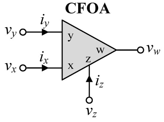
Figure 1.
CFOA circuit representation.
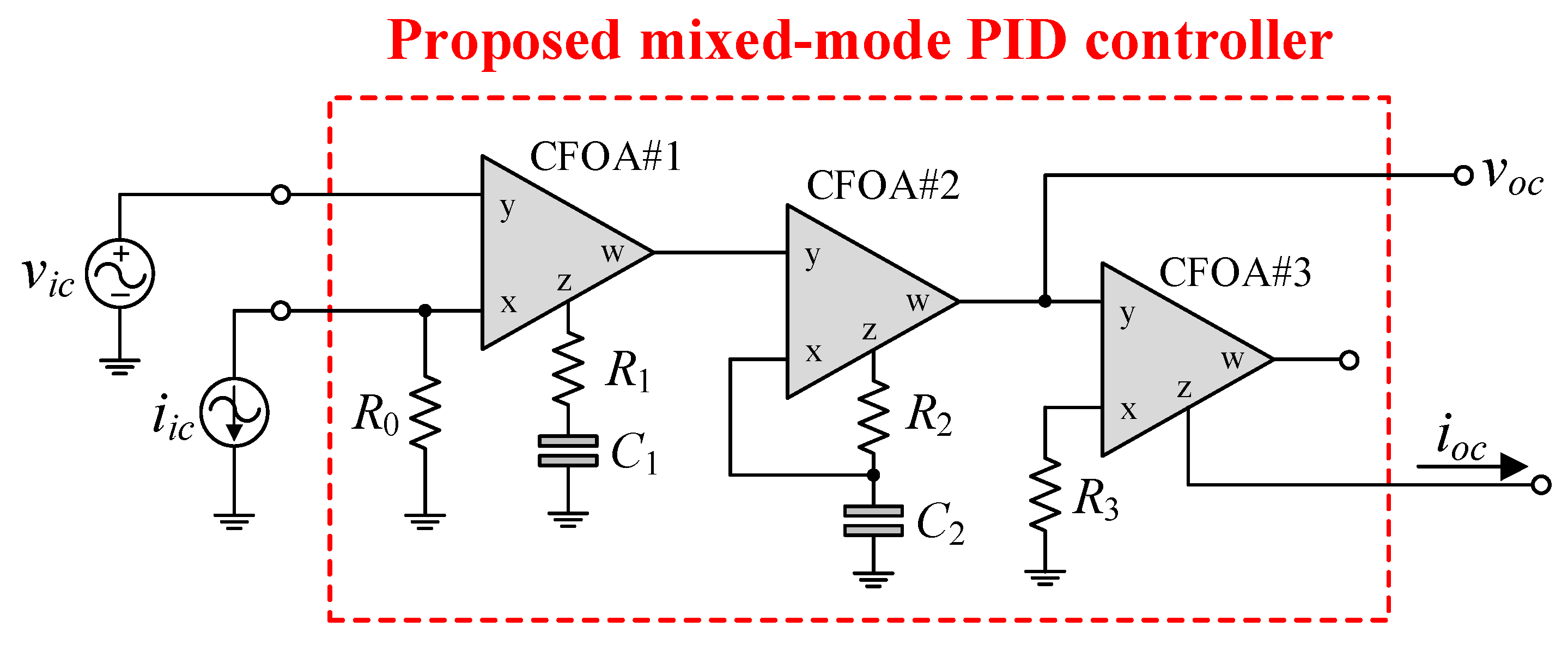
Figure 2 depicts the configuration of the proposed mixed-mode PID controller, which consists of two input terminals (vic and iic) and two output terminals (voc and ioc). For the VM signal, the circuit provides high-input and low-output impedance, while for the CM signal, it provides low-input and high-output impedance. By appropriately employing the relevant input signals via vic and iic, the proposed PID controller can realize all four possible modes of operation, VM, TIM, CM, and TAM, in a single topology. Consequently, it is a mixed-mode PID controller.
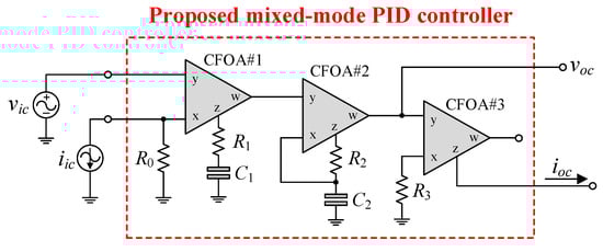
Figure 2.
Proposed mixed-mode PID controller configuration using CFOAs.
The general transfer function of the PID controller can be expressed as:
where the parameters KP, KI, and KD are the proportional gain, integral gain, and derivative gain of the controller, respectively.
2.1. VM and TAM Operations
Comparing Equation (3) to Equation (2), the important gain coefficients of the proposed VM PID controller are obtained as follows:
and
In Equation (4), the parameters KPV, KIV, and KDV are the gains KP, KI, and KD for VM, respectively.
Similarly, the transfer function of the proposed TAM PID controller is also obtained as:
where
and
Since the primary objective of this communication is to design an analog PID controller with all four modes of operation in a single configuration, orthogonal adjustment of the control gain parameters KPV(Y), KIV(Y), and KDV(Y) derived from Equations (4) and (6) is not anticipated. However, independent tuning of KIV(Y) and KDV(Y) is possible via R0 and C2, respectively, by adjusting R0, R1, C1, and C2 simultaneously in order that R1/R0 and C2/C1 remain constant.
2.2. CM and TIM Operations
Furthermore, by applying iin while connecting vic to ground (vic = 0), the proposed circuit in Figure 2 can be used for CM PID control. As a consequence, the realized transfer function of the CM PID controller is
For R0 = R3, the gain parameters KPI, KII, and KDI of the CM PID controller in Equation (7) are the exact same as KPV, KIV, and KDV in Equation (4).
It is also observed that the transfer function of the proposed TIM PID controller is found as:
where
and
According to Equations (4), (6) and (9), it can be observed that the relative element sensitivities of the control coefficients are low, in that their values are all less than unity, as given below:
and
3. Non-Ideality Effects of CFOA Parasitic Gains
In practice, the CFOA may take into account the non-ideal transfer gains β, α, and γ. According to Equation (1), when β ≠ α ≠ γ ≠ 1, the following are the practical gain parameters of the proposed PID controller in Figure 2.
For VM operation, the control parameters KPV, KIV, and KDV are nonideally obtained as:
and
where the multiplication coefficients βi, αi, and γi (i = 1, 2, 3) denote the non-ideal gains β, α, and γ of the i-th CFOA, respectively.
For TAM operation, the non-ideal control parameters KPY, KIY, and KDY can be expressed as:
and
For CM and TIM operations, the non-ideal control parameters can be determined, respectively, as follows:
and
According to Equations (15)–(18), the gain parameters of the proposed PID controller differ slightly owing to the non-ideal transfer gains βi, αi, and γi. Inspecting these equations implies that all PID control coefficient sensitivities with respect to non-ideal transfer gains of the CFOA are not greater than unity in absolute value.
4. Non-Ideality Effects of CFOA Parasitic Impedances
Figure 3 shows the non-ideal behavior model of the practical CFOA, including the typical parasitic impedances. In accordance with this model, Rx and Rw are the low-level parasitic resistances, Rz is the high-level parasitic resistance, and Cz is the parasitic capacitance, associated with the corresponding terminals. For example, the parasitic element values for the commercially available integrated circuit (IC) AD844 CFOA are as follows: Rx = 50 Ω, Rw = 15 Ω, Rz = 3 MΩ, and Cz = 4.5 pF [20].
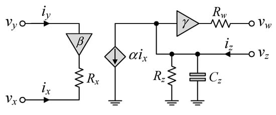
Figure 3.
Non-ideal behavior model of the CFOA.
Considering the dominant parasitic effects of the CFOA on the performance of the proposed mixed-mode PID controller in Figure 2, the following additional assumptions can be defined under the conditions that β ≅ α ≅ γ ≅ 1:
and
In practice, the impacts of the parasitic resistances Rx1 and Rx3 are negligible due to the fact that R0 >> Rx1 and R3 >> Rx3. The expression in Equation (19) can be rewritten as:
When the parasitic capacitance Cz1 is minimal, the operating frequency is limited to the following range:
Additionally, from Equation (21), if Rz1 is negligible, the range of applicable frequencies is as follows:
For instance, if the commercially available IC AD844 CFOA is employed with R1 = 5 kΩ, and C1 = 1 nF, the useful operating frequencies found from Equations (22) and (23) are around f1 ≅ 53 Hz, and f2 ≅ 7.07 MHz.
Assuming that R2 >> Rx2, Equation (20) can be rearranged as:
In the same manner, the practical frequency range in this case is limited to
By utilizing R2 = 5 kΩ, Rz2 = 3 MΩ, and Cz2 = 4.5 pF, it is possible to determine the frequency location of f3 ≅ 7.07 MHz.
By combining Equations (22), (23) and (25), the proposed mixed-mode PID controller shown in Figure 2 can be effectively utilized over the following frequency range:
5. Functional Simulation and Discussion
In order to validate the theoretical analysis presented in the previous section, the proposed mixed-mode PID controller circuit depicted in Figure 2 was investigated using the PSPICE program with model parameters of the commercial CFOA IC-type AD844, available from Analog Devices, Wilmington, MA, USA [20]. All the AD844 ICs were biased with symmetrical power supplies of ±9 V. The passive components for the controller were set as: R0 = 1 kΩ, R1 = R2 = R3 = 5 kΩ, and C1 = C2 = 1 nF. For the specified component values, the controller parameters were calculated as follows:
- KPV = 7.5, KIV = 1 Ms−1, and KDV = 12.5 μs for VM;
- KPY = 1.5 m, KIY = 200 s−1, and KDY = 2.5 ns for TAM;
- KPI = 1.5, KII = 0.2 Ms−1, and KDI = 2.5 μs for CM;
- KPZ = 7.5 k, KIZ = 1 Gs−1, and KDZ = 12.5 ms for TIM.
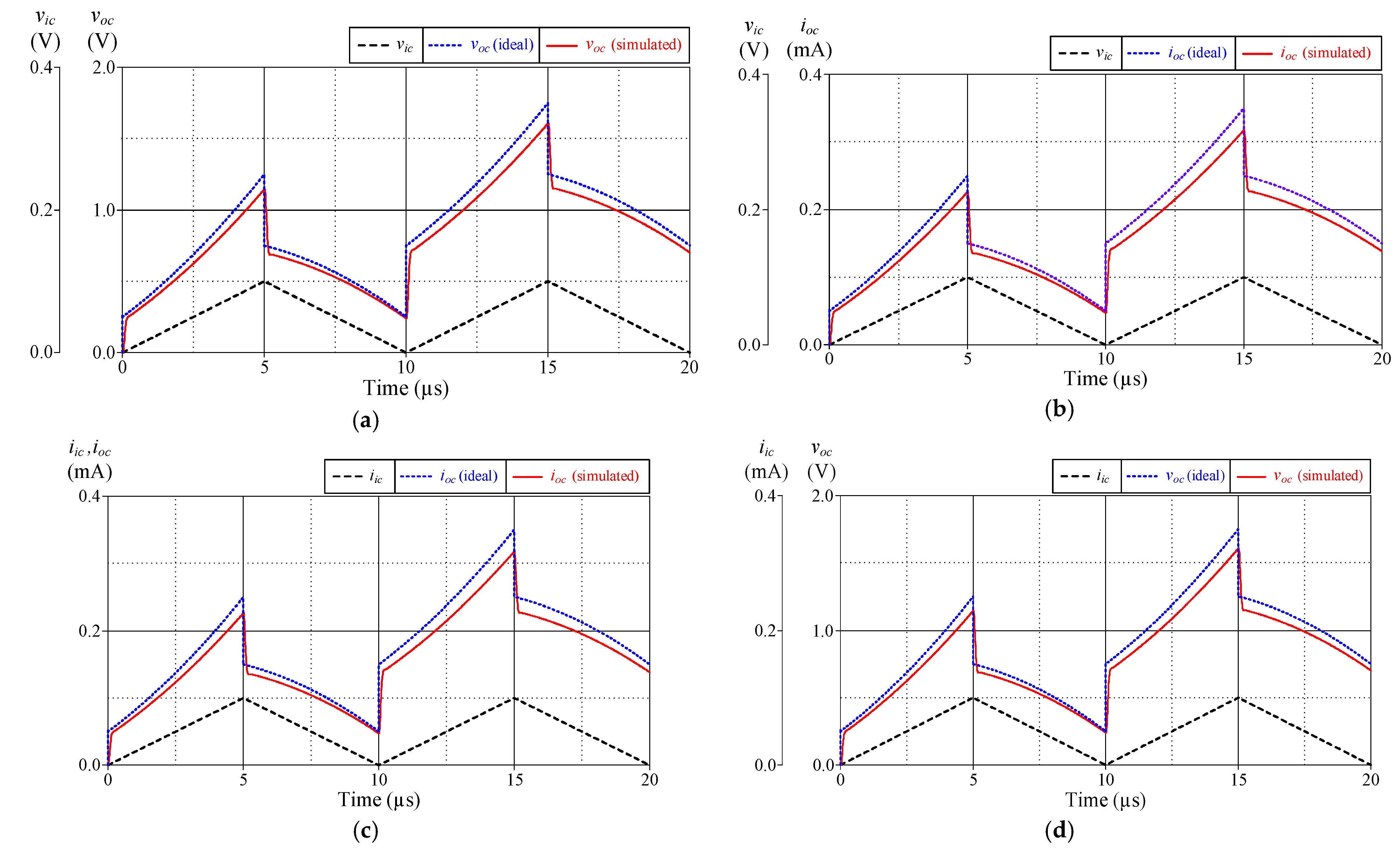
Figure 4 illustrates the time-domain simulation responses of the VM, TAM, CM, and TIM PID controllers in comparison to the ideal responses. As shown in Figure 4, the controller was applied with a 100-kHz triangular input signal with 100 mV peak amplitude for VM and TAM and 100 μA peak amplitude for CM and TIM.
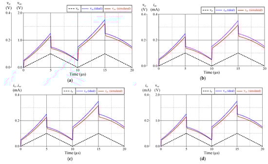
Figure 4.
Ideal and simulated time-domain responses of the proposed controller in Figure 2: (a) VM; (b) TAM; (c) CM; (d) TIM.
Figure 5 additionally illustrates the ideal and simulated frequency-domain characteristics of the proposed mixed-mode PID controller with the exact same components. It is evident from these responses that the gain-frequency limitation of the controller occurs predominantly at more than 5 MHz, with an error of no more than 9.56%. This phenomenon can be attributed to the dominant pole frequencies of parasitic impedances, as expected in the previous section. According to the simulation results, the total power consumption of the controller, comprising static and dynamic power losses, is estimated to be 0.348 W.
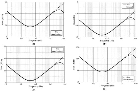
Figure 5.
Ideal and simulated frequency-domain responses of the proposed controller in Figure 2: (a) VM; (b) TAM; (c) CM; (d) TIM.
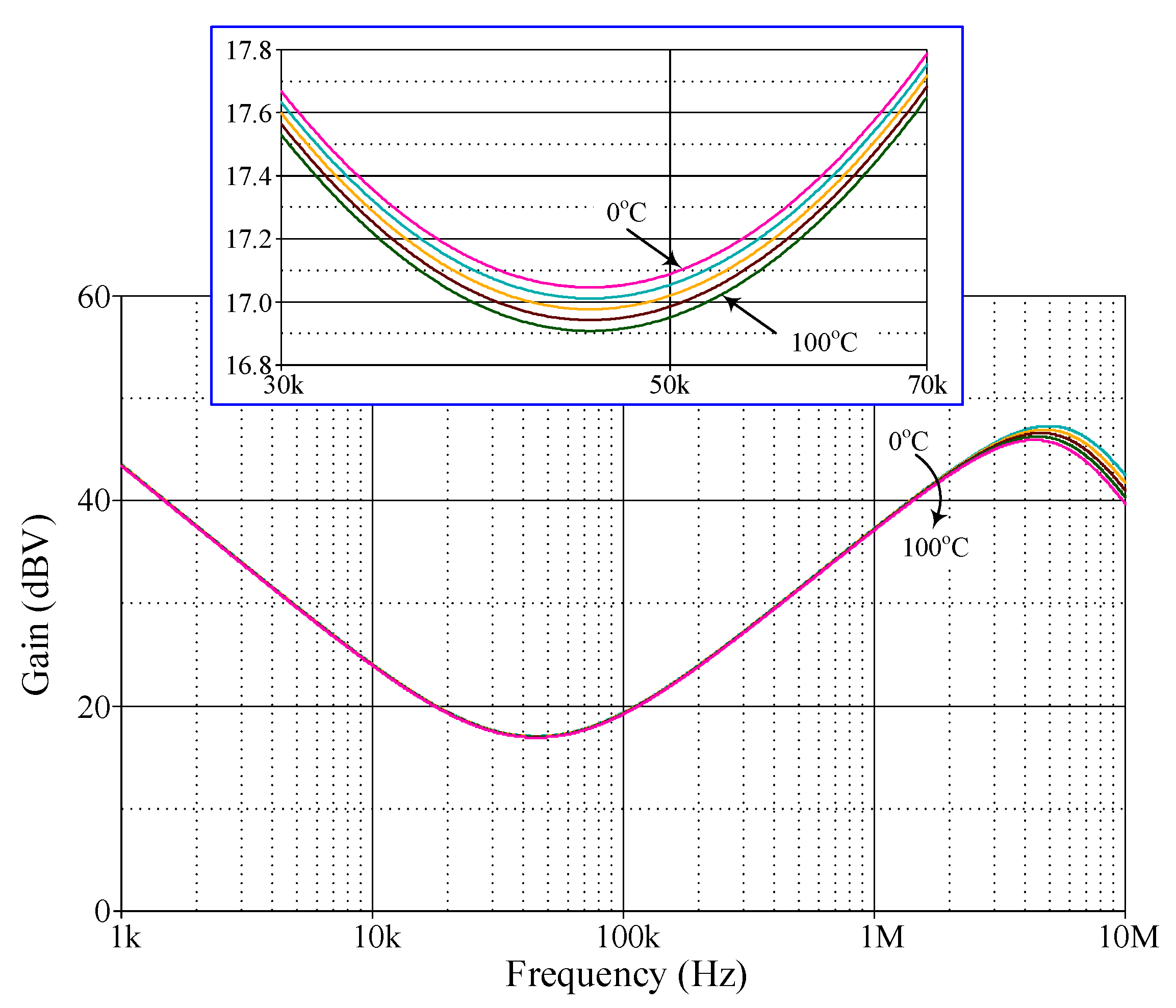
A further analysis was conducted on the gain response variation in the proposed VM PID controller with respect to ambient temperature. The temperature analysis was performed at the following temperatures: T = 0 °C, 25 °C, 50 °C, 75 °C, and 100 °C. Figure 6 illustrates the simulation results of the analysis of ambient temperature, while Table 2 presents the controller gain values for various temperatures. Based on the data given in Table 2, the controller gain change with respect to temperature variation (ΔdBV/ΔT) is determined to be 0.137%, 0.138%, and 0.179% at f = 10 kHz, 100 kHz, and 1 MHz, respectively.
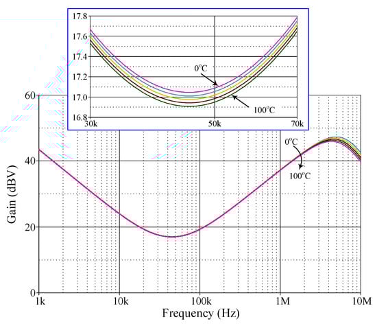
Figure 6.
Simulated frequency responses of the proposed VM PID controller with ambient temperature variation.
Table 2.
Temperature dependence of the gain value for the proposed VM PID controller.
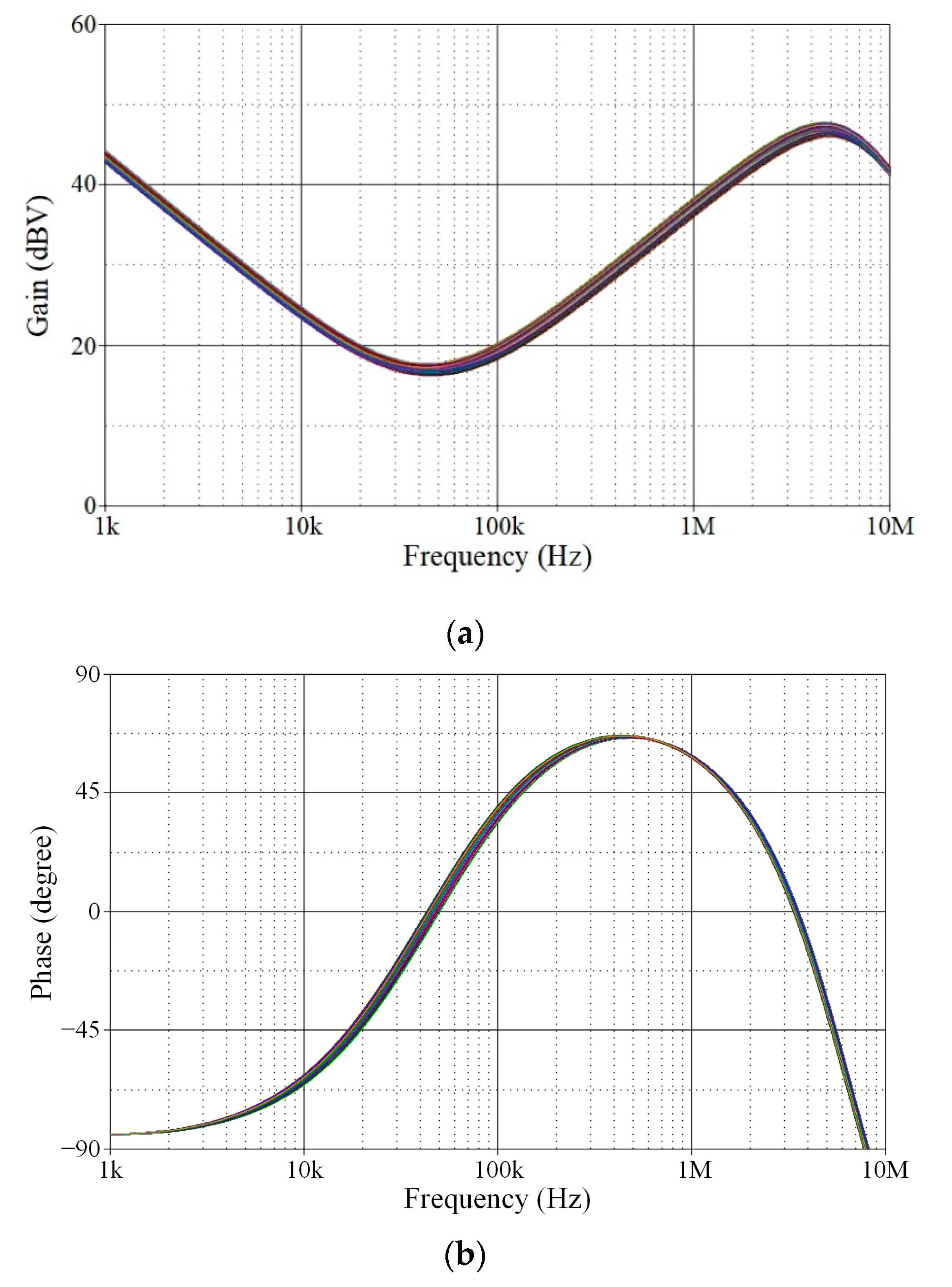
Additionally, Monte Carlo statistical analysis has been performed to demonstrate the robustness of the proposed controller. The analysis was conducted using 200 simulation runs in which the resistor and capacitor values were subject to a 5% Gaussian deviation. The Monte Carlo analysis results are shown in Figure 7, in which the gain responses of the proposed controller deviated from the theoretical value by less than 7.72%. The results indicate that a change in the passive component has no significant effect on the phase or gain responses of the controller.
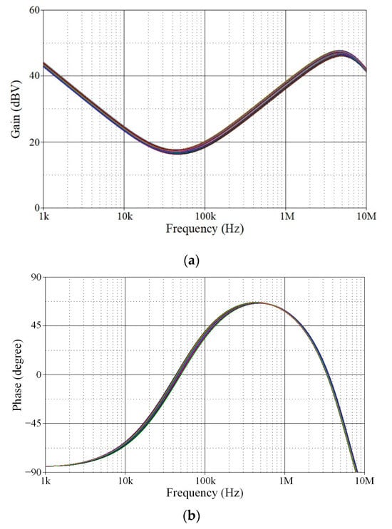
Figure 7.
Monte Carlo statistical analysis results of the proposed VM PID controller: (a) gain response; (b) phase response.
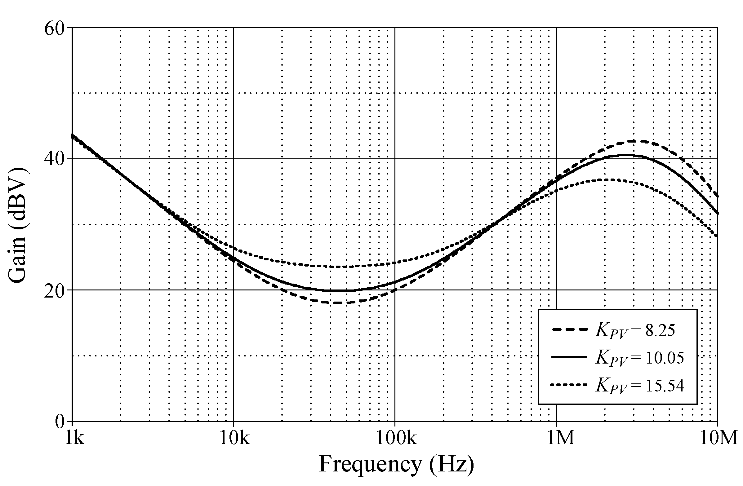
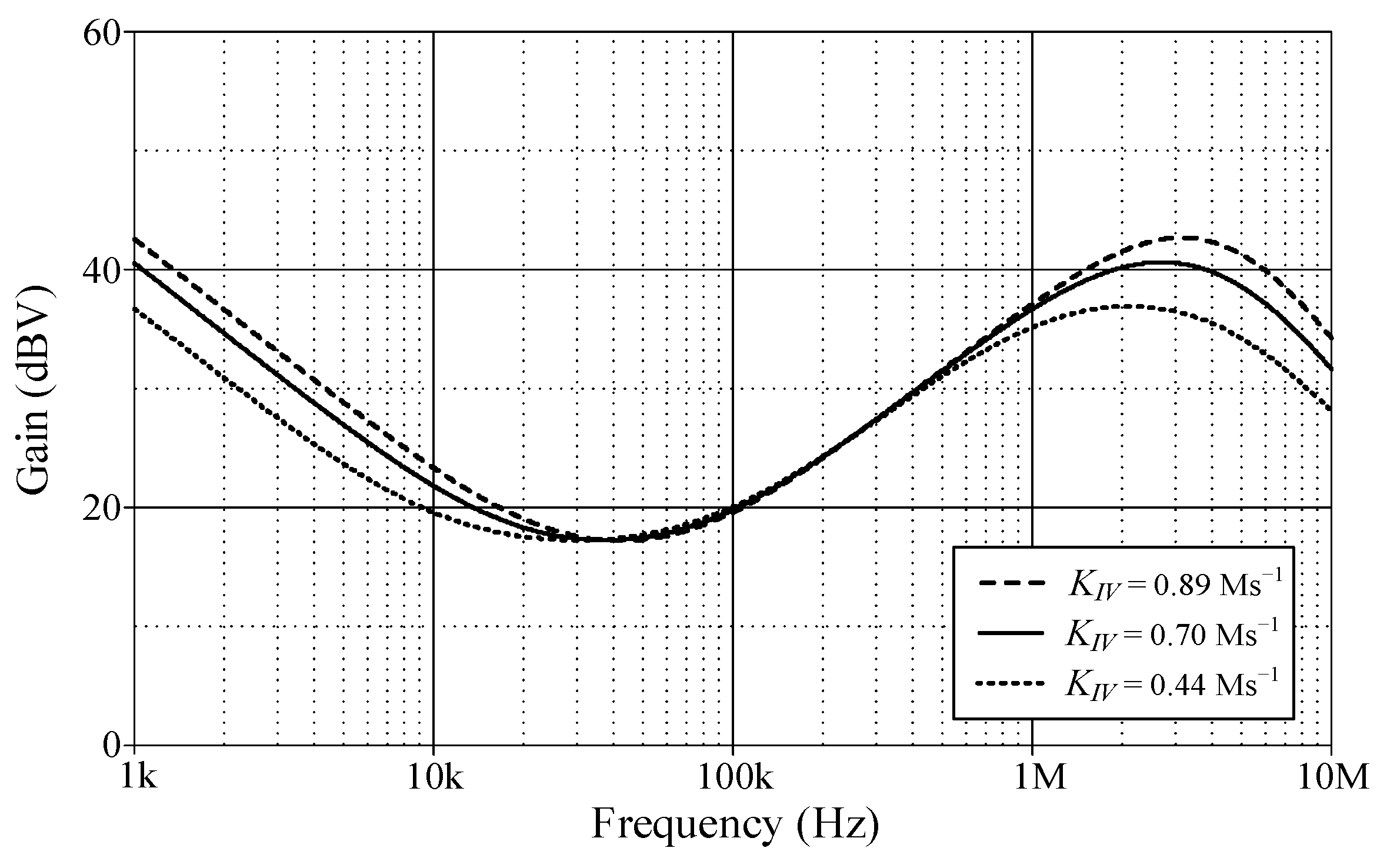
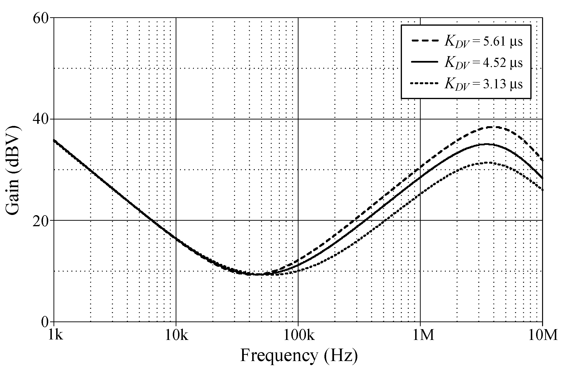
In order to evaluate the tuning performance, the simulations have been carried out by varying the coefficients KPV, KIV, and KDV of the VM controller. For our first tuning example, the values of various controller components for the variation in controller coefficient KPV, while holding KIV and KDV constants, are given in Table 3. As evident in Figure 8, the parameter KPV influences the entire operational range, as it appears from the gain response of the controller. The variations in the KIV and KDV values resulting from the use of different component values are also provided in Table 4 and Table 5. For the specified set parameters, the gain responses of the VM PID controller with tuning KIV and KDV are illustrated in Figure 9 and Figure 10, respectively.
Table 3.
Different component values for the variation in controller coefficient KPV.
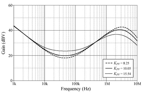
Figure 8.
Gain-frequency responses of the proposed VM PID controller when adjusting KPV while keeping KIV and KDV constant.
Table 4.
Different component values for the variation in controller coefficient KIV.
Table 5.
Different component values for the variation in controller coefficient KDV.

Figure 9.
Gain-frequency responses of the proposed VM PID controller when adjusting KIV while keeping KPV and KDV constant.
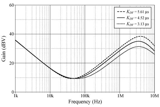
Figure 10.
Gain-frequency responses of the proposed VM PID controller when adjusting KDV while keeping KPV and KIV constant.
6. Performance Verification with Closed-Loop Control Implementation
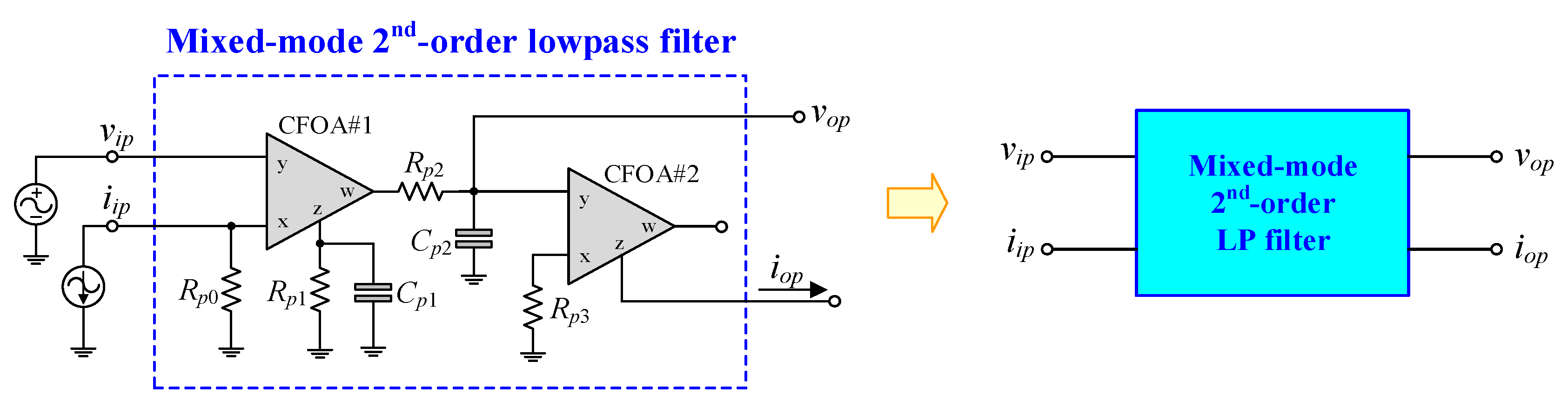
In order to assess the effectiveness of the proposed mixed-mode PID controller in Figure 2, the mixed-mode second-order lowpass (LP) filter depicted in Figure 11 is suggested as a plant for implementing a closed-loop control system. The suggested LP filter can be realized for all four-mode LP filters with the following transfer functions:
where
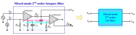
Figure 11.
Suggested mixed-mode low-pass filter.
From Equations (27)–(31), the natural angular frequency (ωn) and the quality factor (Q) for the filter are respectively obtained as:
and
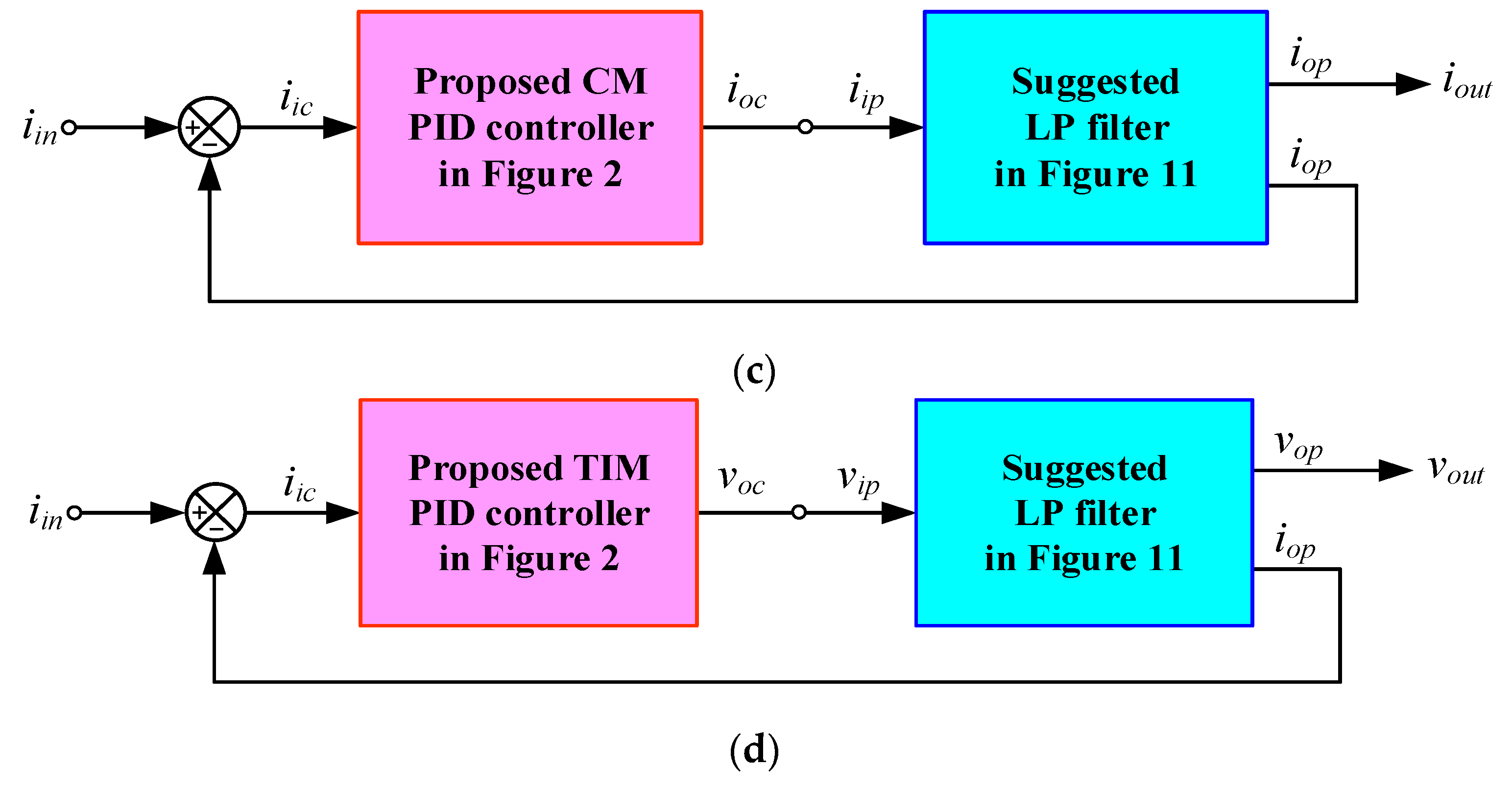
The implemented closed-loop systems, as depicted in Figure 12, utilize the mixed-mode PID controller proposed in Figure 2 and the filter plant suggested in Figure 11. The configurations depicted in Figure 12a–d were constructed for the performance assessment of VM, TAM, CM, and TIM controllers, respectively. The component values for the filters are as follows: Rp0 = Rp1 = Rp2 = Rp3 = 1 kΩ, and Cp1 = Cp2 = 1 nF; thus, fn = 159 kHz and Q = 0.5 are obtained. All implemented controllers utilized R1 = R3 = 5 kΩ and C1 = C2 = 200 pF.
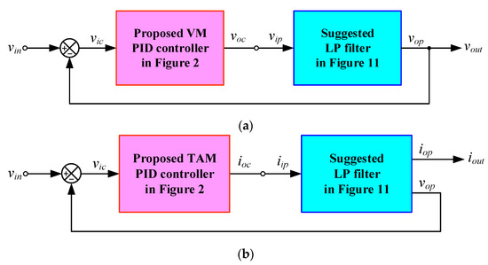
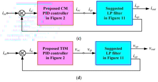
Figure 12.
Closed-loop control system implementation: (a) VM; (b) TAM; (c) CM; (d) TIM.
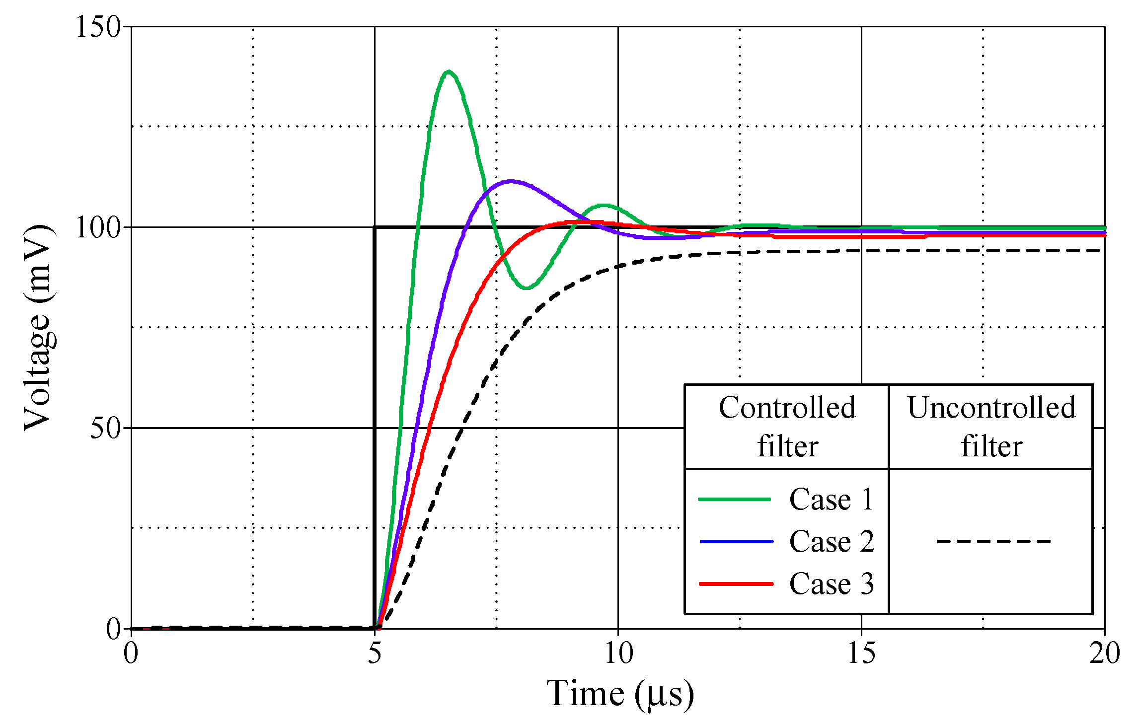
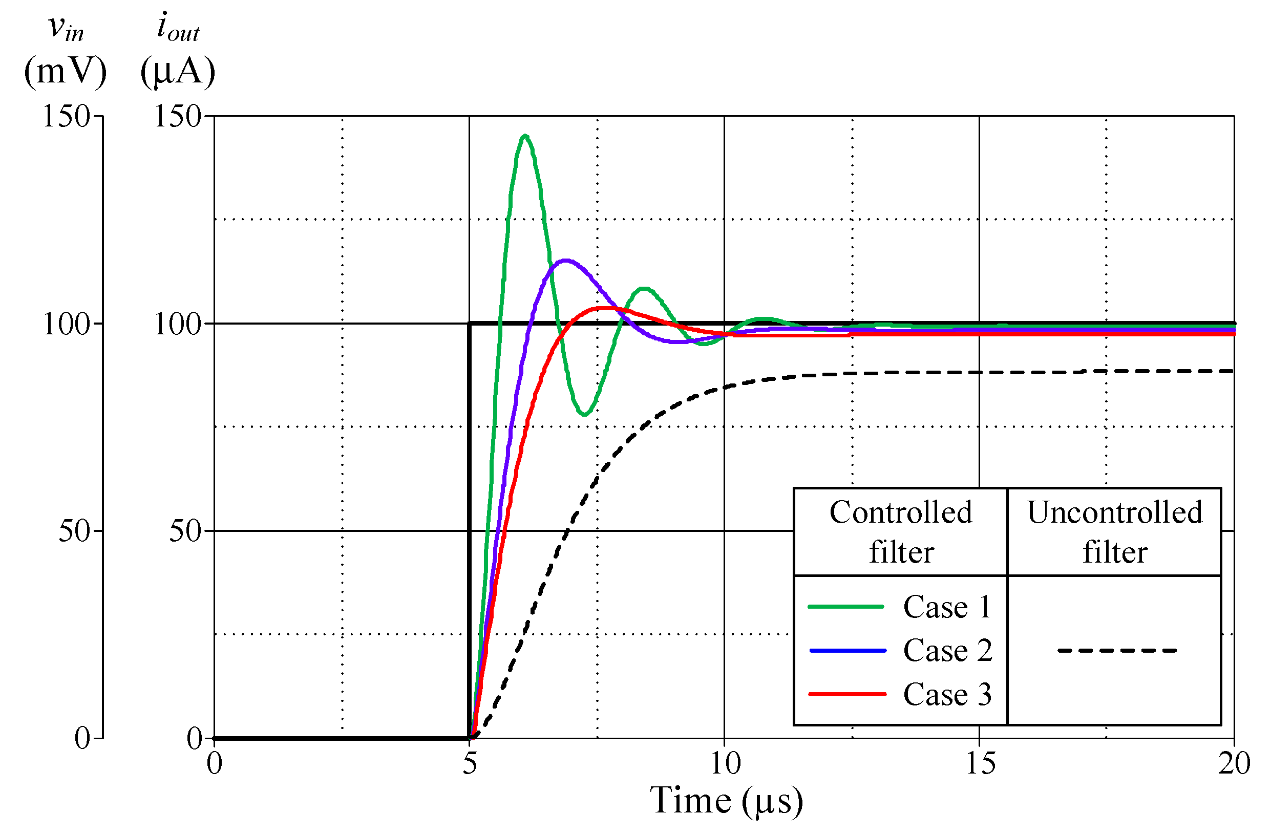
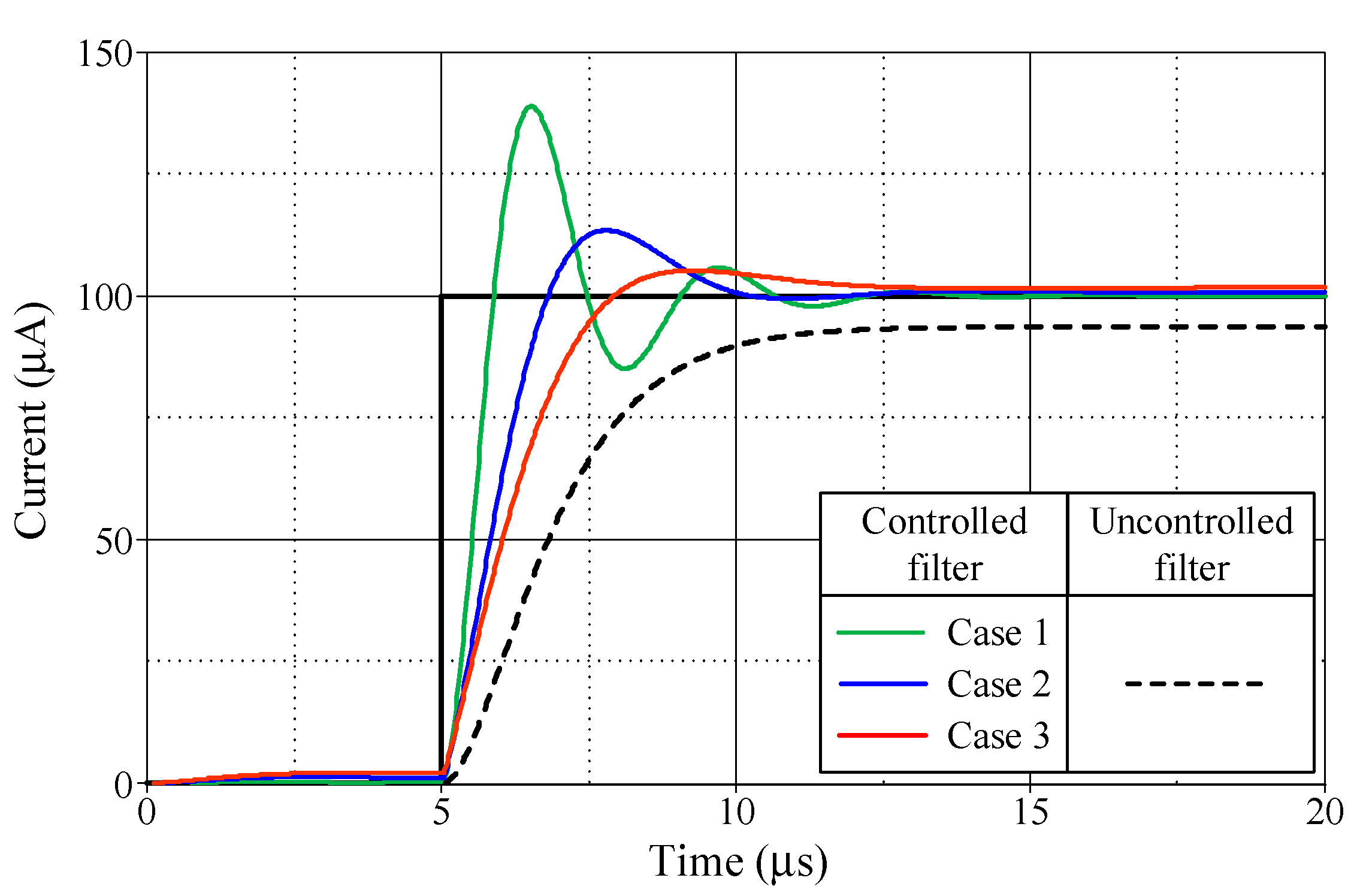
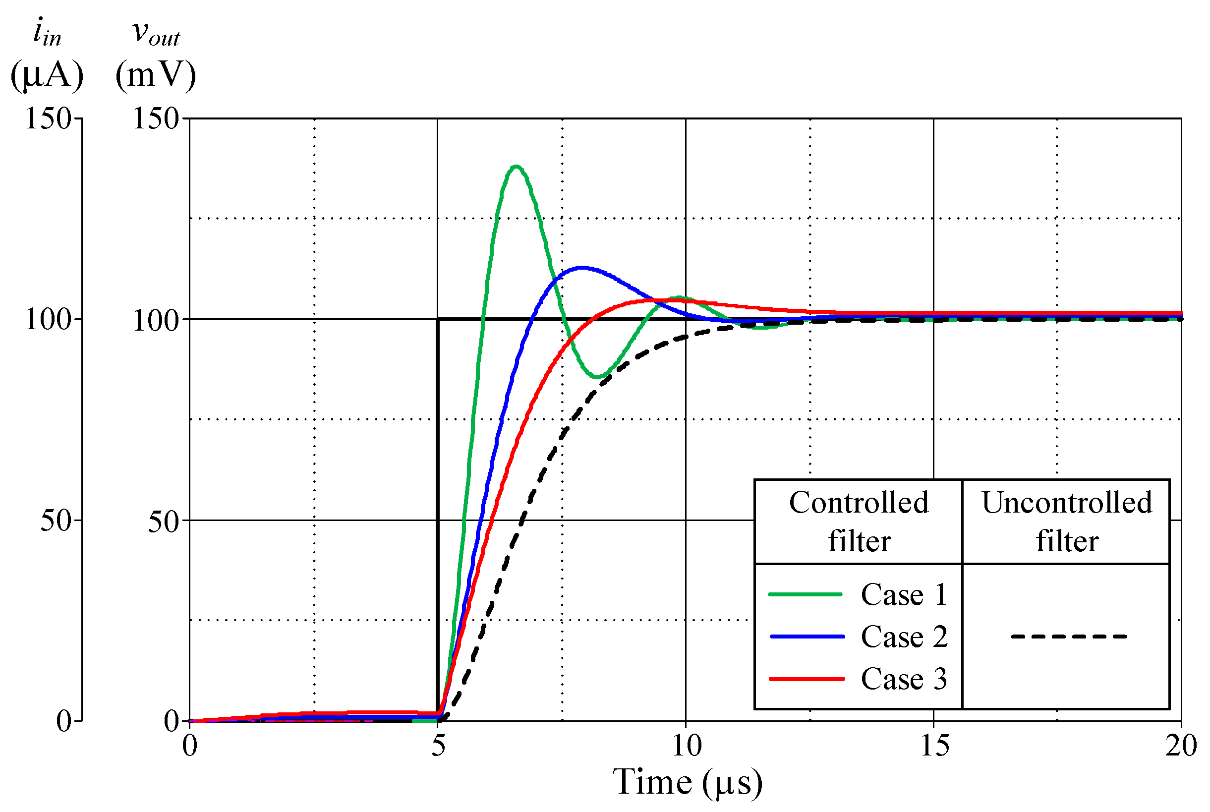
Figure 13, Figure 14, Figure 15 and Figure 16 illustrate the step responses of the uncontrolled filter and PID-controlled filter systems for Figure 12a–d, respectively. The controller parameters employed to evaluate the step response, along with the characteristics derived from the responses for each of the four modes, are also documented in Table 6, Table 7, Table 8 and Table 9. It is evident from the tables that the proposed PID controllers improved the time response of the closed-loop control filter systems, particularly for td, tr, tp, and ts. The times tr and tp of the controlled filter in a closed-loop control system were 43% faster than those of the uncontrolled filter in all four modes of operation. It also had a steady-state error of less than 0.2 mV for voltage responses and 0.72 µA for current responses. Additionally, the controlled filters entered the steady-state faster than the uncontrolled filters and tracked the step-input with a reduced steady-state error.
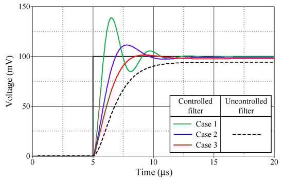
Figure 13.
Step-responses of the uncontrolled and controlled filters in Figure 12a.
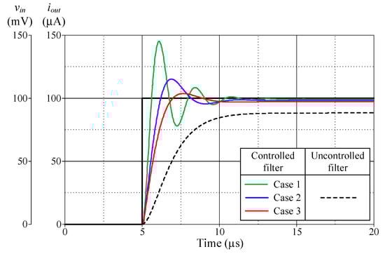
Figure 14.
Step-responses of the uncontrolled and controlled filters in Figure 12b.
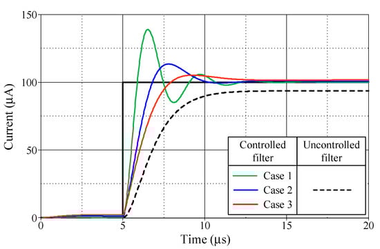
Figure 15.
Step-responses of the uncontrolled and controlled filters in Figure 12c.
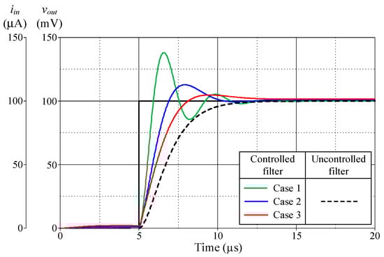
Figure 16.
Step-responses of the uncontrolled and controlled filters in Figure 12d.
Table 6.
Controller parameters and the resulting characteristics of the uncontrolled filter and controlled filter systems shown in Figure 12a.
Table 7.
Controller parameters and the resulting characteristics of the uncontrolled filter and controlled filter systems shown in Figure 12b.
Table 8.
Controller parameters and the resulting characteristics of the uncontrolled filter and controlled filter systems shown in Figure 12c.
Table 9.
Controller parameters and the resulting characteristics of the uncontrolled filter and controlled filter systems shown in Figure 12d.
7. Conclusions
This work presents a tunable mixed-mode PID controller implemented with commercially available integrated circuits (ICs) and current-feedback operational amplifiers (CFOAs). The presented PID controller circuit employs three CFOAs, four resistors, and two capacitors. All four operational-mode PID controllers, namely VM, TAM, CM, and TIM, can be performed with a single proposed circuit topology. The important parameters of the proposed PID controllers, namely, KP, KI, and KD, are modifiable as desired. Since the proposed controller is designed using only off-the-shelf ICs together with some passive components, it has advantages in terms of practicality and simplicity. Analyses of non-ideal transfer gain and parasitic effects on the controller performance have also been examined in detail. In addition, to evaluate the practical applicability of the proposed mixed-mode PID controller, the mixed-mode second-order lowpass filter is designed to be a testing plant for a mixed-mode closed-loop control system. A simulation study demonstrates the performance of the circuit.
Author Contributions
Conceptualization, N.R., J.S. and W.T.; methodology, N.R., J.S., T.P. and W.T.; software, N.R. and J.S.; validation, N.R., J.S., T.P. and W.T.; formal analysis, N.R., J.S. and W.T.; investigation, N.R., J.S., T.P. and W.T.; resources, N.R., J.S., T.P. and W.T.; data curation, N.R., J.S. and W.T.; writing—original draft preparation, N.R., J.S. and W.T.; writing—review and editing, T.P. and W.T.; visualization, N.R., J.S. and W.T.; supervision, T.P. and W.T.; project administration, T.P. and W.T. All authors have read and agreed to the published version of the manuscript.
Funding
This work was financially supported by King Mongkut’s Institute of Technology Ladkrabang [2567-02-01-067].
Institutional Review Board Statement
Not applicable.
Informed Consent Statement
Not applicable.
Data Availability Statement
Data are contained within the article.
Conflicts of Interest
The authors declare no conflicts of interest.
References
- Michael, A.J.; Mohammad, H.M. PID Control New Identification and Design Methods; Springer: Berlin/Heidelberg, Germany, 2005. [Google Scholar]
- Astrom, K.J.; Hagglund, T. The future of PID control. Control Eng. Pract. 2001, 9, 1163–1175. [Google Scholar] [CrossRef]
- Astrom, K.J.; Hagglund, T. PID Controllers: Theory, Design and Tuning, 2nd ed.; Instrument Society of America: Research Triangle Park, NC, USA, 1995. [Google Scholar]
- Franco, S. Design with Operational Amplifiers and Analog Integrated Circuits, 3rd ed.; McGraw-Hill: Boston, MA, USA, 2002. [Google Scholar]
- Erdal, C.; Toker, A.; Acar, C. OTA-based proportional-integral-derivative (PID) controller and calculating optimum parameter tolerances. Turk. J. Elec. Engin. 2001, 9, 189–198. [Google Scholar]
- Keskin, A.U. Design of PID controller circuit employing CDBAs. Int. J. Electr. Eng. Educ. 2006, 43, 48–56. [Google Scholar] [CrossRef]
- Pandey, R.; Pandey, N.; Chitranshi, S.; Paul, S.K. Operational transresistance amplifier based PID controller. Adv. Electr. Electron. Eng. 2015, 13, 171–181. [Google Scholar] [CrossRef]
- Yuce, E.; Tokat, S.; Minaei, S.; Cicekoglu, O. Low-component-count insensitive current-mode and voltage-mode PID, PI and PD controllers. Frequenz 2006, 60, 65–69. [Google Scholar] [CrossRef]
- Yuce, E.; Tokat, S.; Kizilkaya, A.; Cicekoglu, O. CCII-based PID controllers employing grounded passive components. AEU Int. J. Electron. Commun. 2006, 60, 399–403. [Google Scholar] [CrossRef]
- Yuce, E.; Minaei, S. New CCII-based versatile structure for realizing PID controllers and instrumentation amplifier. Microelectron. J. 2010, 41, 311–316. [Google Scholar] [CrossRef]
- Ozer, E.; Kacar, F. Design of voltage-mode PID controller using a single voltage differencing current conveyor (VDCC). Analog Integr. Circuits Signal Process. 2021, 109, 11–27. [Google Scholar] [CrossRef]
- Shrivastava, P.; Surendra, S.; Ranjan, R.K.; Shrivastav, A.; Priyadarshini, B. PI, PD and PID controllers using single DVCCTA. Iran. J. Sci. Technol. Trans. Electr. Eng. 2019, 43, 673–685. [Google Scholar] [CrossRef]
- Yuce, E.; Alpaslan, H. DDCC+ based voltage-mode PID controller employing only grounded passive components. Indian J. Eng. Mater. Sci. 2016, 23, 120–128. [Google Scholar]
- Tangsrirat, W. Voltage-mode analog PID controller using a single z-copy current follower transconductance amplifier (ZC-CFTA). Inf. MIDEM 2015, 45, 175–179. [Google Scholar]
- Mongkolwai, P.; Tangsrirat, W.; Suesut, T. Novel voltage-Mode PID controller using a single CCTA and all grounded passive components. Inf. MIDEM 2022, 52, 169–179. [Google Scholar] [CrossRef]
- Taskıran, Z.G.Ç.; Sedef, H.; Anday, F. A new PID controller circuit design using CFOAs. Circuits Syst. Signal Process. 2021, 40, 1166–1182. [Google Scholar] [CrossRef]
- Silaruam, V.; Lorsawatsiri, A.; Wongtaychatham, C. Novel resistorless mixed-mode PID controller with improved low-frequency performance. Radioengineering 2013, 22, 932–940. [Google Scholar]
- Ayten, U.E.; Yuce, E.; Minaei, S. A voltage-mode PID controller using a single CFOA and only grounded capacitors. Microelectron. J. 2018, 81, 84–93. [Google Scholar] [CrossRef]
- Yurdem, B.; Sagbas, M.; Ayten, U.E. Current-mode PID controllers employing commercially available active components. AEU Int. J. Electron. Commun. 2024, 175, 155104. [Google Scholar] [CrossRef]
- Analog Devices, AD844: 60 MHz, 2000 V/µs, Monolithic op amp with Quad Low Noise. Available online: https://www.analog.com/media/en/technical-documentation/data-sheets/AD844.pdf (accessed on 29 June 2022).


Disclaimer/Publisher’s Note: The statements, opinions and data contained in all publications are solely those of the individual author(s) and contributor(s) and not of MDPI and/or the editor(s). MDPI and/or the editor(s) disclaim responsibility for any injury to people or property resulting from any ideas, methods, instructions or products referred to in the content. |
© 2024 by the authors. Licensee MDPI, Basel, Switzerland. This article is an open access article distributed under the terms and conditions of the Creative Commons Attribution (CC BY) license (https://creativecommons.org/licenses/by/4.0/).