
Wideband Circularly Polarization and High-Gain of a Slot Patch Array Antenna Realized by a Hybrid Metasurface
Abstract
1. Introduction
2. CP Antenna Element Design Process and Operating Mechanism
2.1. Souce Antenna Structure
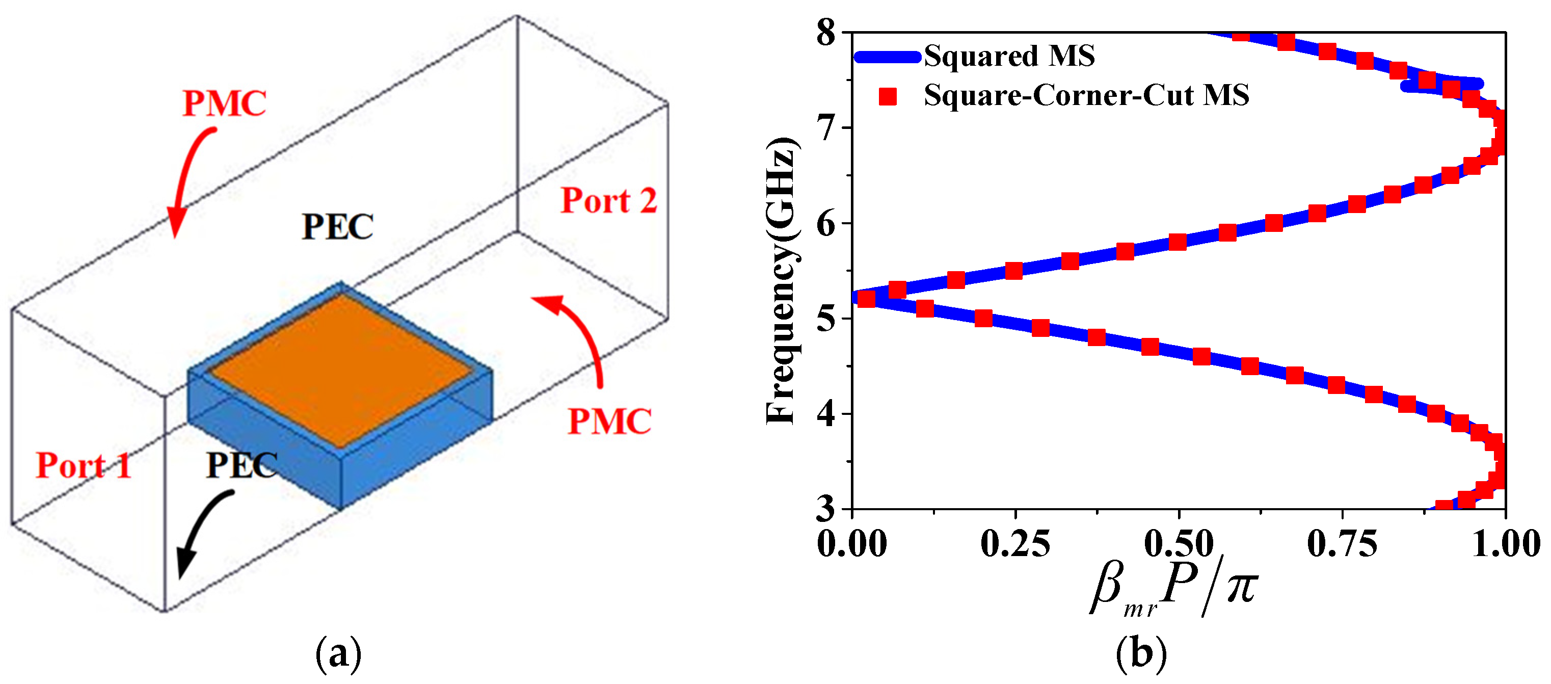
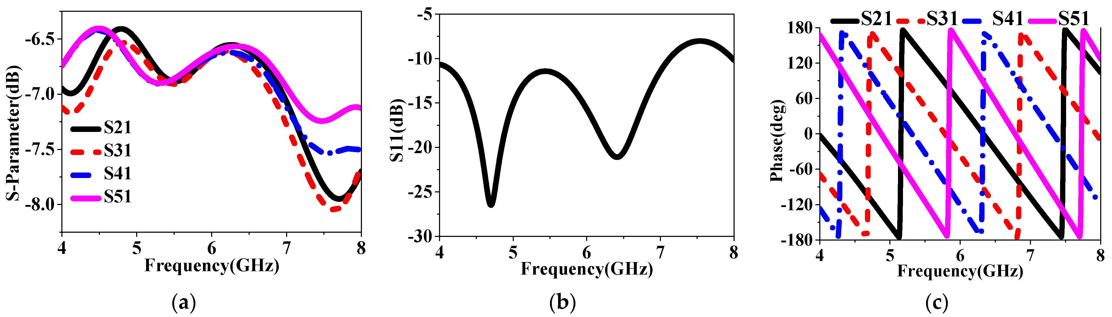
2.2. Analysis of LCPC Unit Cell and Hybrid MS Design
2.3. LHCP IHMS–Antenna Design and Analysis
3. Antennas Analysis
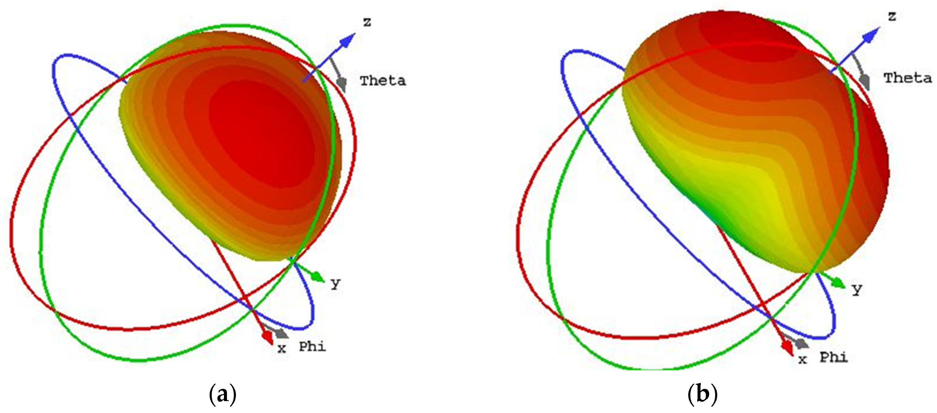
3.1. Analysis of the Mode Behaviors of the Two HMSA-Based Antenna Using CMA
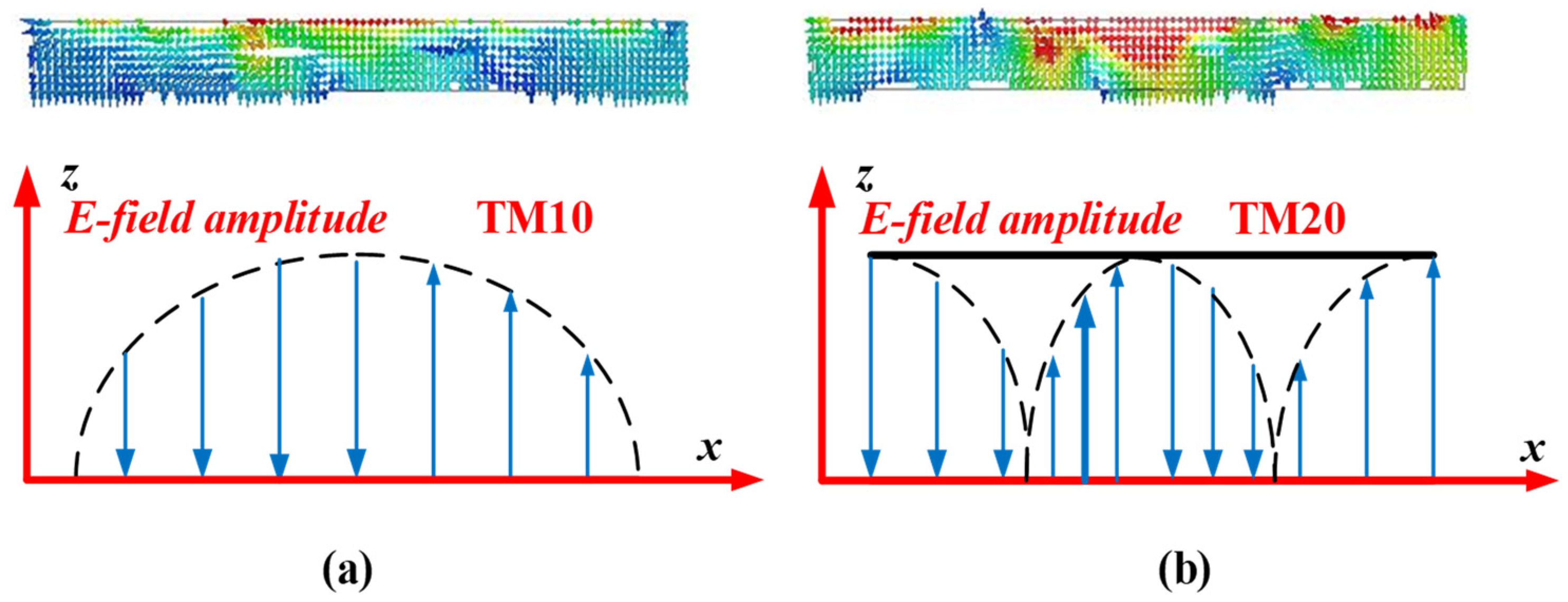
3.2. E-Field Analysis for the Three MS-Based Antennas
4. Radiating Mechanism of the IHMSA
5. Simulated and Measured Results
6. Conclusions
Author Contributions
Funding
Institutional Review Board Statement
Informed Consent Statement
Data Availability Statement
Conflicts of Interest
References
- Li, K.; Liu, Y.; Jia, Y.; Guo, Y.J. A circularly polarized high gain antenna with low RCS over a wideband using chessboard polarization conversion metasurfaces. IEEE Trans. Antennas Propag. 2017, 65, 4288–4292. [Google Scholar] [CrossRef]
- Tran-Huy, H.; Nguyen, H.-H.; Phuong, T.H.T. A compact metasurface-based circularly polarized antenna with high gain and high front-to-back ratio for RFID readers. PLoS ONE 2023, 18, e0288334. [Google Scholar] [CrossRef]
- Xu, H.-X.; Shao, Y.; Luo, H.; Wang, Y.; Wang, C. Janus Reflective Polarization-Division Metadevices with Versatile Functions. IEEE Trans. Microw. Theory Tech. 2023, 71, 3273–3283. [Google Scholar] [CrossRef]
- Liu, T.; Liu, L.; Chen, H.; Sun, H.; Jin, Z.; Chernogor, L.F.; Batrakov, D.O.; Sun, Z. A broadband circularly polarized antenna based on transparent conformal metasurface. IEEE Antennas Wirel. Propag. Lett. 2023, 22, 3197–3201. [Google Scholar] [CrossRef]
- Xu, H.X.; Wang, S.; Wang, C.; Wang, M.; Wang, Y.; Peng, Q. Polarization-insensitive metalens and its applications to reflectarrays with polarization diversity. IEEE Trans. Antennas Propag. 2021, 70, 1895–1905. [Google Scholar] [CrossRef]
- Chen, Q.; Zhang, H. Dual-Patch Polarization Conversion Metasurface-Based Wideband Circular Polarization Slot Antenna. IEEE Access 2018, 6, 74772–74777. [Google Scholar] [CrossRef]
- Xu, H.X.; Hu, G.; Kong, X.; Shao, Y.; Genevet, P.; Qiu, C.W. Super-reflector enabled by non-interleaved spin-momentum-multiplexed metasurface. Light Sci. Appl. 2023, 12, 78. [Google Scholar] [CrossRef]
- Chen, Q.; Zhang, H. High-Gain Circularly Polarized Fabry-Pérot Patch Array Antenna with Wideband Low-Radar-Cross-Section Property. IEEE Access 2019, 7, 8885–8889. [Google Scholar] [CrossRef]
- Wang, P.; Jia, Y.; Hu, W.; Liu, Y.; Lei, H.; Sun, H.; Cui, T.J. Circularly polarized polarization conversion metasurface-inspired antenna array with low RCS over a wide band. IEEE Trans. Antennas Propag. 2023, 71, 5626–5636. [Google Scholar] [CrossRef]
- Li, X.F.; Wang, G.M.; Zou, X.J.; Li, T.J.; Cai, T. Broadband circularly polarized folded transmitarray antenna based on polarization conversion metasurfaces. AEU-Int. J. Electron. Commun. 2023, 163, 154596. [Google Scholar] [CrossRef]
- Wang, J.; Cheng, Y.; Luo, H.; Chen, F.; Wu, L. High-gain bidirectional radiative circularly polarized antenna based on focusing metasurface. AEU-Int. J. Electron. Commun. 2022, 151, 154222. [Google Scholar] [CrossRef]
- Supreeyatitikul, N.; Boonpoonga, A.; Phongcharoenpanich, C. Z-shaped metasurface-based wideband circularly polarized Fabry–Pérot antenna for C-band satellite technology. IEEE Access 2022, 10, 59428–59441. [Google Scholar] [CrossRef]
- Qu, M.; Li, S. A nonuniform metasurface loaded circularly polarized differentially fed antenna. Electromagnetics 2019, 39, 582–593. [Google Scholar] [CrossRef]
- Le, T.T.; Kim, Y.D.; Yun, T.Y. All-Textile Enhanced-Bandwidth Polarization-Conversion Antenna Using a Non-Uniform Metasurface. IEEE Antennas Wirel. Propag. Lett. 2023, 22, 2432–2436. [Google Scholar] [CrossRef]
- Guthi, S. Broadband and high gain circularly polarized mushroom-loaded nonuniform patch array antenna with aperture CPW feed. Microw. Opt. Technol. Lett. 2023, 65, 2565–2571. [Google Scholar] [CrossRef]
- Chen, Q.; Yang, J.; He, C.; Hong, L.; Zhang, D.; Huang, S.; Yu, F.; Zhang, L.; Zhang, H. Nonuniform metasurface for wideband circularly polarized antenna using characteristic mode analysis. AEU-Int. J. Electron. Commun. 2023, 172, 154978. [Google Scholar] [CrossRef]
- Dicandia, F.A.; Genovesi, S. Characteristic modes analysis of non-uniform metasurface superstrate for nanosatellite antenna design. IEEE Access 2020, 8, 176050–176061. [Google Scholar] [CrossRef]
- Gao, X.; Yin, S.; Wang, G.; Xue, C.; Xie, X. Broadband low-RCS circularly polarized antenna realized by nonuniform metasurface. IEEE Antennas Wirel. Propag. Lett. 2022, 21, 2417–2421. [Google Scholar] [CrossRef]
- Cui, J.; Zhao, X.; Sheng, W. Low profile and broadband circularly polarized metasurface antenna based on nonuniform array. AEU-Int. J. Electron. Commun. 2022, 156, 154386. [Google Scholar] [CrossRef]
- Xie, P.; Wang, G.; Li, H.; Liang, J.; Gao, X. Circularly polarized Fabry–Perot antenna employing a receiver-transmitter polarization conversion metasurface. IEEE Trans. Antennas Propag. 2019, 68, 3213–3218. [Google Scholar] [CrossRef]
- Ta, S.X.; Park, I. Low-profile broadband circularly polarized patch antenna using metasurface. IEEE Trans. Antennas Propag. 2015, 63, 5929–5934. [Google Scholar] [CrossRef]
- Zhang, Y.; Xu, F. A low profile metasurface-based circularly polarized antenna. Int. J. RF Microw. Comput.-Aided Eng. 2022, 32, e23031. [Google Scholar] [CrossRef]
- Yuan, Z. A metasurface-enabled Fabry–Pérot (FP) circularly polarized antenna with continuous wideband polarization conversion purity. Frequenz 2021, 75, 341–348. [Google Scholar] [CrossRef]
- Mu, Z.H.; Ma, J.N.; Zhao, Y.J.; Liang, S.; Chen, C.X. Wideband low radar cross section circularly polarized array antenna based on metasurface and sequential phase feed. Int. J. RF Microw. Comput.-Aided Eng. 2021, 31, e22639. [Google Scholar] [CrossRef]
- Chen, Q.; Zhang, H.; Shao, Y.-J.; Zhong, T. Bandwidth and Gain Improvement of an L-Shaped Slot Antenna with Metamaterial Loading. IEEE Antennas Wirel. Propag. Lett. 2018, 17, 1411–1415. [Google Scholar] [CrossRef]
- Zhu, H.L.; Cheung, S.W.; Chung, K.L.; Yuk, T.I. Linear-to-circular polarization conversion using metasurface. IEEE Trans. Antennas Propag. 2013, 61, 4615–4623. [Google Scholar] [CrossRef]
- Juan, Y.; Yang, W.; Che, W. Miniaturized low-profile circularly polarized metasurface antenna using capacitive loading. IEEE Trans. Antennas Propag. 2019, 67, 3527–3532. [Google Scholar] [CrossRef]
- Dong, J.; Ding, C.; Mo, J. A low-profile wideband linear-to-circular polarization conversion slot antenna using metasurface. Materials 2020, 13, 1164. [Google Scholar] [CrossRef]
- Aziz, R.S.; Koziel, S. Circularly polarized metalens antenna design for 5G NR sub-6 GHz communication systems. AEU-Int. J. Electron. Commun. 2024, 173, 155024. [Google Scholar] [CrossRef]


| Dimension | Size (mm) | Dimension | Size (mm) |
|---|---|---|---|
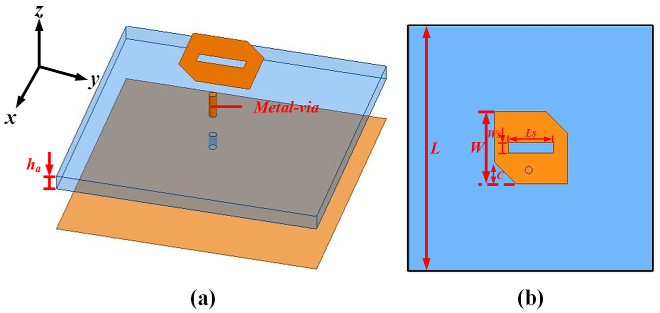
| ha | 3.175 | L | 55 |
| Ws | 2 | C | 5.3 |
| Ls | 12 | W | 16.25 |
| g | 1 | Lpx | 7.625 |
| Wsy | 1.5 | Lsx | 7 |
| Cs | 3 |
| Types of Antennas | Structure | S11 (GHz) | 3 dB AR (GHz) | Peak Gain (dBic) |
|---|---|---|---|---|
| LHCP ANTENNA | just 90° rotated IHMS-based | 4.25–8.48 | 4.62–5.46 | 9.4 |
| RHCP ANTENNA | IHMS-based | 4.1–7.1 | 4.4–6.2 | 9.94 |
| Ref. | Source Antenna Type | MS Type | Center Frequency (GHz) | Size (λ03) | 3 dB AR BW (GHz) | Peak Gain (dBic) | 3 dB AR Angle Range | Operating Bandwidth (GHz) |
|---|---|---|---|---|---|---|---|---|
| Proposed | slot patch | Hybrid | 5.175 | 1.79 × 1.79 × 0.09 | 4–6.35 (45.4%) | 15.1 | −30° to 30° | 4–6.35 (45.4%) |
| [18] | slot patch | Hybrid | 8.45 | 2 × 2 × 0.08 | 7–9.78 (33.13%) | 13.17 | −8° to 10° | 6.05–10.04 (49.6%) |
| [19] | Slot Patch | Nonuniform | 1.75 | 0.67 × 0.67 × 0.06 | 1.3–2.1 (47%) | 8.7 | −21° to 18° | 1.4–2.1 (40%) |
| [20] | patch | uniform | 10.2 | 2.6 × 2.63 × 0.36 | 9.8–10.2 (4%) | 17.8 | −15° to 15° | 9.78–10.26 (4.79%) |
| [17] | Oblique slot patch | Nonuniform | 2.145 | 2.0 × 2.0 × 0.68 | 2–2.25 (11.7%) | 7.1 | −28° to 28° | 2–2.29 (13.6%) |
| [25] | L-shaped slot Patch | Uniform | 6.85 | 2.0 × 2.0 × 0.88 | 1.36 × 1.36 × 0.08 | 10.5 | −12° to 15° | 5.2–8.5 (48.2%) |
| [26] | slot patch | Uniform | 2.485 | 0.99 × 0.99 × 0.05 | 2.38–2.56 (7.3%) | 10.01 | - | 2.27–2.7 (17.6%) |
| [27] | slot patch | Uniform | 3.42 | 0.58 × 0.58 × 0.043 | 3.33–3.63 (8.5%) | 6.57 | - | 3.02–3.82 |
| [28] | slot patch | Uniform | 5.32 | 0.65 × 0.65 × 0.06 | 5.18–6.19 (17.77%) | 6.3 | - | 4.28–6.37 (39.25%) |
| [29] | slot patch | Nonuniform | 5.6 | 0.56 × 0.56 × 0.076 | (4.9–5.6) 12.78% | 13.4 | - | (5.0–6.3) 21.52 |
Disclaimer/Publisher’s Note: The statements, opinions and data contained in all publications are solely those of the individual author(s) and contributor(s) and not of MDPI and/or the editor(s). MDPI and/or the editor(s) disclaim responsibility for any injury to people or property resulting from any ideas, methods, instructions or products referred to in the content. |
© 2024 by the authors. Licensee MDPI, Basel, Switzerland. This article is an open access article distributed under the terms and conditions of the Creative Commons Attribution (CC BY) license (https://creativecommons.org/licenses/by/4.0/).
Share and Cite
Chen, Q.; Yang, J.; He, C.; Zhang, D.; Huang, S.; Wang, M.; Yu, F.; Dai, G. Wideband Circularly Polarization and High-Gain of a Slot Patch Array Antenna Realized by a Hybrid Metasurface. Sensors 2024, 24, 3510. https://doi.org/10.3390/s24113510
Chen Q, Yang J, He C, Zhang D, Huang S, Wang M, Yu F, Dai G. Wideband Circularly Polarization and High-Gain of a Slot Patch Array Antenna Realized by a Hybrid Metasurface. Sensors. 2024; 24(11):3510. https://doi.org/10.3390/s24113510
Chicago/Turabian StyleChen, Qiang, Jun Yang, Changhui He, Di Zhang, Siyu Huang, Min Wang, Fangli Yu, and Guanghua Dai. 2024. "Wideband Circularly Polarization and High-Gain of a Slot Patch Array Antenna Realized by a Hybrid Metasurface" Sensors 24, no. 11: 3510. https://doi.org/10.3390/s24113510
APA StyleChen, Q., Yang, J., He, C., Zhang, D., Huang, S., Wang, M., Yu, F., & Dai, G. (2024). Wideband Circularly Polarization and High-Gain of a Slot Patch Array Antenna Realized by a Hybrid Metasurface. Sensors, 24(11), 3510. https://doi.org/10.3390/s24113510