
The Accuracy of Evaluation of the Requirements of the Standards IEC 61000-3-2(12) with the Application of the Wideband Current Transducer


Abstract
1. Introduction
2. The Standards IEC 61000-3-2 and IEC 61000-3-12
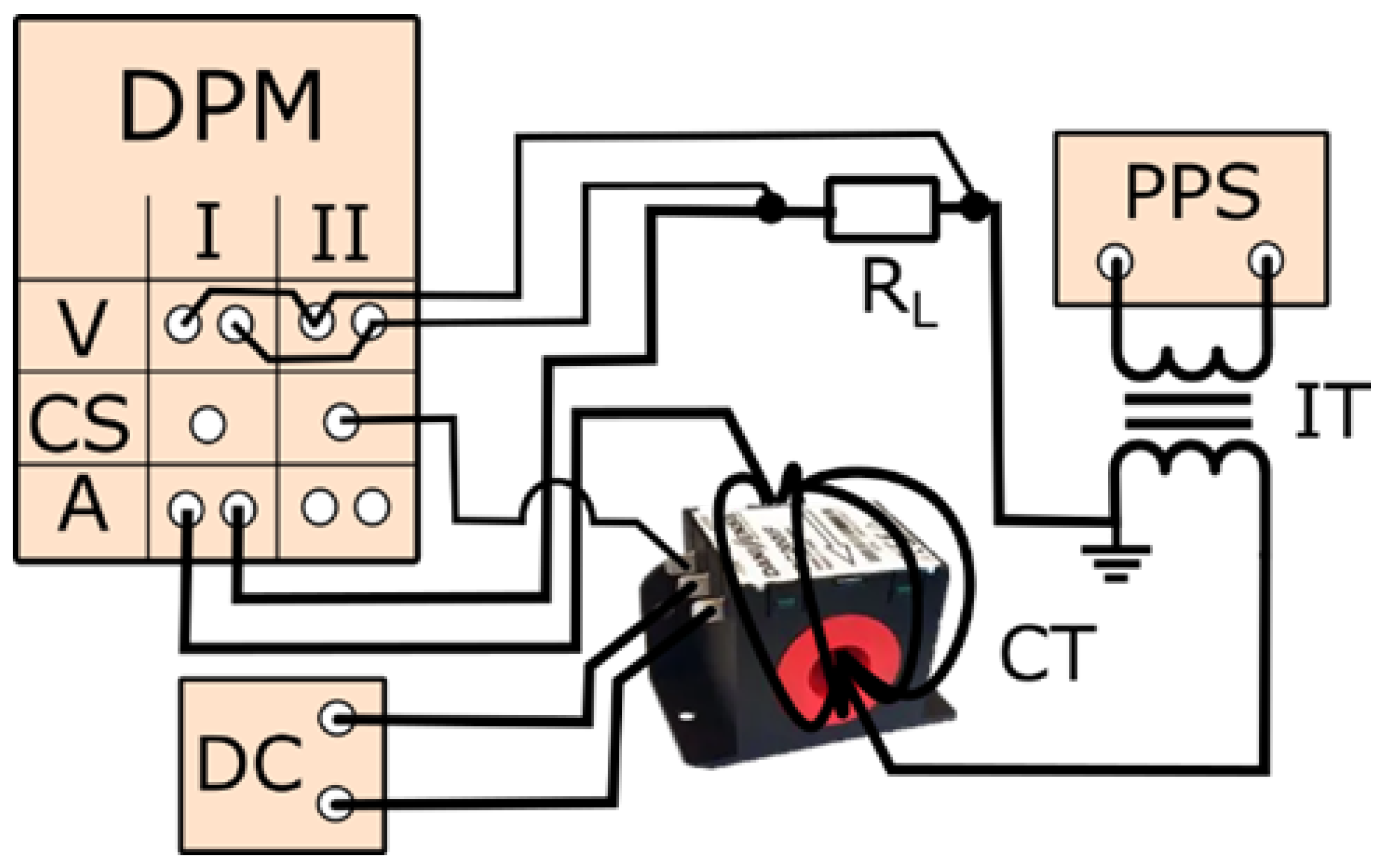
3. The Objects of the Research and the Measuring Setup
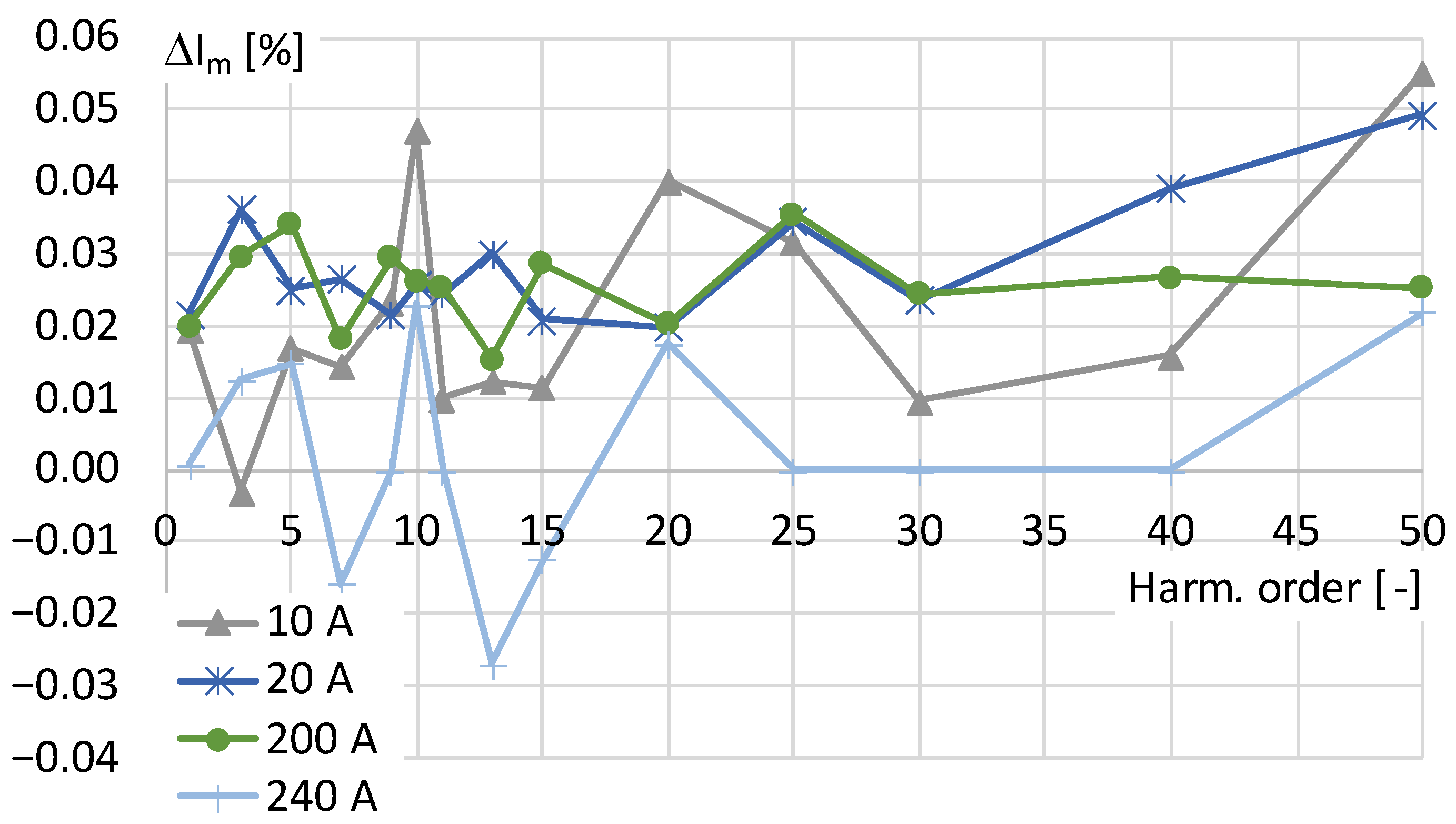
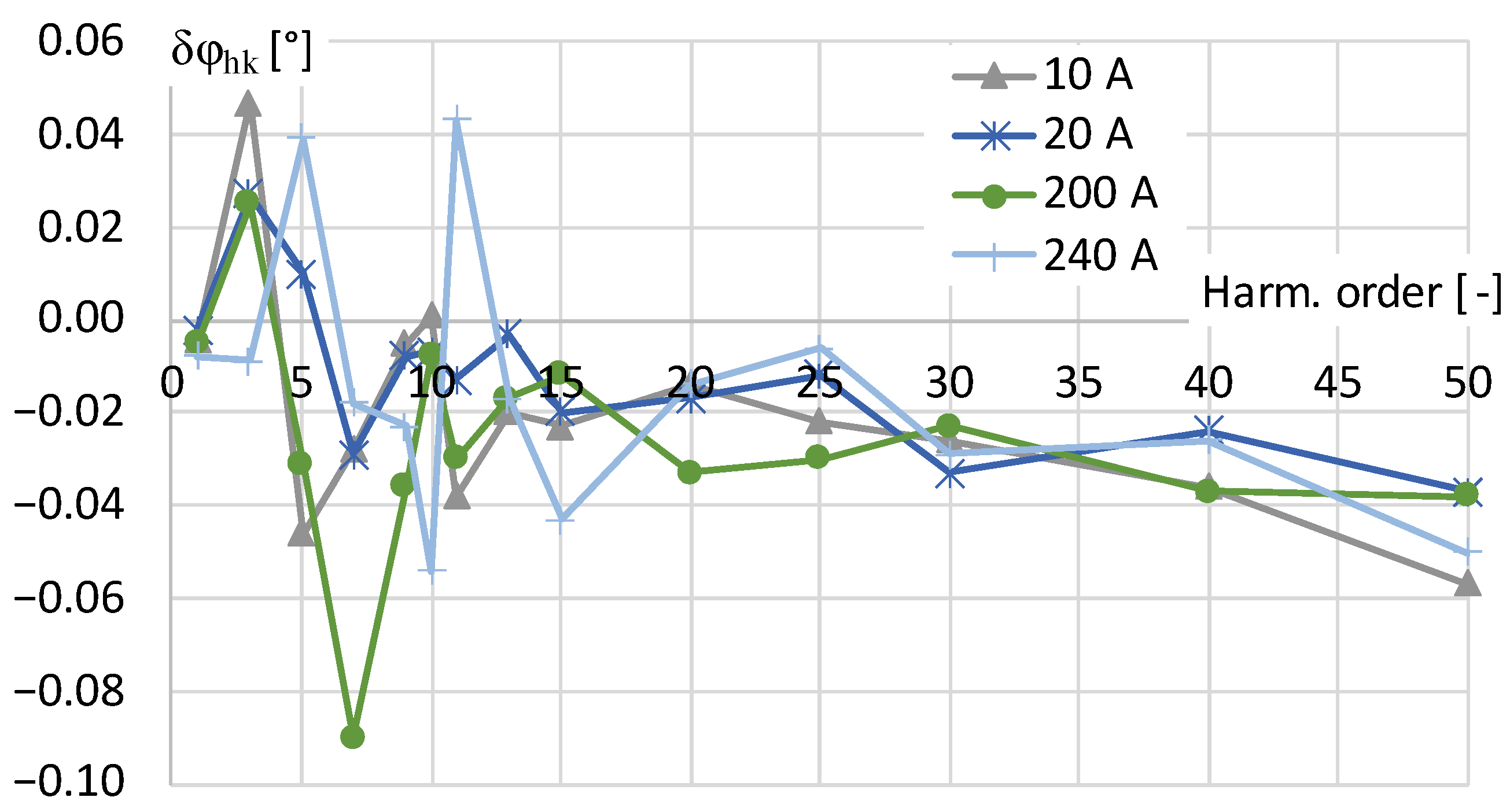
4. Results
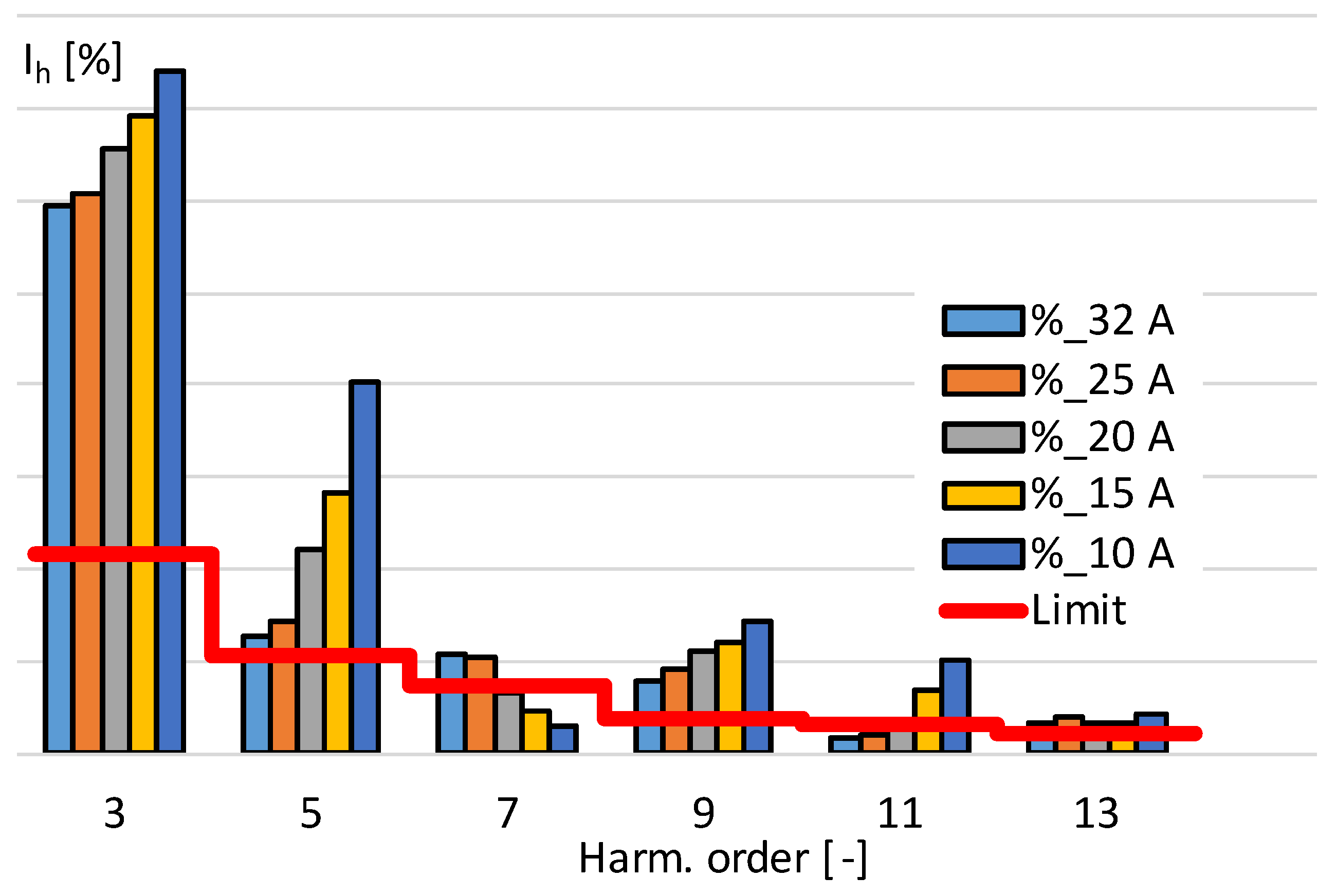
5. Application
6. Conclusions
Author Contributions
Funding
Institutional Review Board Statement
Informed Consent Statement
Data Availability Statement
Conflicts of Interest
References
- Brodecki, D.; Stano, E.; Andrychowicz, M.; Kaczmarek, P. EMC of Wideband Power Sources. Energies 2021, 14, 1457. [Google Scholar] [CrossRef]
- Crotti, G.; D’Avanzo, G.; Landi, C.; Letizia, P.S.; Luiso, M. Evaluation of Voltage Transformers’ Accuracy in Harmonic and Interharmonic Measurement. IEEE Open J. Instrum. Meas. 2022, 1, 1–10. [Google Scholar] [CrossRef]
- Skala, B.; Kindl, V.; Polacek, L.; Turjanica, P.; Vobornik, A.; Valenta, J.; Bachura, V. Design of Current Sensor for Medium Frequency Operation. In Proceedings of the 2020 ELEKTRO, Taormina, Italy, 25–28 May 2020; pp. 1–6. [Google Scholar]
- Yan, P.; Liu, G.; Wang, R.; Xia, B.; Zhang, J.; Yi, L. Development Method and Comparative Analysis of Measurement Accuracy of New Broadband and Wide Range Current Transformers. In Proceedings of the 2022 4th International Conference on Electrical Engineering and Control Technologies (CEECT), Shanghai, China, 16–18 December 2022; pp. 379–384. [Google Scholar]
- So, E.; Arseneau, R.; Bennett, D.; Frigault, M.E. A Current-Comparator-Based System For Calibrating High-Voltage Current Transformers under Actual Operating Conditions. IEEE Trans. Instrum. Meas. 2011, 60, 2449–2454. [Google Scholar] [CrossRef]
- Ripka, P.; Draxler, K.; Styblikova, R. AC/DC Current Transformer with Single Winding. IEEE Trans. Magn. 2014, 50, 1–4. [Google Scholar] [CrossRef]
- IEC 61000-3-12; Electromagnetic Compatibility (EMC)—Part 3-12: Limits—Limits for Harmonic Currents Produced by Equipment Connected to Public Low-Voltage Systems with Input Current >16 A and ≤75 A per Phase. International Electrotechnical Commission: Geneva, Switzerland, 2011.
- IEC 61000-3-2; Amendment 1—Electromagnetic Compatibility (EMC)—Part 3-2: Limits—Limits for Harmonic Current Emissions (Equipment Input Current ≤ 16 A per Phase). International Electrotechnical Commission: Geneva, Switzerland, 2018.
- Draxler, K.; Styblikova, R. Using Instrument Transformers in a Wider Frequency Range. In Proceedings of the Conference Record—IEEE Instrumentation and Measurement Technology Conference, Hangzhou, China, 10–12 May 2011; pp. 1207–1210. [Google Scholar]
- Cataliotti, A.; Cosentino, V.; Crotti, G.; Giordano, D.; Modarres, M.; Di Cara, D.; Tinè, G.; Gallo, D.; Landi, C.; Luiso, M. Metrological Performances of Voltage and Current Instrument Transformers in Harmonics Measurements. In Proceedings of the I2MTC 2018—2018 IEEE International Instrumentation and Measurement Technology Conference: Discovering New Horizons in Instrumentation and Measurement, Proceedings, Houston, TX, USA, 14–17 May 2018; pp. 1–6. [Google Scholar]
- Stano, E.; Kaczmarek, M. Analytical Method to Determine the Values of Current Error and Phase Displacement of Inductive Current Transformers during Transformation of Distorted Currents Higher Harmonics. Measurement 2022, 200, 111664. [Google Scholar] [CrossRef]
- Bassan, F.R.; Rosolem, J.B.; Floridia, C.; Aires, B.N.; Peres, R.; Aprea, J.F.; Nascimento, C.A.M.; Fruett, F. Power-over-Fiber LPIT for Voltage and Current Measurements in the Medium Voltage Distribution Networks. Sensors 2021, 21, 547. [Google Scholar] [CrossRef]
- Mingotti, A.; Costa, F.; Peretto, L.; Tinarelli, R. Accuracy Type Test for Rogowski Coils Subjected to Distorted Signals, Temperature, Humidity, and Position Variations. Sensors 2022, 22, 1397. [Google Scholar] [CrossRef] [PubMed]
- Mingotti, A.; Peretto, L.; Tinarelli, R. Effect of the Conductor Positioning on Low-Power Current Transformers: Inputs for the Next IEC 61869-10. Electricity 2021, 2, 1–12. [Google Scholar] [CrossRef]
- Mingotti, A.; Peretto, L.; Tinarelli, R. A Closed-Form Expression to Estimate the Uncertainty of THD Starting from the LPIT Accuracy Class. Sensors 2020, 20, 1804. [Google Scholar] [CrossRef]
- Mingotti, A.; Peretto, L.; Tinarelli, R. Smart Characterization of Rogowski Coils by Using a Synthetized Signal. Sensors 2020, 20, 3359. [Google Scholar] [CrossRef]
- Cristaldi, L.; Faifer, M.; Laurano, C.; Ottoboni, R.; Toscani, S.; Zanoni, M. A Low-Cost Generator for Testing and Calibrating Current Transformers. IEEE Trans. Instrum. Meas. 2019, 68, 2792–2799. [Google Scholar] [CrossRef]
- Stano, E. The Method to Determine the Turns Ratio Correction of the Inductive Current Transformer. Energies 2021, 14, 8602. [Google Scholar] [CrossRef]
- Mingotti, A.; Peretto, L.; Tinarelli, R.; Angioni, A.; Monti, A.; Ponci, F. A Simple Calibration Procedure for an LPIT plus PMU System under Off-Nominal Conditions. Energies 2019, 12, 4645. [Google Scholar] [CrossRef]
- Crotti, G.; Gallo, D.; Giordano, D.; Landi, C.; Luiso, M.; Cherbaucich, C.; Mazza, P. Low Cost Measurement Equipment for the Accurate Calibration of Voltage and Current Transducers. In Proceedings of the 2014 IEEE International Instrumentation and Measurement Technology Conference (I2MTC) Proceedings, Montevideo, Uruguay, 12–15 May 2014; pp. 202–206. [Google Scholar]
- Jicheng, Y.U.; Dengyun, L.I.; Jun, L.I.; He, L.I.; Zhicheng, L.I. Design and Validation of Broadband Calibration System for Fiber-Optical Current Transformers. J. Phys. Conf. Ser. 2019, 1311, 12026. [Google Scholar] [CrossRef]
- Tong, Y.; Liu, B.; Abu-Siada, A.; Li, Z.; Li, C.; Zhu, B. Research on Calibration Technology for Electronic Current Transformers. In Proceedings of the 2018 Condition Monitoring and Diagnosis (CMD), Perth, Australia, 23–26 September 2018; pp. 1–5. [Google Scholar]
- Faifer, M.; Laurano, C.; Ottoboni, R.; Toscani, S.; Zanoni, M. Harmonic Distortion Compensation in Voltage Transformers for Improved Power Quality Measurements. IEEE Trans. Instrum. Meas. 2019, 68, 3823–3830. [Google Scholar] [CrossRef]
- Filipović-Grčić, D.; Filipović-Grčić, B.; Krajtner, D. Frequency Response and Harmonic Distortion Testing of Inductive Voltage Transformer Used for Power Quality Measurements. Procedia Eng. 2017, 202, 159–167. [Google Scholar] [CrossRef]
- Crotti, G.; Chen, Y.; Çayci, H.; D’Avanzo, G.; Landi, C.; Letizia, P.S.; Luiso, M.; Mohns, E.; Muñoz, F.; Styblikova, R.; et al. How Instrument Transformers Influence Power Quality Measurements: A Proposal of Accuracy Verification Tests. Sensors 2022, 22, 5847. [Google Scholar] [CrossRef] [PubMed]
- Stano, E.; Kaczmarek, P.; Kaczmarek, M. Why Should We Test the Wideband Transformation Accuracy of Inductive Current Transformers? Energies 2022, 15, 5737. [Google Scholar] [CrossRef]
- van den Brom, H.E.; Rietveld, G.; So, E. Sampling Current Ratio Measurement System for Calibration of Current Transducers up to 10 KA with 5·10−6 Uncertainty. IEEE Trans. Instrum. Meas. 2015, 64, 1685–1691. [Google Scholar] [CrossRef]
- Ildarabadi, R.; Zadehbagheri, M. New Technology and Method for Monitoring the Status of Power Systems to Improve Power Quality—A Case Study. Processes 2023, 11, 2468. [Google Scholar] [CrossRef]
- Alhaiz, H.A.; Alsafran, A.S.; Almarhoon, A.H. Single-Phase Microgrid Power Quality Enhancement Strategies: A Comprehensive Review. Energies 2023, 16, 5576. [Google Scholar] [CrossRef]
- Oubrahim, Z.; Amirat, Y.; Benbouzid, M.; Ouassaid, M. Power Quality Disturbances Characterization Using Signal Processing and Pattern Recognition Techniques: A Comprehensive Review. Energies 2023, 16, 2685. [Google Scholar] [CrossRef]


| Min. RSCE | Admissible Individual Harmonic Current Ih/I1 [%] | Admissible Harmonic Parameters [%] | ||||||
|---|---|---|---|---|---|---|---|---|
| I3 | I5 | I7 | I9 | I11 | I13 | THC/I1 | PWHC/I1 | |
| 33 | 21.6 | 10.7 | 7.2 | 3.8 | 3.1 | 2 | 23 | 23 |
| 66 | 24 | 13 | 8 | 5 | 4 | 3 | 26 | 26 |
| 120 | 27 | 15 | 10 | 6 | 5 | 4 | 30 | 30 |
| 250 | 35 | 20 | 13 | 9 | 8 | 6 | 40 | 40 |
| ≥350 | 41 | 24 | 15 | 12 | 10 | 8 | 47 | 47 |
| Harm. Order n | Maximum Permissible Harmonic Current [A] |
|---|---|
| Odd harmonics | |
| 3 | 2.30 |
| 5 | 1.14 |
| 7 | 0.77 |
| 9 | 0.40 |
| 11 | 0.33 |
| 13 | 0.21 |
| 15 ≤ n ≤ 39 | |
| Even harmonics | |
| 2 | 1.08 |
| 4 | 0.43 |
| 6 | 0.30 |
| 8 ≤ n ≤ 40 | |
Disclaimer/Publisher’s Note: The statements, opinions and data contained in all publications are solely those of the individual author(s) and contributor(s) and not of MDPI and/or the editor(s). MDPI and/or the editor(s) disclaim responsibility for any injury to people or property resulting from any ideas, methods, instructions or products referred to in the content. |
© 2024 by the authors. Licensee MDPI, Basel, Switzerland. This article is an open access article distributed under the terms and conditions of the Creative Commons Attribution (CC BY) license (https://creativecommons.org/licenses/by/4.0/).
Share and Cite
Stano, E.; Wiak, S. The Accuracy of Evaluation of the Requirements of the Standards IEC 61000-3-2(12) with the Application of the Wideband Current Transducer. Sensors 2024, 24, 3693. https://doi.org/10.3390/s24113693
Stano E, Wiak S. The Accuracy of Evaluation of the Requirements of the Standards IEC 61000-3-2(12) with the Application of the Wideband Current Transducer. Sensors. 2024; 24(11):3693. https://doi.org/10.3390/s24113693
Chicago/Turabian StyleStano, Ernest, and Slawomir Wiak. 2024. "The Accuracy of Evaluation of the Requirements of the Standards IEC 61000-3-2(12) with the Application of the Wideband Current Transducer" Sensors 24, no. 11: 3693. https://doi.org/10.3390/s24113693
APA StyleStano, E., & Wiak, S. (2024). The Accuracy of Evaluation of the Requirements of the Standards IEC 61000-3-2(12) with the Application of the Wideband Current Transducer. Sensors, 24(11), 3693. https://doi.org/10.3390/s24113693