


New Solid-State Acoustic Motion Sensors: Sensing Potential Estimation for Different Piezo Plate Materials

 , and
, and
Abstract
:1. Introduction
2. Numerical Analysis
2.1. Theoretical Basis
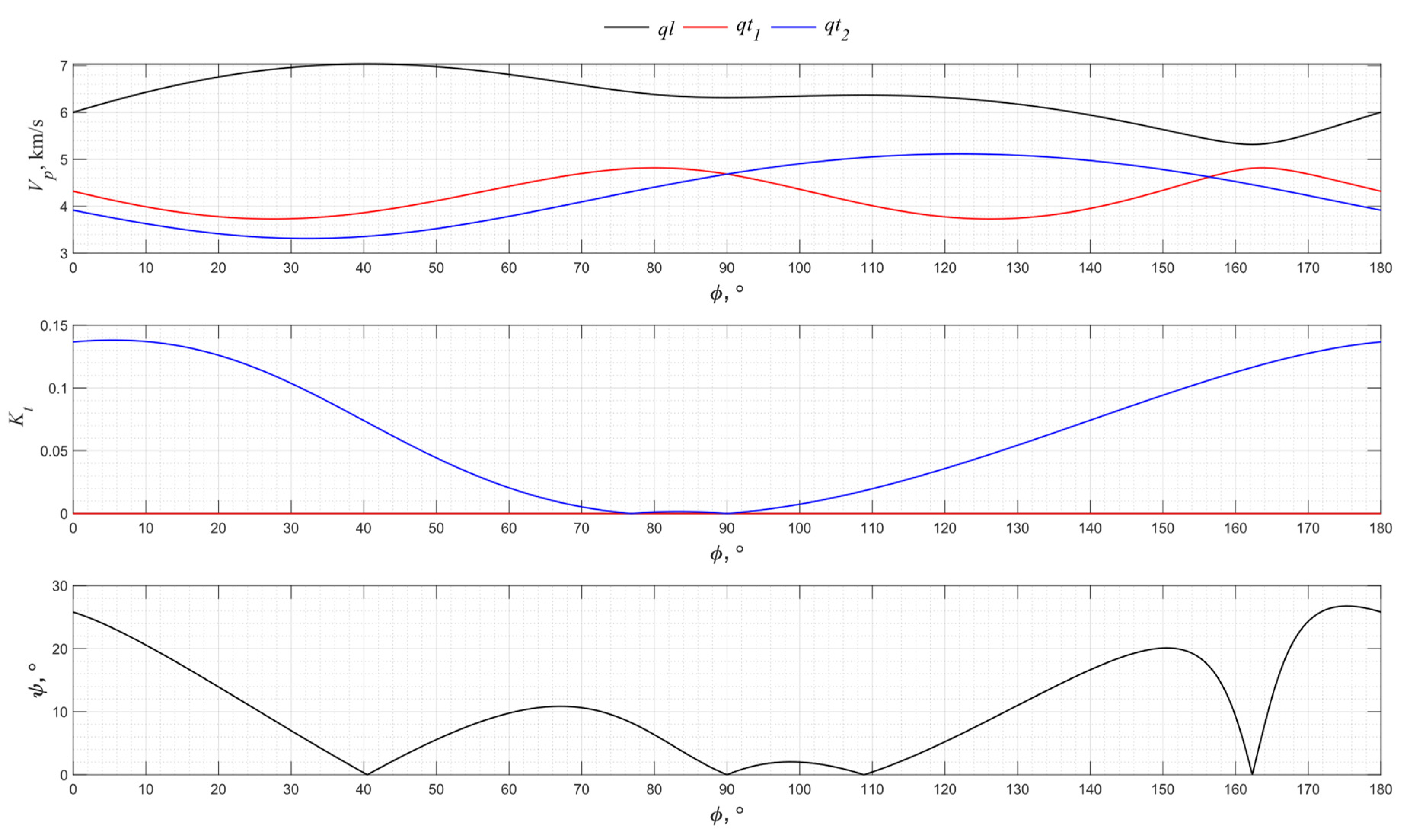
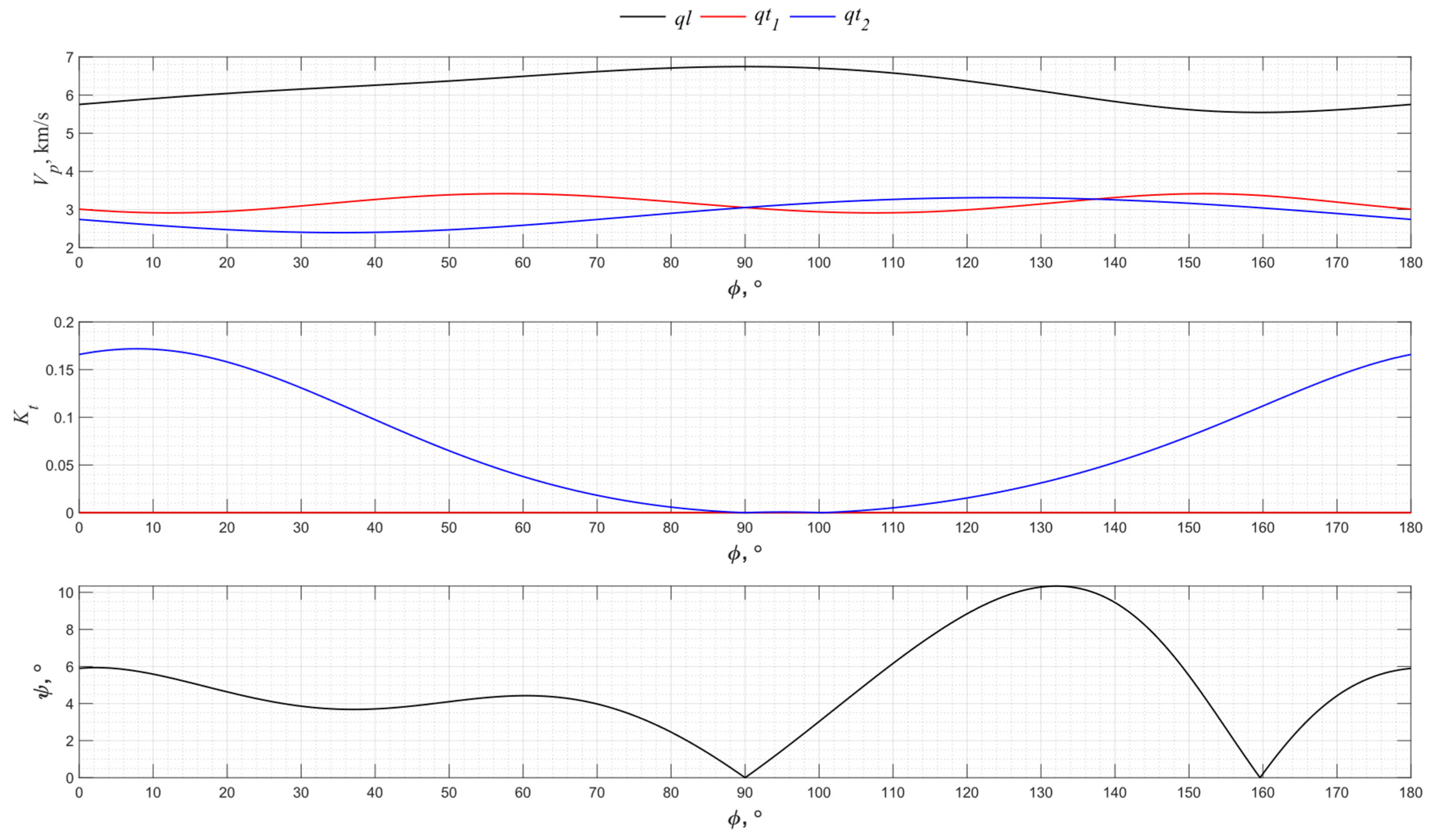
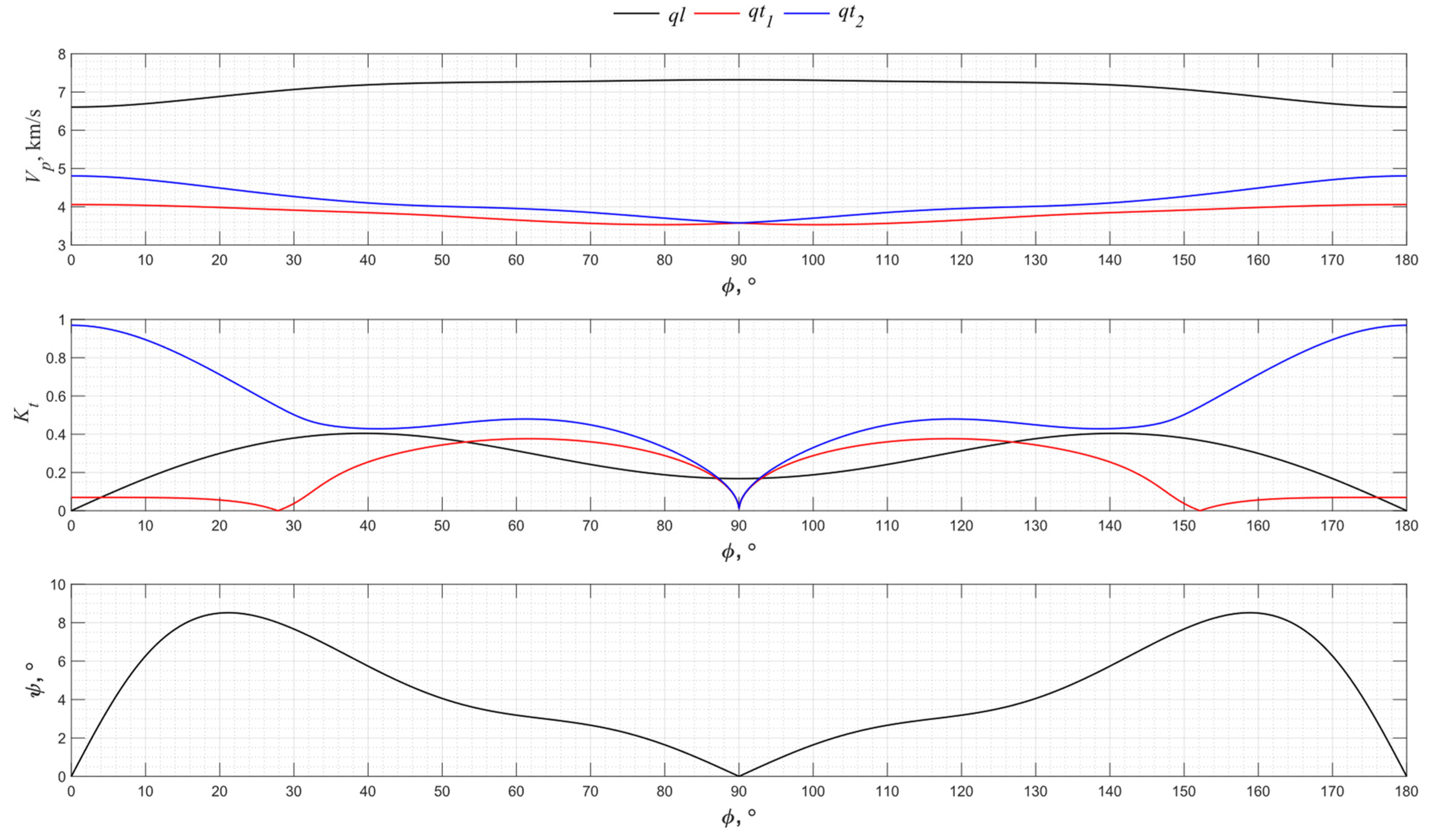
2.2. Piezo Quartz
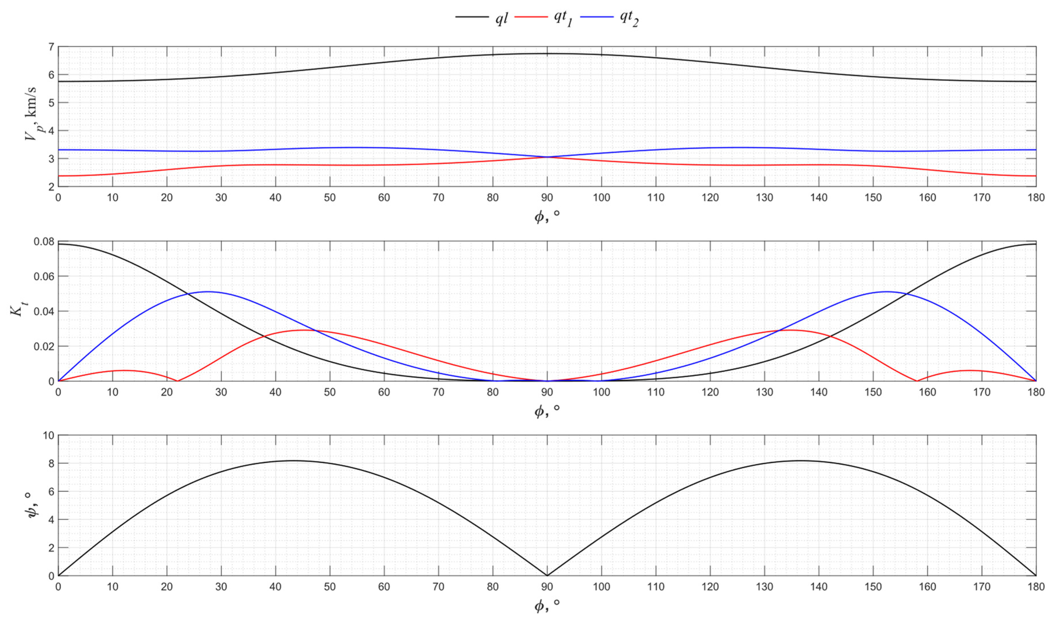
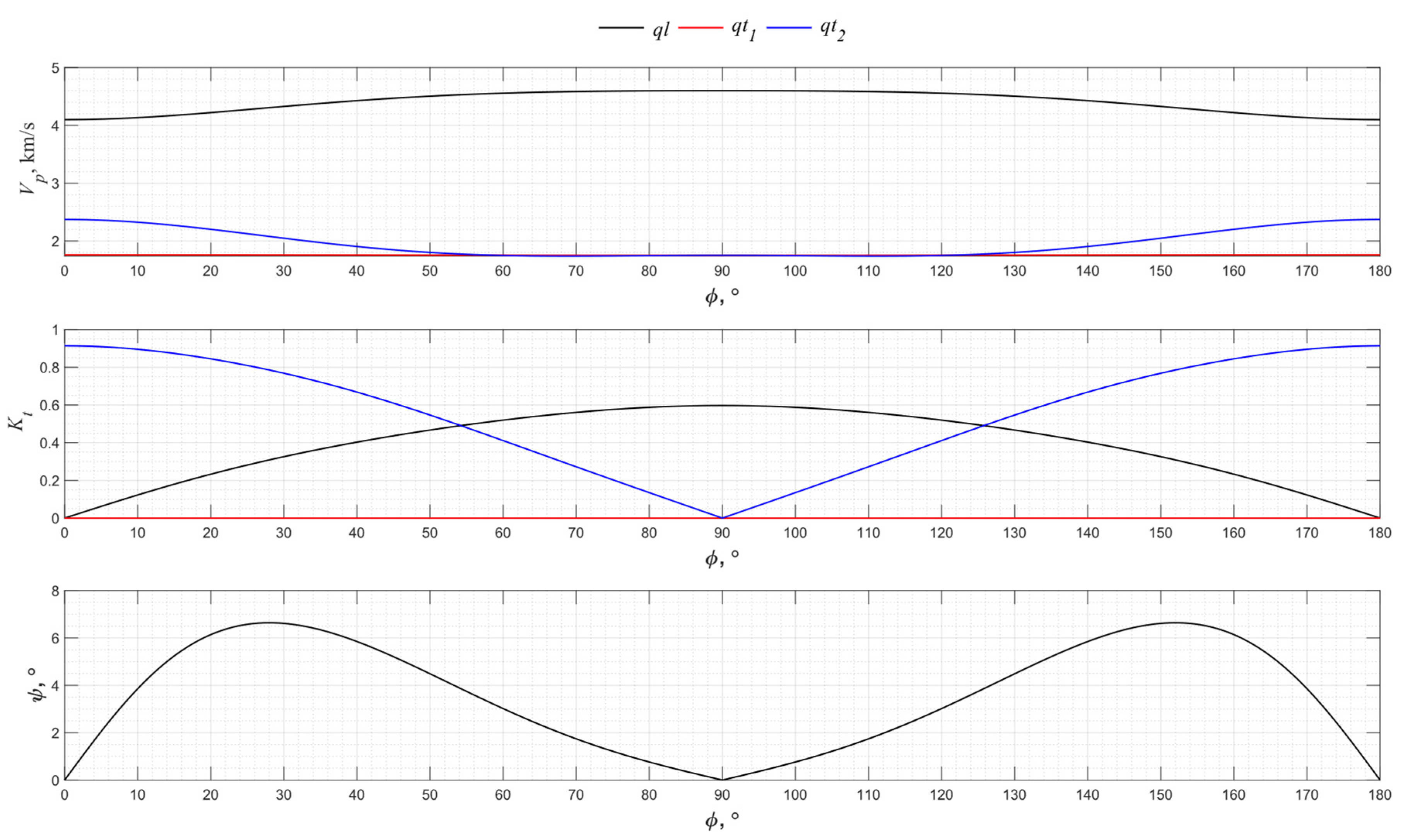
2.3. La3Ga5SiO14
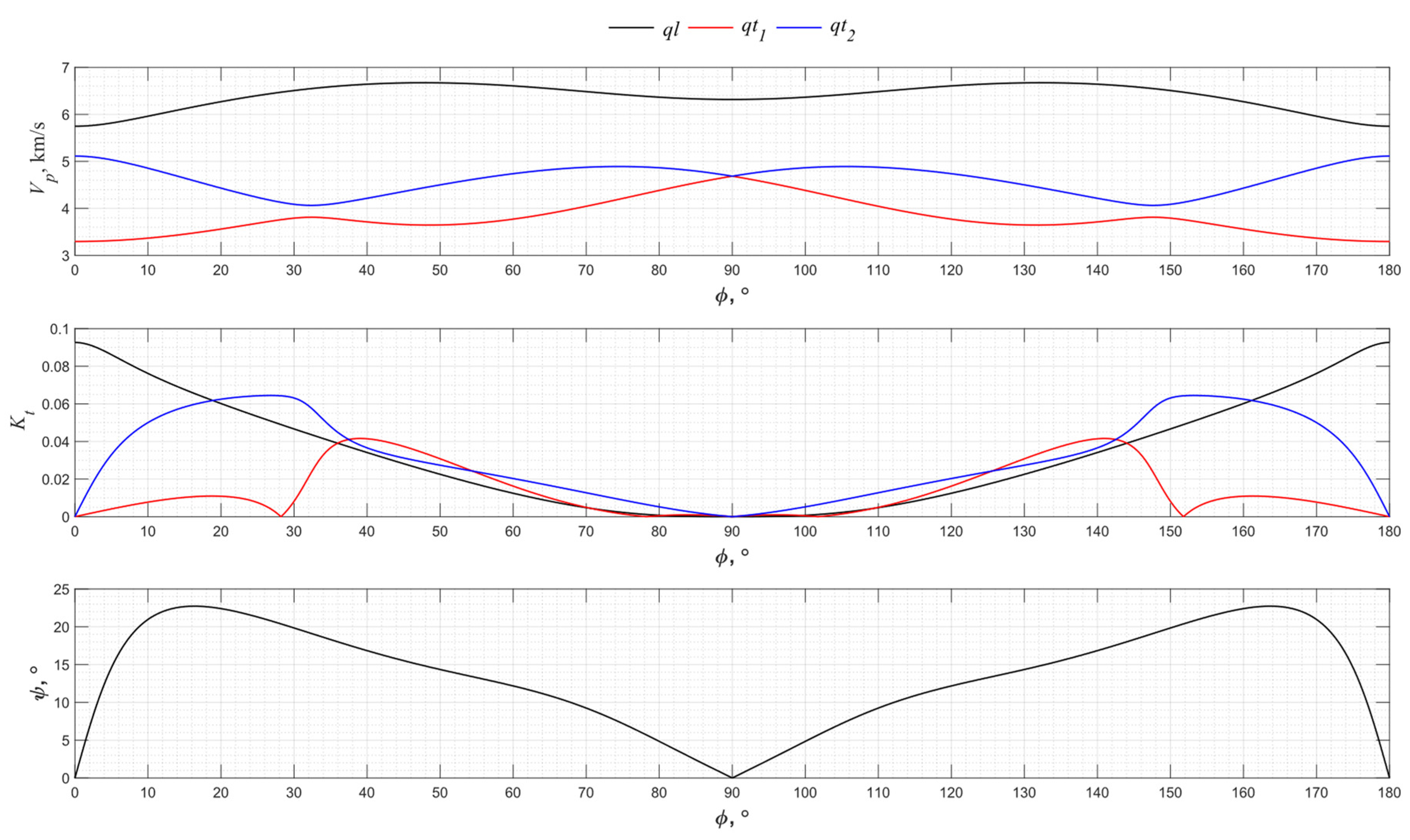
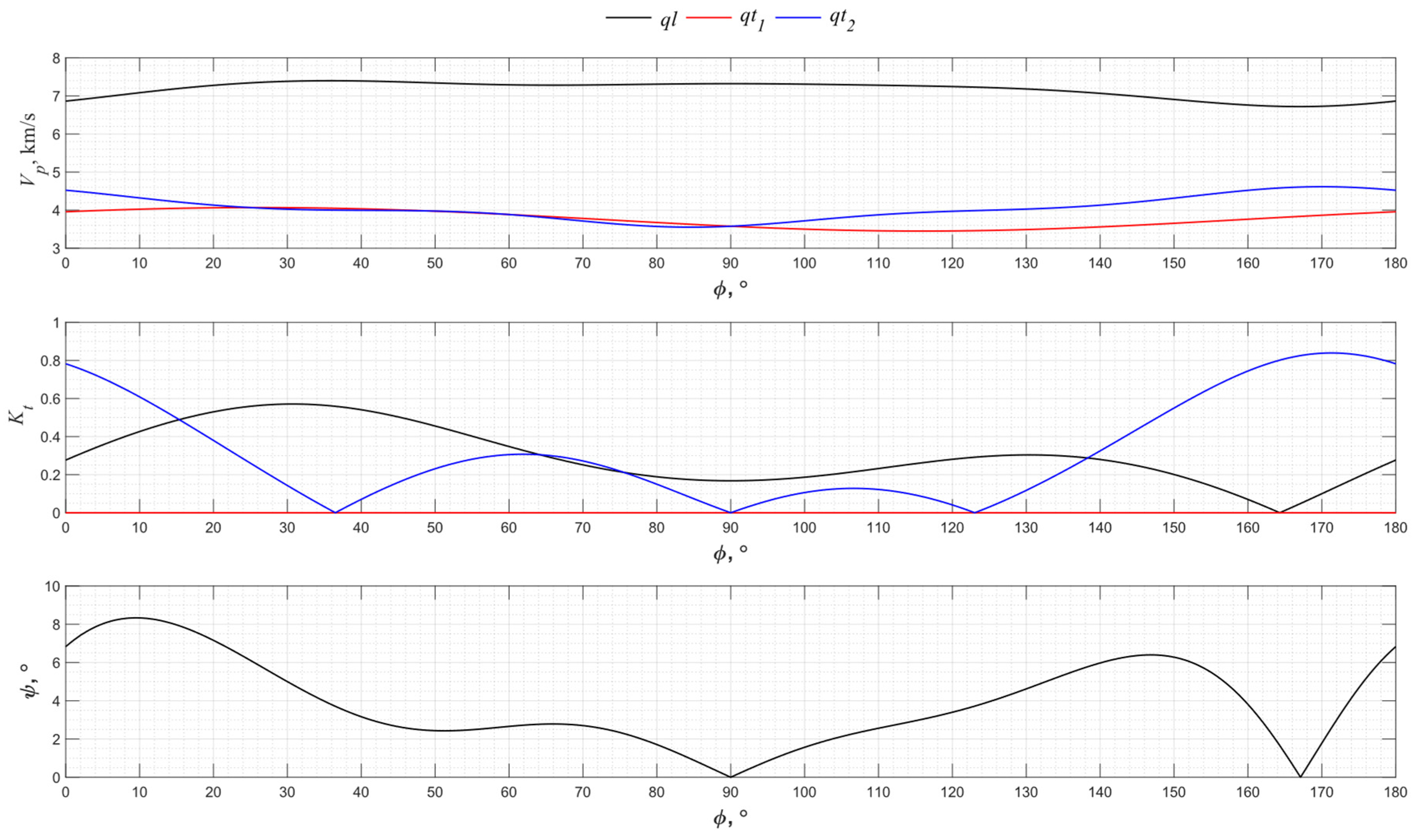
2.4. LiNbO3
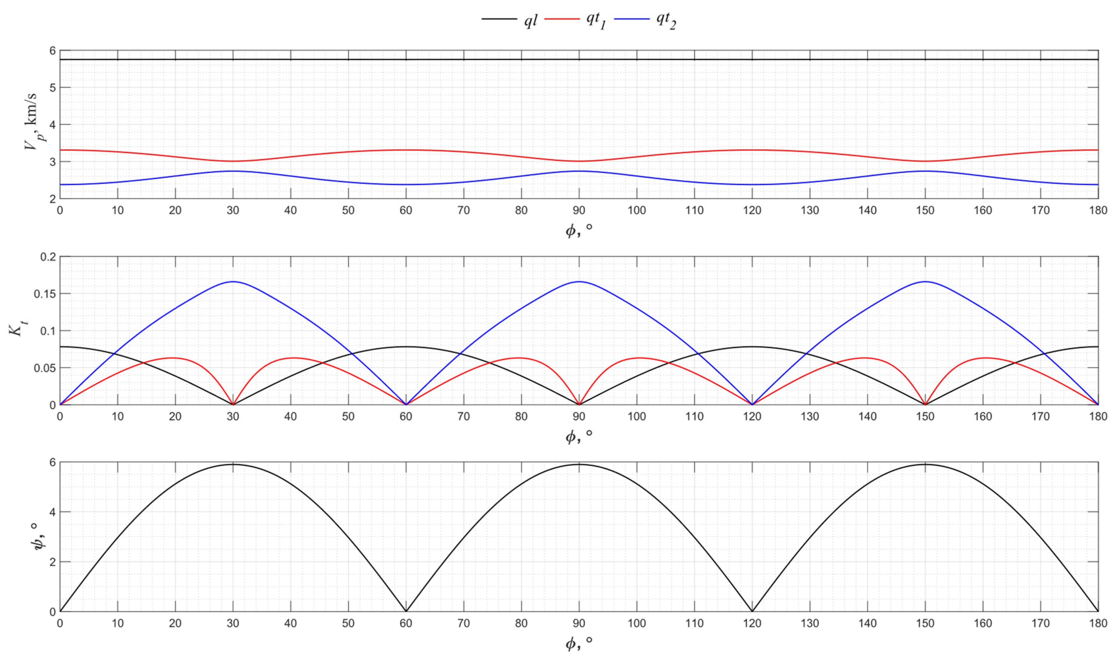
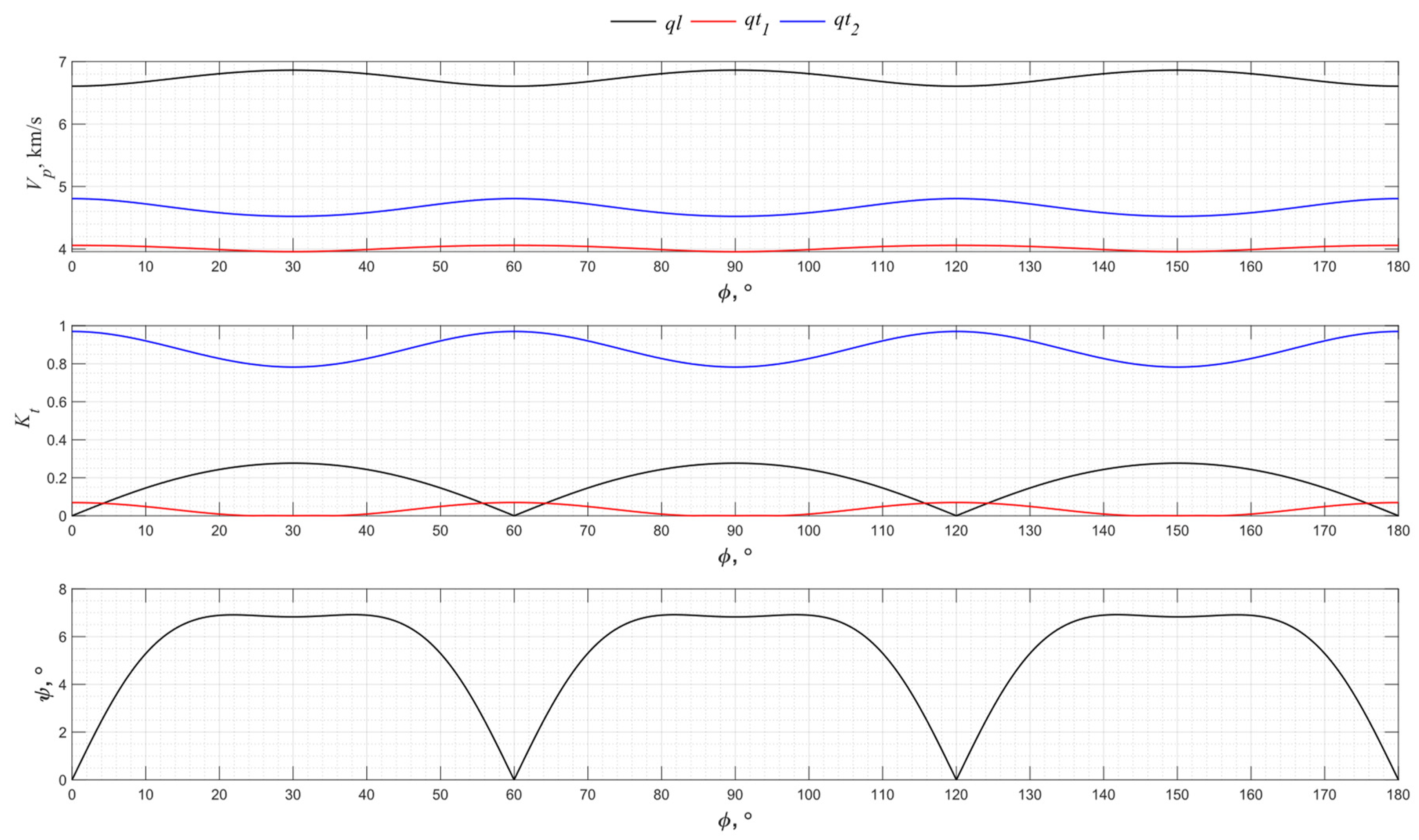
2.5. PZT-5H
2.6. Discussion
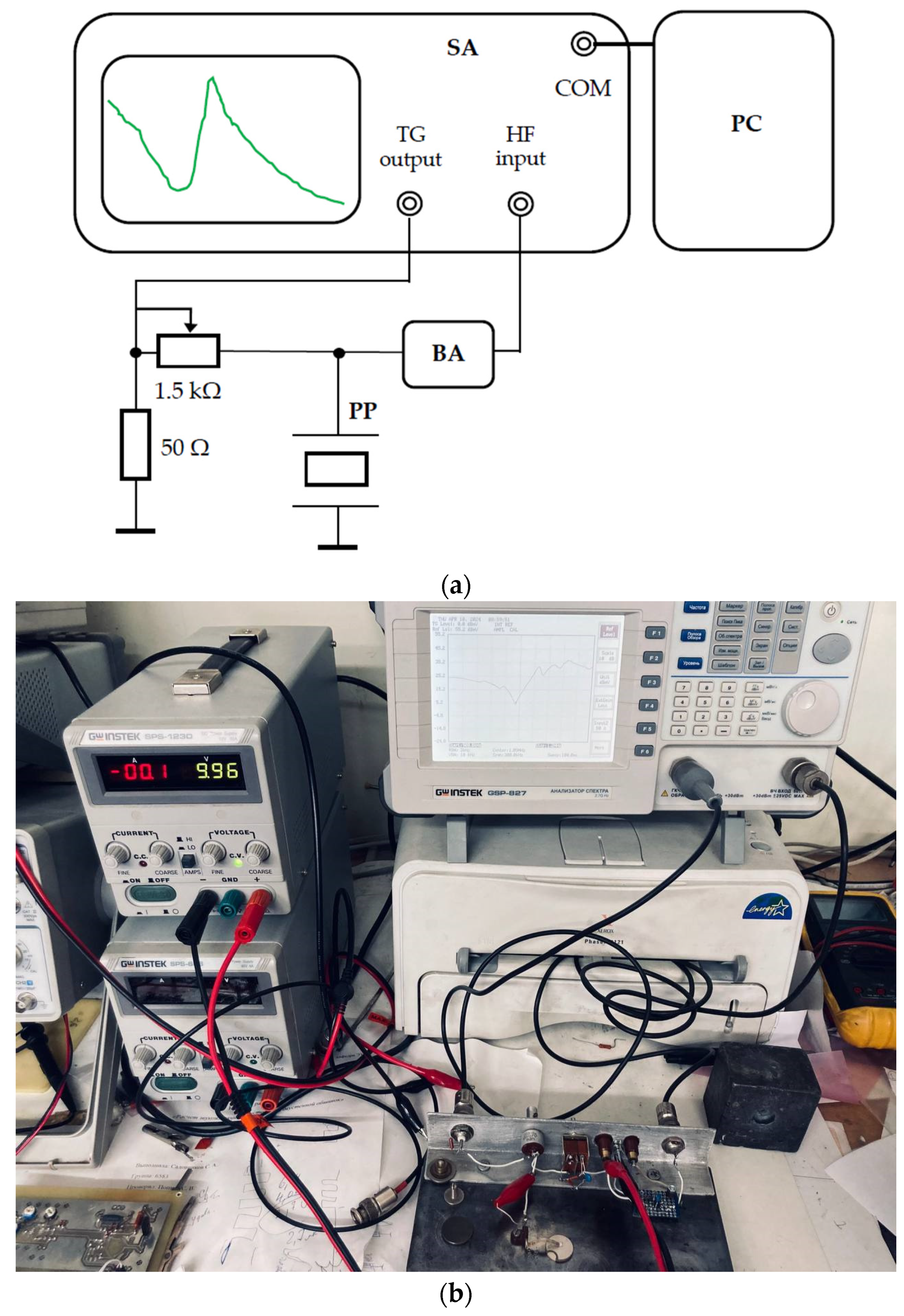
3. Experimental Setup
4. Experimental Results
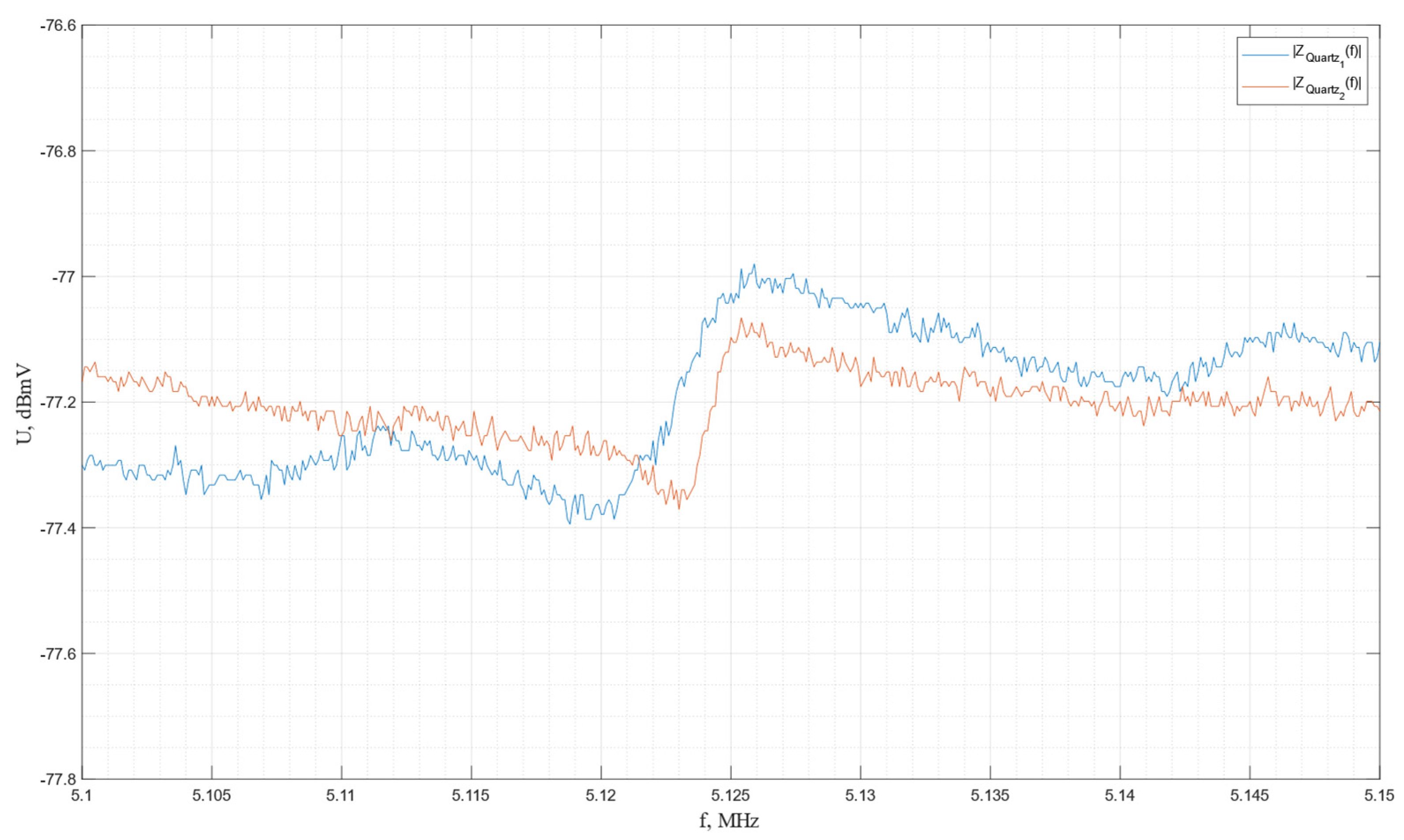
4.1. Piezo Quartz
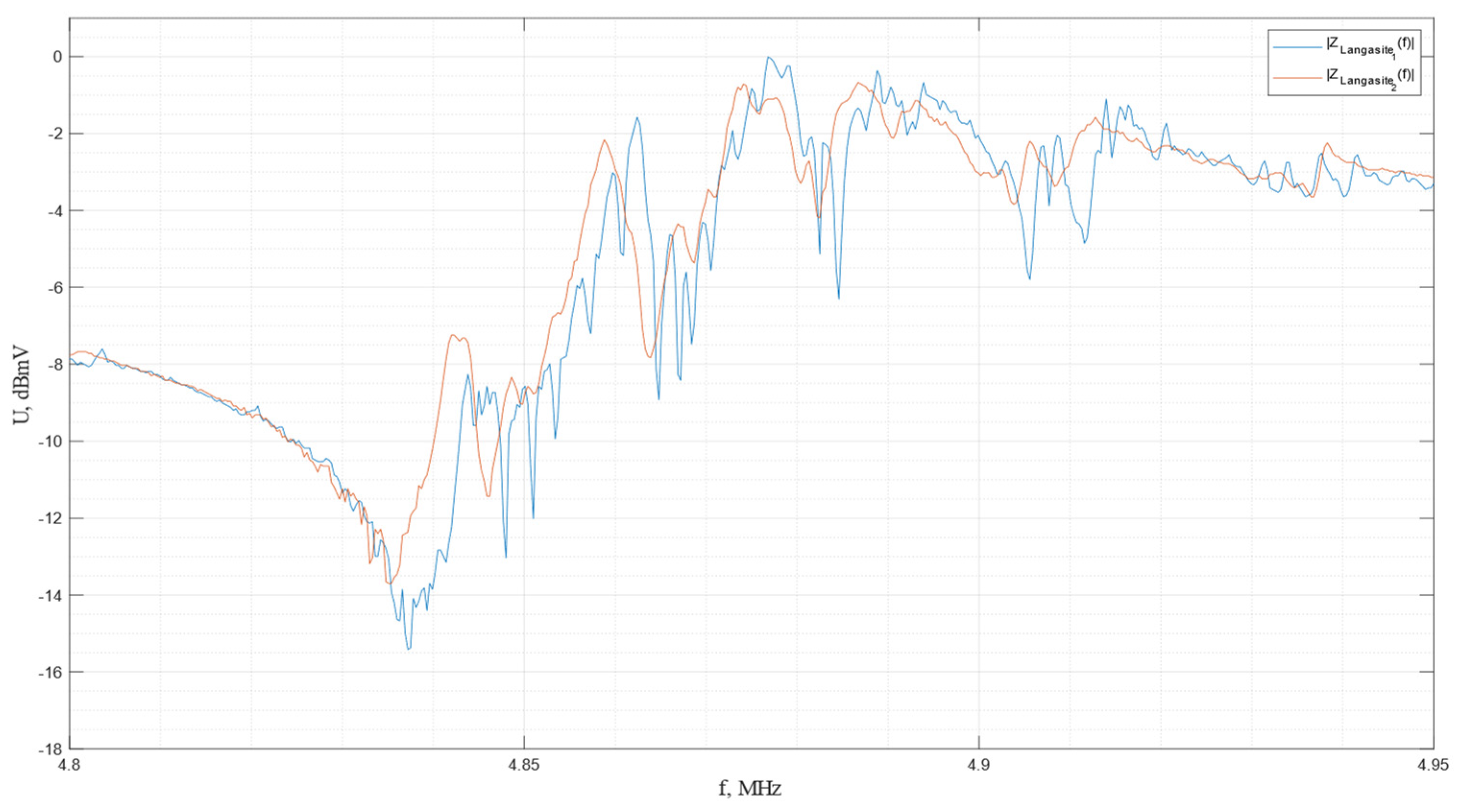
4.2. La3Ga5SiO14
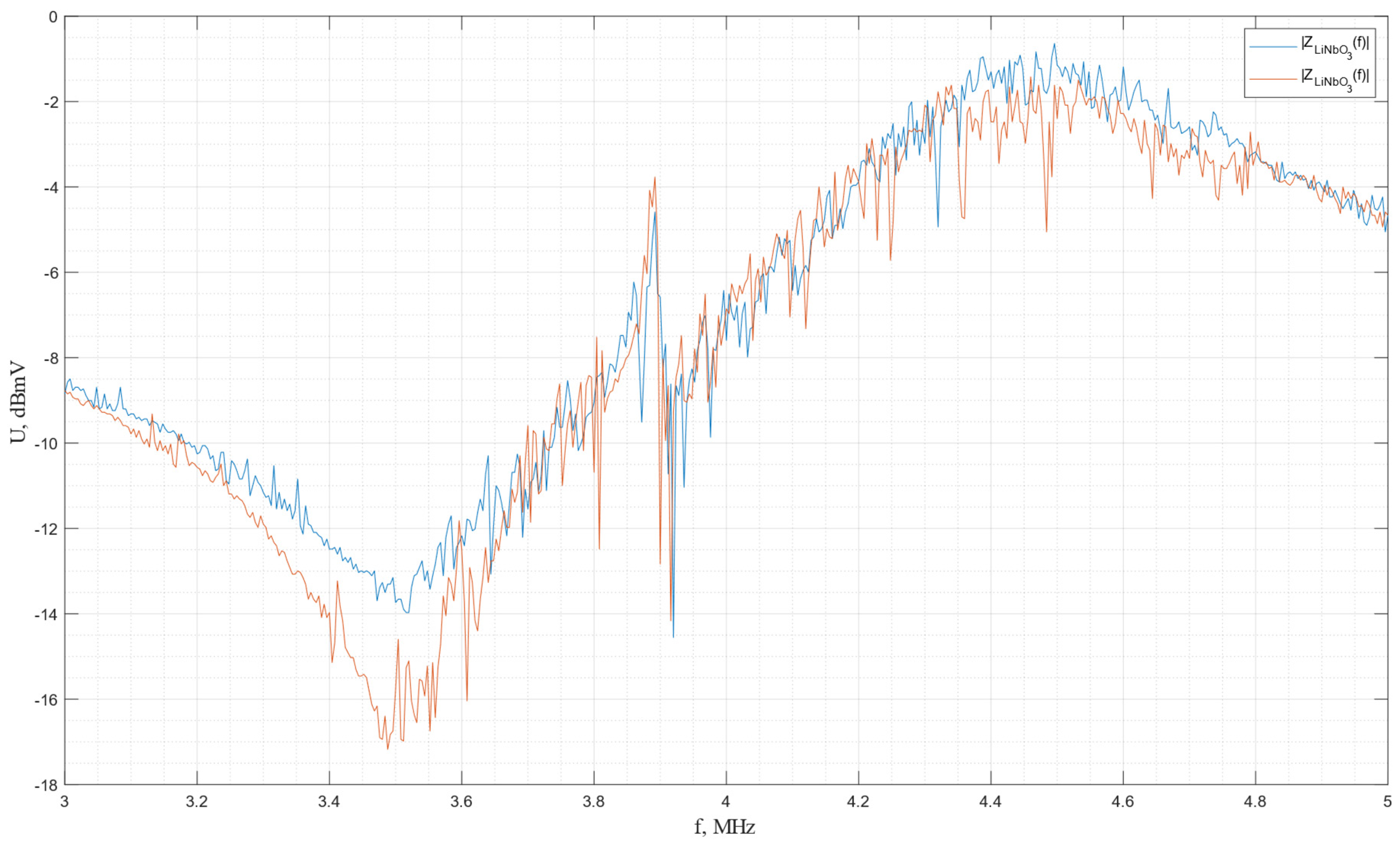
4.3. LiNbO3
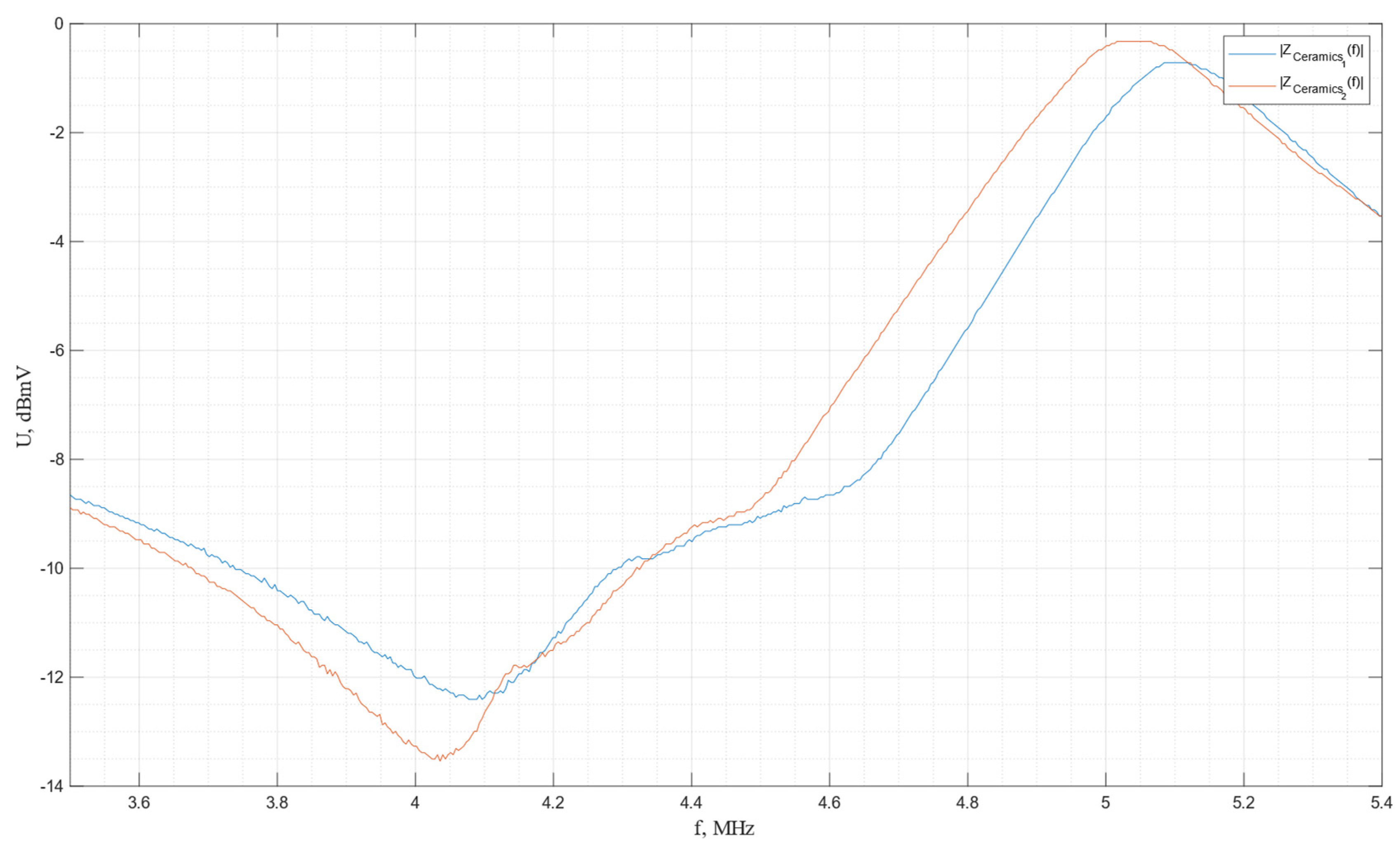
4.4. PZT-5H
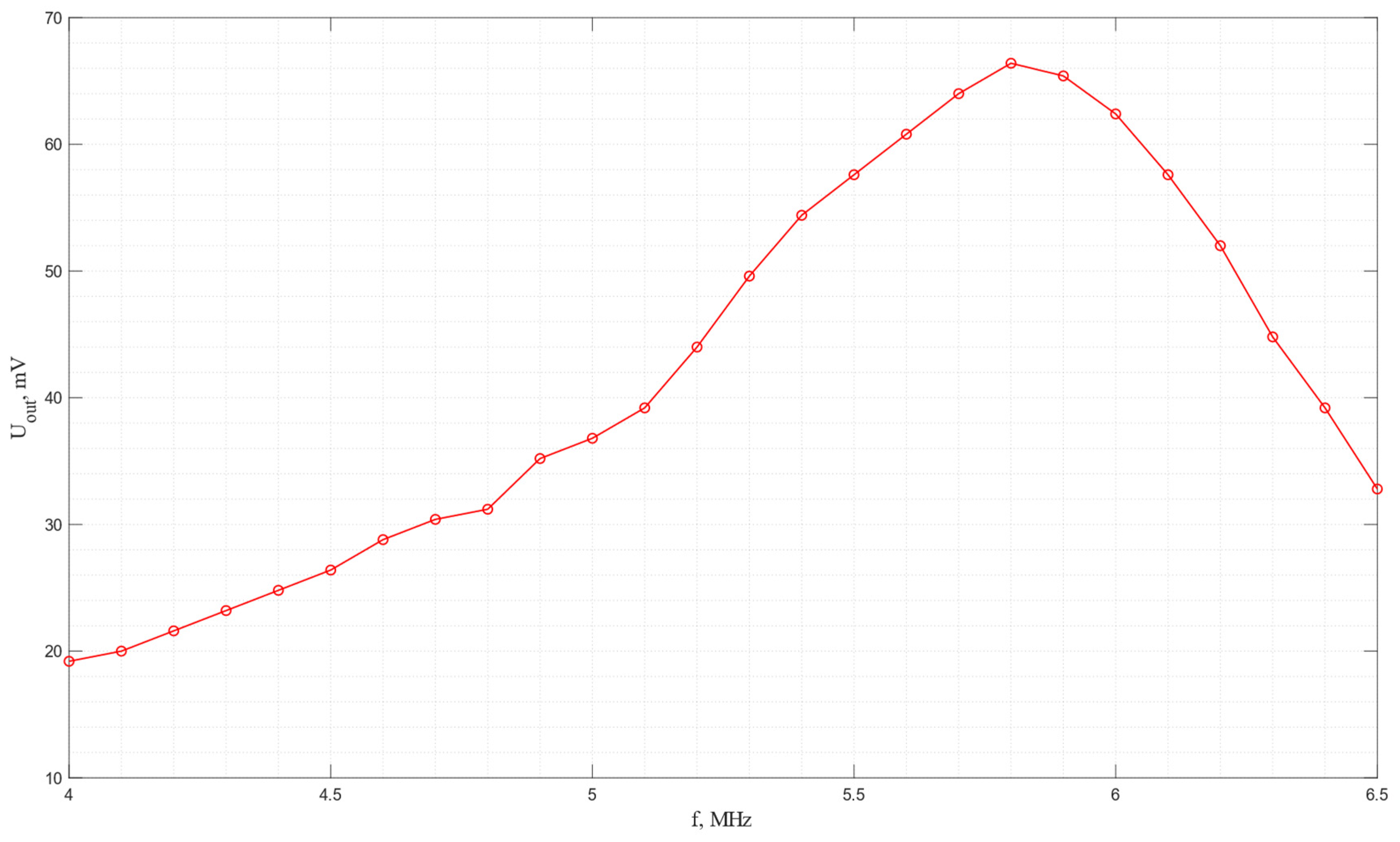
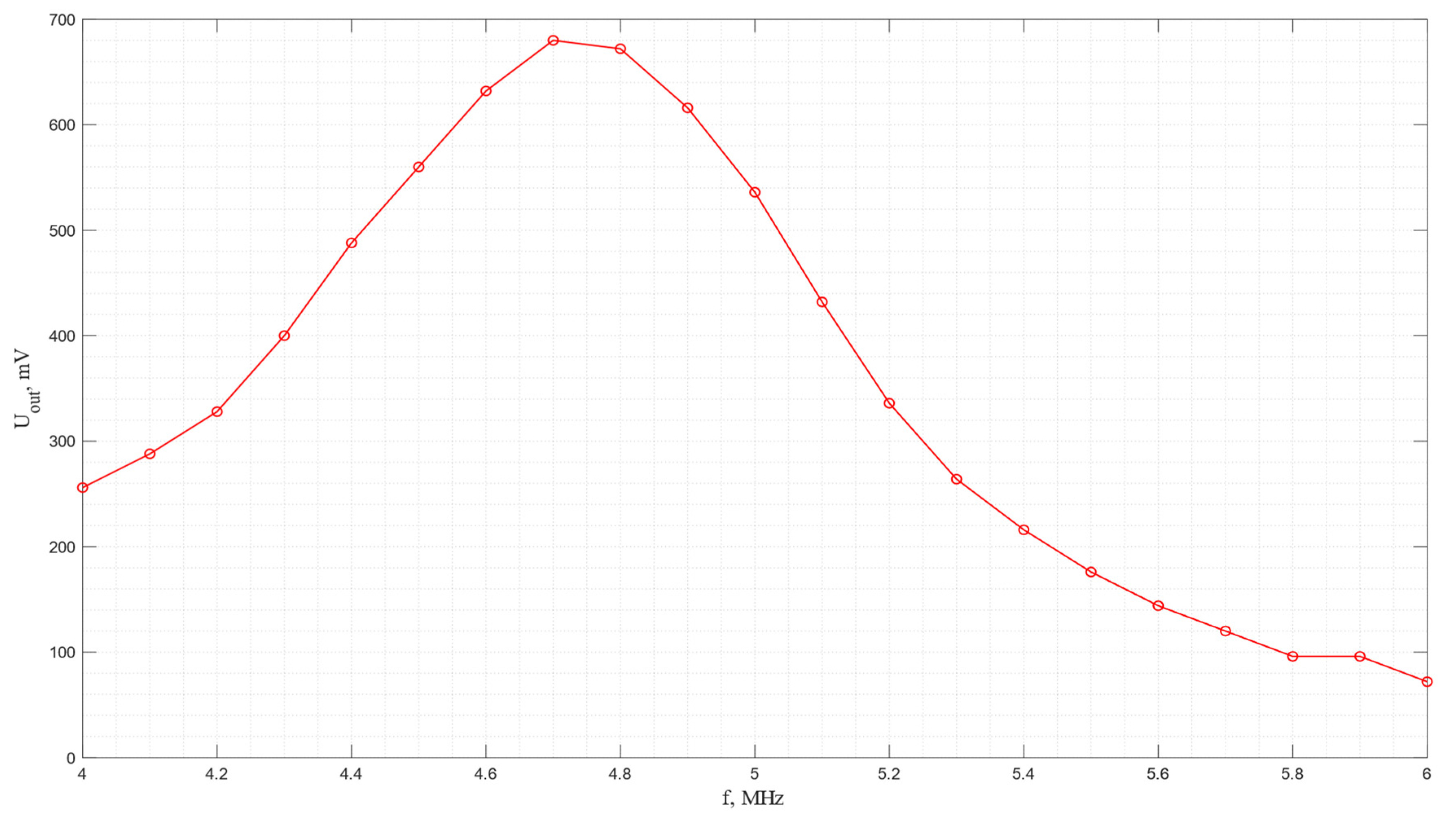
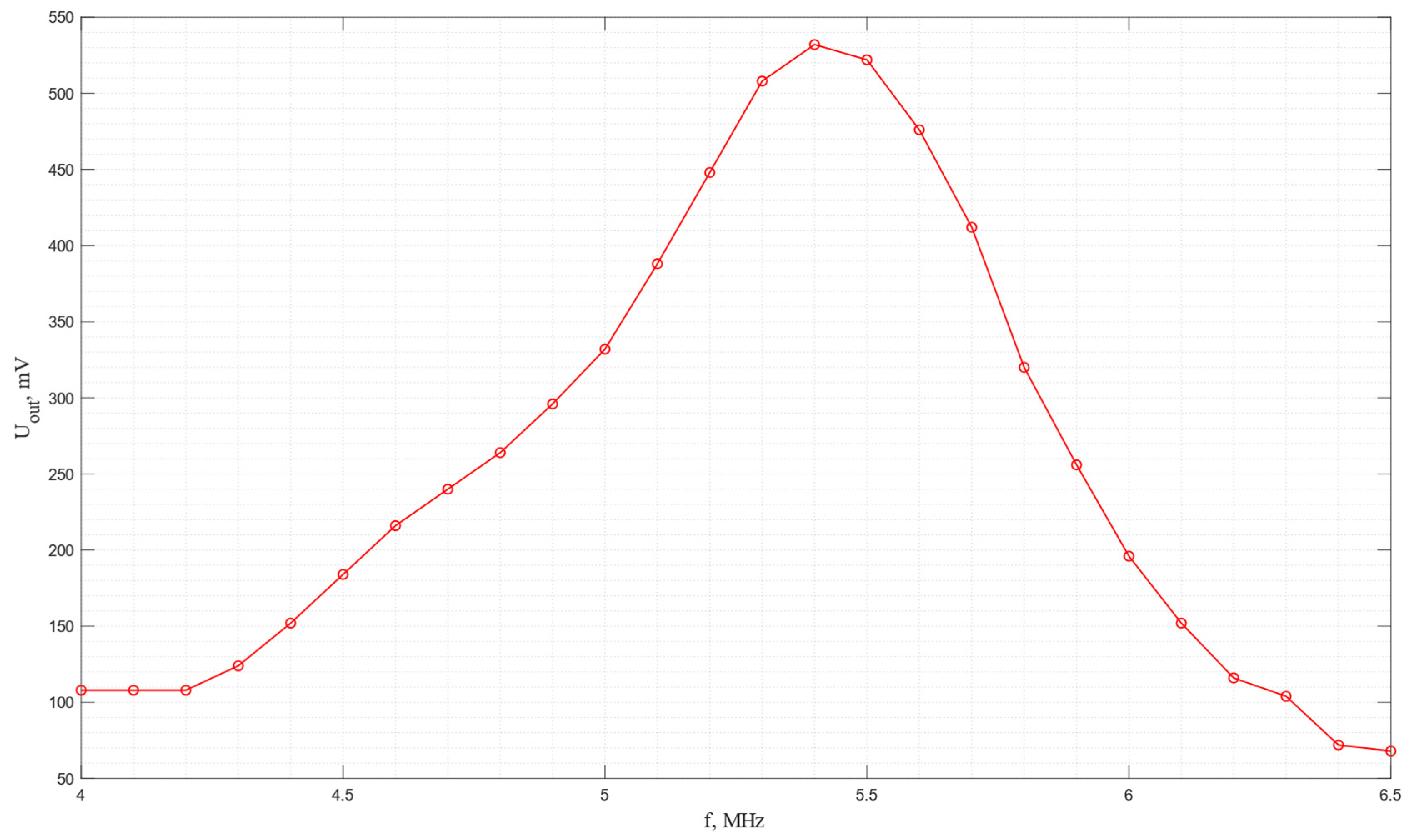
4.5. Frequency Characteristics of Piezodielectric Plates
5. Discussion
- When exploring the sensing potential of a new solid-state acoustic motion sensor on bulk acoustic waves, one of the critical tasks is to increase its sensitivity, as shown by the previous research [14,15,16]. Based on the results of theoretical analysis, the principle of increasing the sensing potential by improving the electroacoustic conversion efficiency of the piezoelectric plate transducers by selecting optimal materials and cuts was formulated in this research.
- The present paper provides the results of comprehensive theoretical, numerical, and experimental research studies conducted according to the formulated principles.
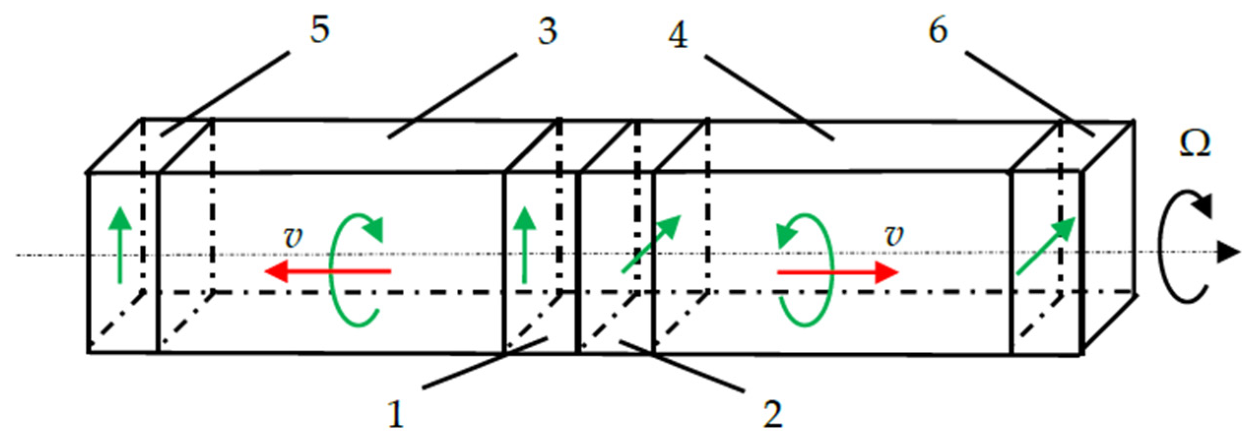
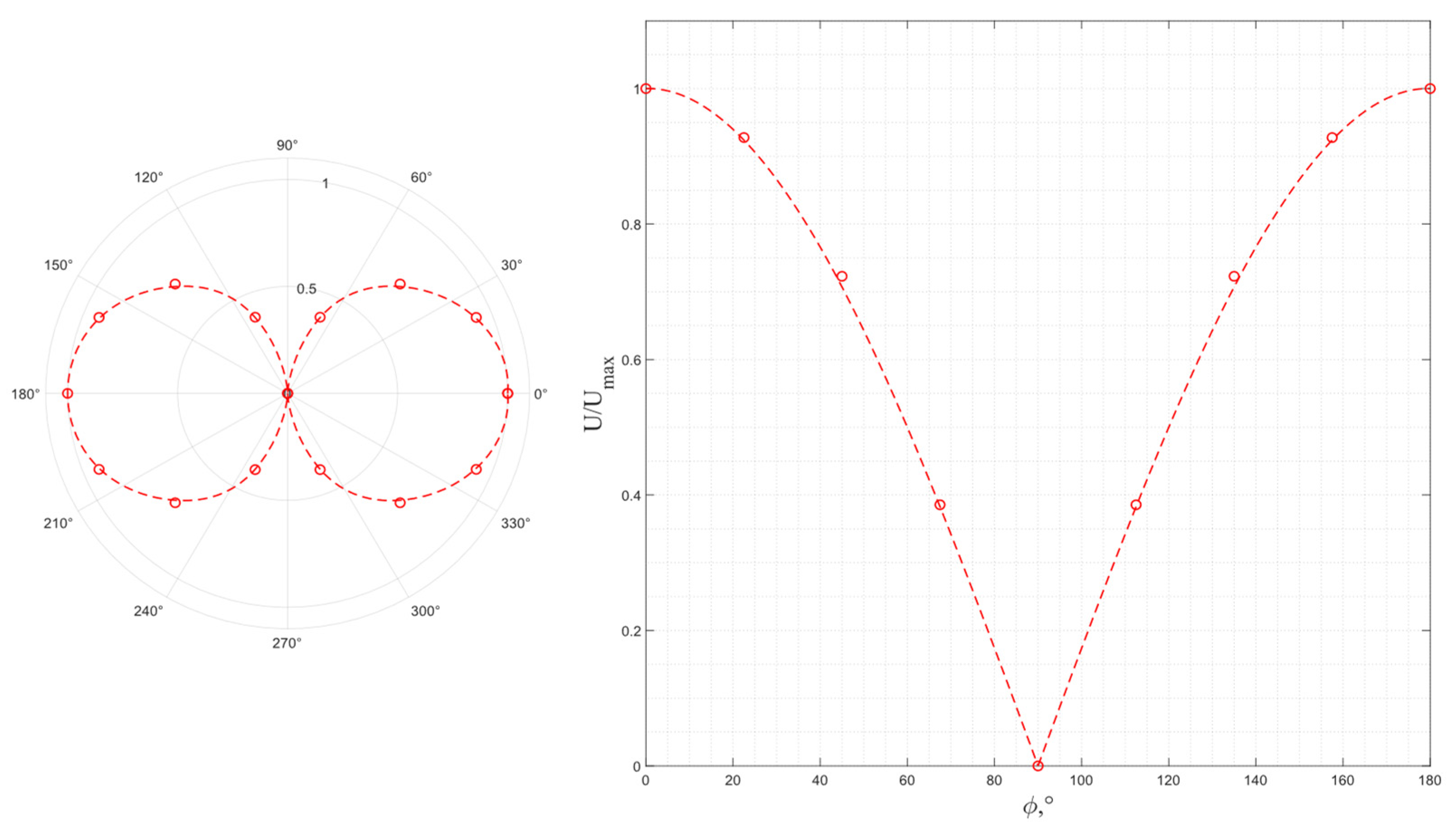
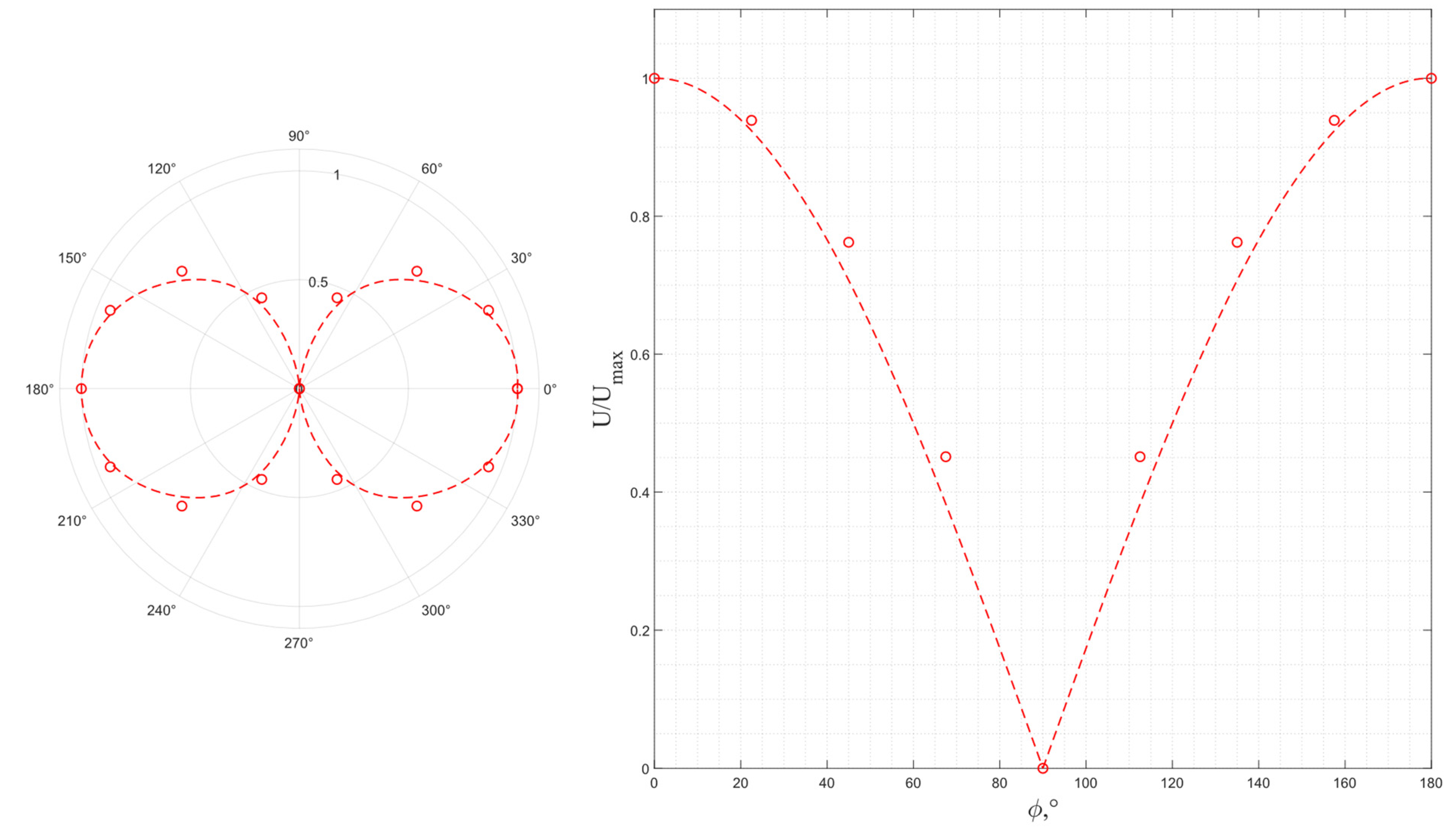
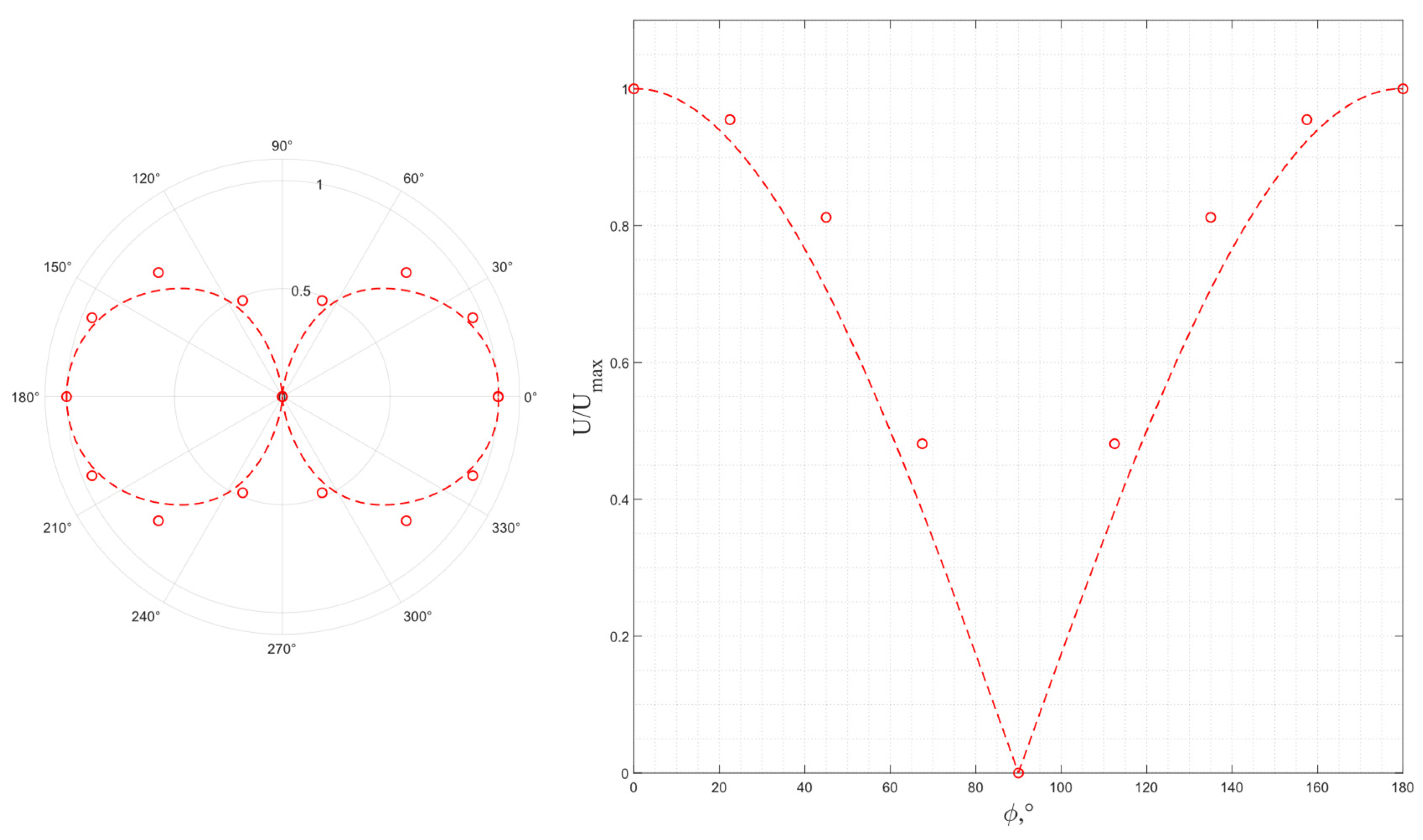
- The method of efficiency analysis was proposed by estimating the following parameters: the value of the acoustic wave propagation velocity, the coefficient of the electromechanical transformation, and the angle between the quasi-longitudinal wave polarization vector and its propagation direction. The last one is critically important to estimate to ensure the excitation of only one pure transverse wave, which is the required condition of new solid-state acoustic motion sensor operation.
- Numerical analysis was performed for the abovementioned parameters, and corresponding graphical dependencies were built for a number of materials and cuts: the Y cut of piezo quartz, Y cut of langasite, X cut of lithium niobate, and shear cut of PZT-5H. Taking into account the problem of calculation with relation to singularity points with a pair of eigenvalues equal to each other, a novel algorithm was developed that overcame an error in matching the phase velocity and polarization of the excited waves and subsequently ensured the operation of the piezoelectric plates and the sensor in general.
- Two series of experimental studies were carried out to confirm the numerical analysis results: the first one showed a high correlation with the numerical estimation of wave polarization and efficiency; the second one showed a high correlation with the numerical estimation of wave propagation velocities, thus validating the proposed method.
- Based on the results of theoretical analysis, numerical modeling, and experimental studies, Y-cut piezo quartz, Y-cut langasite, and shear cut ceramics were considered promising to be used as emitting and receiving piezo plates of novel bulk acoustic wave gyroscopes. However, piezo quartz has relatively low efficiency, piezoceramics are difficult to process in order to achieve high operating frequencies, and X-cut lithium niobate piezo plates are highly efficient but are not suitable due to the elliptical polarization of the emitted waves at any frequencies.
- Thus, Y-cut langasite is proposed as an optimal material to increase the sensing potential of the considered new solid-state acoustic motion sensors.
- The challenge for future scientific inquiry is to search for novel principles of constructive implementation and informative signal selection in order to increase sensing potential. One of the most promising directions is the solution of the problem of direct piezo plate radiation under rotation for the possible design simplification of the next generation of acoustic solid-state motion sensors on bulk acoustic waves.
Author Contributions
Funding
Data Availability Statement
Conflicts of Interest
References
- Ultrasonic Transducers; Nakamura, K. (Ed.) Woodhead Publishing: Cambridge, UK, 2012; 722p. [Google Scholar]
- Ultrasonic and Advanced Methods for Nondestructive Testing and Material Characterization; Chen, C.H. (Ed.) University of Massachusetts Dartmouth: North Dartmouth, MA, USA, 2007; 684p. [Google Scholar]
- Liu, X.; Chen, X.; Yang, Z.; Xia, H.; Zhang, C.; Wei, X. Surface acoustic wave based microfluidic devices for biological applications. Sens. Diagn. 2023, 2, 507–528. [Google Scholar] [CrossRef]
- Wu, Y.; Ma, Y.; Zheng, H.; Ramakrishna, S. Piezoelectric materials for flexible and wearable electronics: A review. Mater. Des. 2021, 211, 110164. [Google Scholar] [CrossRef]
- Garrett, D.C.; Wang, L.V. Acoustic sensing with light. Nat. Photonics 2021, 15, 324–326. [Google Scholar] [CrossRef]
- Zou, Y.; Gao, C.; Zhou, J.; Liu, Y.; Xu, Q.; Qu, Y.; Liu, W.; Soon, J.B.W.; Cai, Y.; Sun, C. Aluminum scandium nitride thin-film bulk acoustic resonators for 5G wideband applications. Microsyst. Nanoeng. 2022, 8, 124. [Google Scholar] [CrossRef] [PubMed]
- Kumar, A.; Prajesh, R. The potential of acoustic wave devices for gas sensing applications. Sens. Actuators A Phys. 2022, 339, 113498. [Google Scholar] [CrossRef]
- Sherrit, S.; Bao, X.; Bar-Cohen, Y.; Chang, Z. BAW and SAW sensors for in situ analysis. In Proceedings of the Smart Structures and Materials 2003: Smart Sensor Technology and Measurement Systems, San Diego, CA, USA, 2–6 March 2003; Volume 5050, pp. 81–91. [Google Scholar]
- Serhane, R.; Hadj-Larbi, F.; Lafane, S.; Abdelli-Messaci, S.; Boutkedjirt, T. The Heterostructure ZnO/Al/SiO2/Si Fabrication for Piezoelectric SAW and BAW Transducers and Sensors. J. New Technol. Mater. 2017, 277, 47–52. [Google Scholar] [CrossRef]
- Shevchenko, S.; Kukaev, A.; Khivrich, M.; Lukyanov, D. Surface-acoustic-wave sensor design for acceleration measurement. Sensors 2018, 18, 2301. [Google Scholar] [CrossRef] [PubMed]
- Subba Rao, V.; Nigam, S.D. Wave propagation in rotating elastic media. Mathematica 1964, 11, 29–38. [Google Scholar] [CrossRef]
- Schoenberg, M.; Censor, D. Elastic waves in rotating media. Quart. Appl. Math. 1973, 31, 115–125. [Google Scholar] [CrossRef]
- Schoenberg, M.; Censor, D. Two-dimensional wave problems in rotating elastic media. Appl. Sci. Res. 1973, 27, 401–414. [Google Scholar]
- Gribkova, E.; Kukaev, A.; Lukyanov, D.; Lutovinov, A.; Peregudov, A. Solid-state motion sensors on acoustic waves. Theory and experiment. In Proceedings of the 2014 Symposium on Piezoelectricity, Acoustic Waves, and Device Applications, Beijing, China, 30 October–2 November 2014; pp. 69–71. [Google Scholar]
- Durukan, Y.; Shevelko, M.; Peregudov, A.; Popkova, E.; Shevchenko, S. The effect of a rotating medium on bulk acoustic wave polarization: From theoretical considerations to perspective angular motion sensor design. Sensors 2020, 20, 2487. [Google Scholar] [CrossRef] [PubMed]
- Shevelko, M.; Lutovinov, A.; Peregudov, A.; Popkova, E.; Durukan, Y.; Shevchenko, S. The sensitive element of acoustic sensor on circular polarized waves: From theoretical consideration towards perspective rotation rate sensors design. Sensors 2021, 21, 32. [Google Scholar] [CrossRef] [PubMed]
- Fedorov, F.I. Theory of Elastic Waves in Crystals; Nauka: Moscow, Russia, 1965; 386p. [Google Scholar]
- Acoustic Crystals: Reference Book; Shaskolskaya, M.P. (Ed.) Nauka: Moscow, Russia, 1982; 632p. [Google Scholar]
- Available online: https://en.newpiezo.com/knowledge_base/ (accessed on 4 April 2024).
- Ogi, H.; Nakamura, N.; Sato, K.; Hirao, M.; Uda, S. Elastic, anelastic and piezoelectric coefficients of Langasite: Resonance ultrasound spectroscopy with laser-doppler interferometry. IEEE Trans. Ultrason. Ferroelectr. Freq. Control. 2003, 50, 553–560. [Google Scholar] [CrossRef]
- Balakirev, M.K.; Gilinsky, I.A. Waves in Piezocrystals; Nauka: Novosibirsk, USSR, 1982; 240p. [Google Scholar]


| Material | d, mm | fa, MHz | vexp, mm/μs | vcalc, mm/μs | Δv, % |
|---|---|---|---|---|---|
| Piezo quartz | 0.38 | 5.126 | 3.896 | 3.915 | 0.5 |
| 0.38 | 5.125 | 3.895 | 3.915 | 0.5 | |
| La3Ga5SiO14 | 0.28 | 4.877 | 2.731 | 2.741 | 0.4 |
| 0.28 | 4.874 | 2.729 | 2.741 | 0.4 | |
| LiNbO3 | 0.52 | 3.892 | 4.048 | 4.058 | 0.2 |
| 4.496 | 4.676 | 4.806 | 3.0 | ||
| 0.52 | 3.916 | 4.072 | 4.058 | 0.3 | |
| 4.460 | 4.638 | 4.806 | 3.0 | ||
| PZT-5H | 0.22 | 5.103 | 2.245 | 2.372 | 5.0 |
| 0.22 | 5.039 | 2.217 | 2.372 | 6.0 |
Disclaimer/Publisher’s Note: The statements, opinions and data contained in all publications are solely those of the individual author(s) and contributor(s) and not of MDPI and/or the editor(s). MDPI and/or the editor(s) disclaim responsibility for any injury to people or property resulting from any ideas, methods, instructions or products referred to in the content. |
© 2024 by the authors. Licensee MDPI, Basel, Switzerland. This article is an open access article distributed under the terms and conditions of the Creative Commons Attribution (CC BY) license (https://creativecommons.org/licenses/by/4.0/).
Share and Cite
Shevelko, M.; Baranov, A.; Popkova, E.; Staroverova, Y.; Peregudov, A.; Kukaev, A.; Shevchenko, S. New Solid-State Acoustic Motion Sensors: Sensing Potential Estimation for Different Piezo Plate Materials. Sensors 2024, 24, 4271. https://doi.org/10.3390/s24134271
Shevelko M, Baranov A, Popkova E, Staroverova Y, Peregudov A, Kukaev A, Shevchenko S. New Solid-State Acoustic Motion Sensors: Sensing Potential Estimation for Different Piezo Plate Materials. Sensors. 2024; 24(13):4271. https://doi.org/10.3390/s24134271
Chicago/Turabian StyleShevelko, Michail, Andrey Baranov, Ekaterina Popkova, Yasemin Staroverova, Aleksandr Peregudov, Alexander Kukaev, and Sergey Shevchenko. 2024. "New Solid-State Acoustic Motion Sensors: Sensing Potential Estimation for Different Piezo Plate Materials" Sensors 24, no. 13: 4271. https://doi.org/10.3390/s24134271