
Sensor-Enhanced Smart Gripper Development for Automated Meat Processing

 ,
,  , ,
, ,  and
and 
Abstract
:1. Introduction
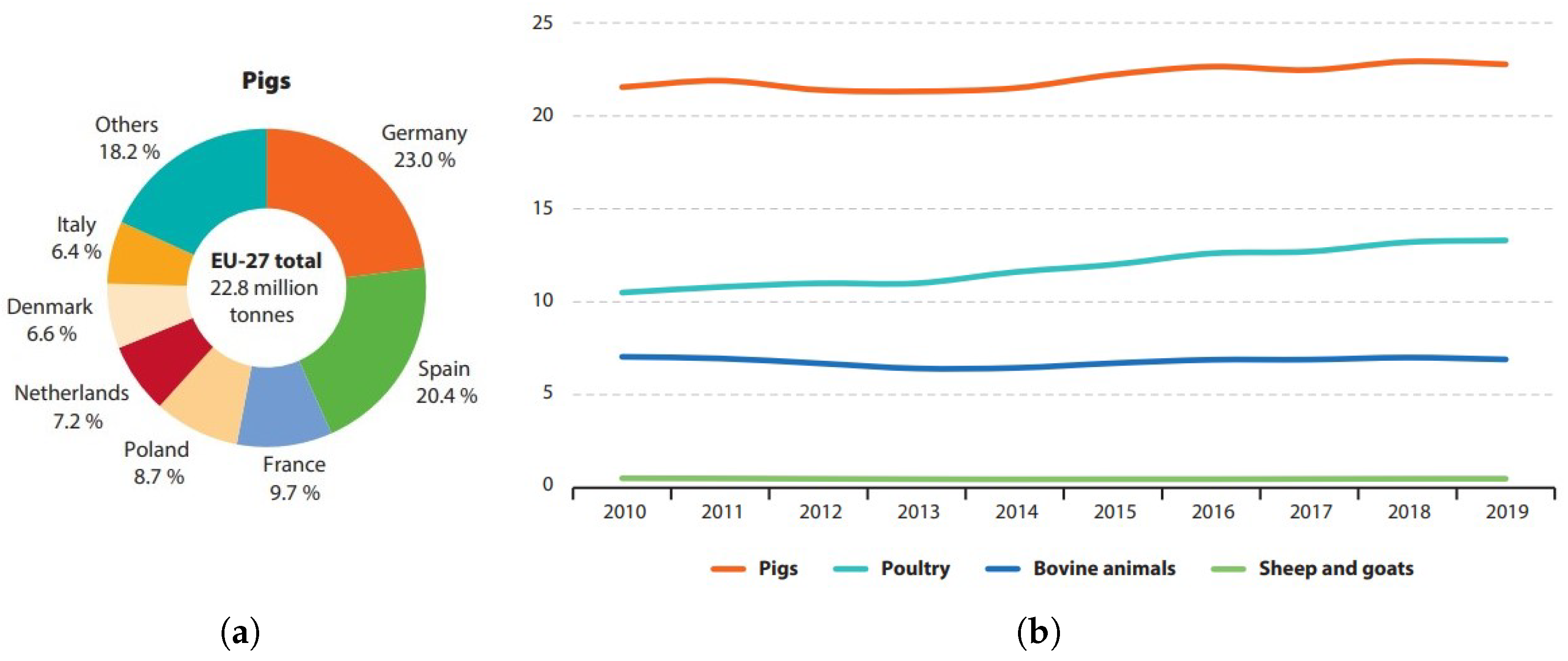
1.1. Background
1.2. Meat Industry Grippers
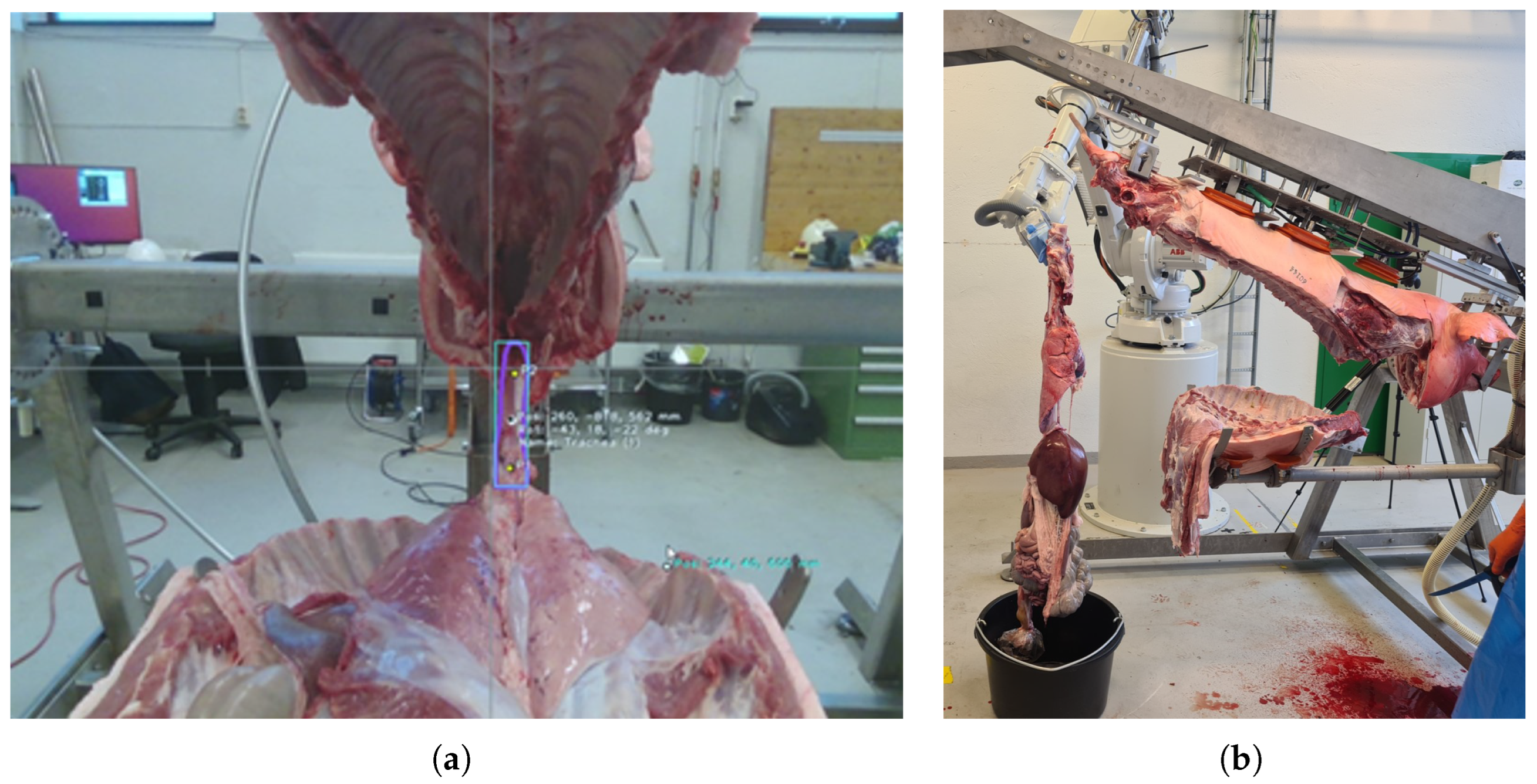
1.3. The RoBUTCHER Project
2. Materials and Methods
- Encircling gripping motion for target displacement tolerance;
- Cleanability, disinfectability, i.e., waterproof design;
- High payload (up to 30 kg);
- Fail-safe operation on power cut;
- Smart functionalities:
- -
- Force-controlled gripping;
- -
- Slip detection;
- -
- Wireless communication (for development and analysis);
- -
- Real-time feedback about successful grasping;
- -
- Real-time feedback about target displacement.
2.1. Requirements
- Reliable grasping of a cylindrical object with known position and orientation in space:
- -
- Diameter: 3–4 cm;
- -
- Might be a random mass of soft tissues, up to 6–8 cm across;
- -
- Slippery, wet surface;
- -
- Relatively high position and orientation error should be hypothesized;
- All parts of the gripper should withstand at least 400 N (tensile strength of the trachea);
- Made of food-grade materials;
- Easy-to-clean design; can be decontaminated with industrial methods;
- Can be applied onto an industrial manipulator robot as an end-effector (both mechanically and electronically);
- Smart functionalities:
- -
- Closing-force sensing and/or control;
- -
- Slip-detection;
- -
- Feedback to the robot cell regarding the grasping.
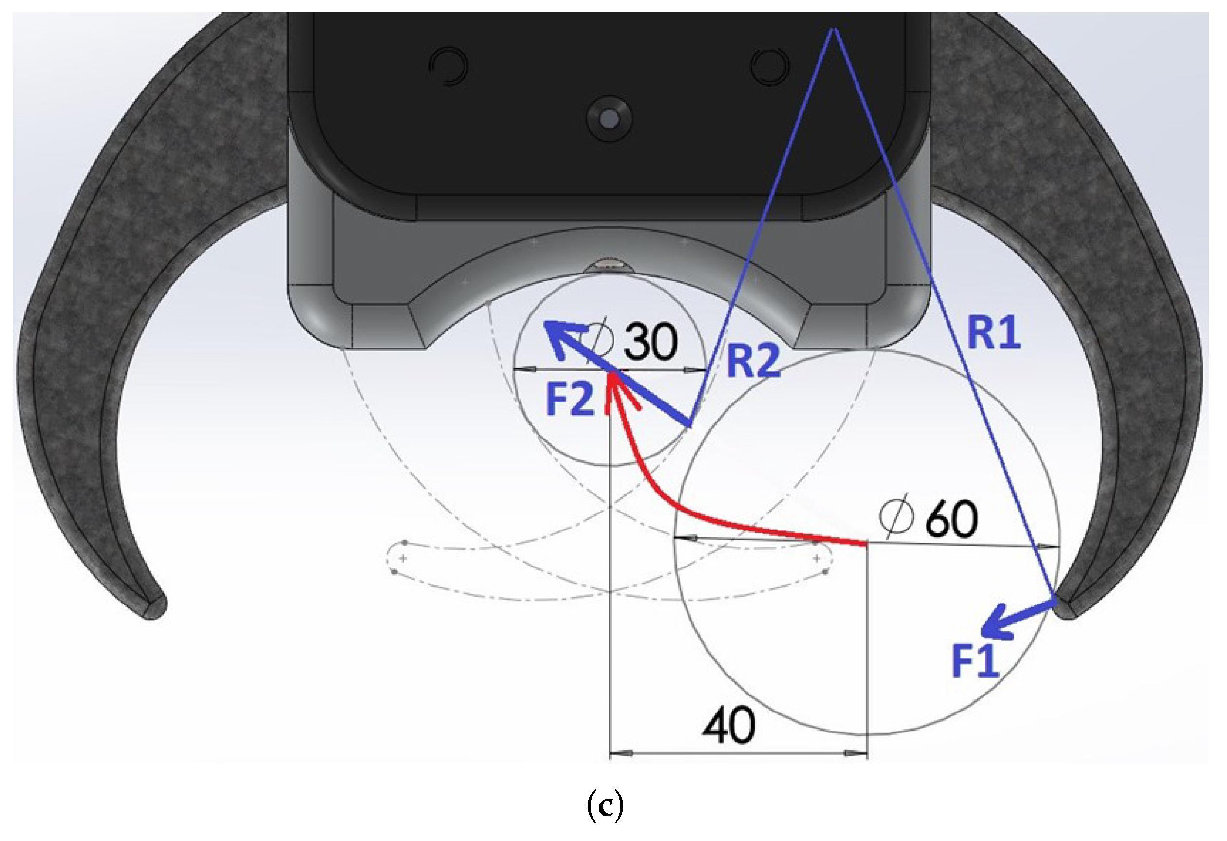
2.2. Mechanical Design
- The fingers can reach around, lock on and pull in the target object within a sufficient diameter-range;
- The encircling motion allows compensation for uncertainty in the gripper-positioning (displacement of the leg/trachea in a radial direction and angular error);
- The design is modular, the shape of the fingers can be optimized for future tasks as well, as they are easily replaced;
- Gripping force can be measured and controlled relatively easily compared to soft grippers.
2.3. Final Gripper Design
- Elongated shape and an additional spacer for robot workspace optimization;
- Completely sealed design;
- Optimized finger-shape;
- Stronger motor;
- All electronic components are soldered on dedicated, manufactured PCBs;
- Different novel integrated gripping force sensing solutions implemented;
- Smart features implemented: slip detection, force control, 2-way communication with the robot cell.
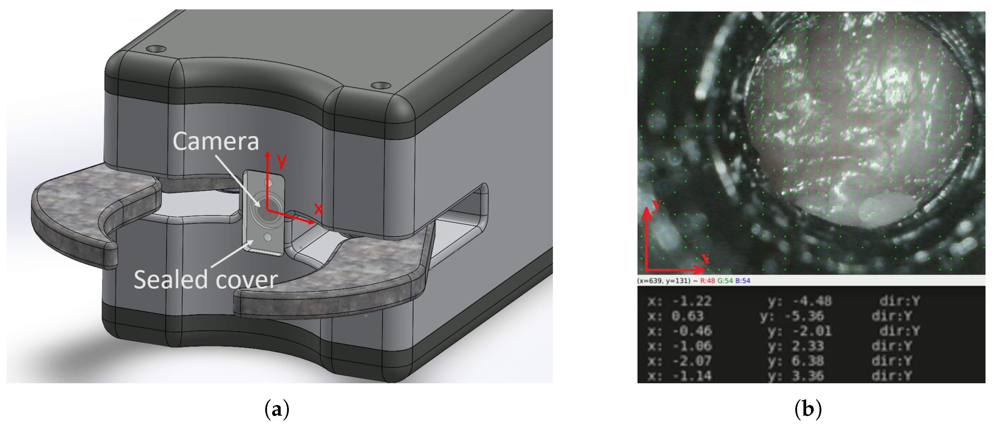
2.4. Smart Features
2.4.1. Force-Controlled Gripping
2.4.2. Slip Detection
3. Results
3.1. Mechanical Design
3.2. Smart Features
4. Discussion
5. Conclusions
Author Contributions
Funding
Institutional Review Board Statement
Data Availability Statement
Conflicts of Interest
Abbreviations
| AI | Artificial Intelligence |
| CAD | Computer-Aided Design |
| CHU | Carcass Handling Unit |
| DMRI | Danish Technological Institute |
| DOF | Degrees of Freedom |
| EOAT | End of Arm Tooling |
| EU | European Union |
| FPS | Frames per Second |
| GPIO | General Purpose Input/Output |
| MFC | Meat Factory Cell |
| NMBU | Norwegian University of Life Sciences |
| PCB | Printed Circuit Board |
| ROI | Region of Interest |
| RGB-D camera | Red-Green-Blue-Depth camera |
References
- European Commission; Eurostat. Agriculture, Forestry and Fishery Statistics: 2020 Edition; Publications Office of the European Union: Luxembourg, 2021. [Google Scholar] [CrossRef]
- Delmore, R.J. Automation in the global meat industry. Anim. Front. 2022, 12, 3–4. [Google Scholar] [CrossRef]
- Szabo, S.; Alexy, M. Practical Aspects of Weight Measurement Using Image Processing Methods in Waterfowl Production. Agriculture 2022, 12, 1869. [Google Scholar] [CrossRef]
- Orosz, G.; Szabó, R.Z.; Ungi, T.; Barr, C.; Yeung, C.; Fichtinger, G.; Gál, J.; Haidegger, T. Lung Ultrasound Imaging and Image Processing with Artificial Intelligence Methods for Bedside Diagnostic Examinations. Acta Polytech. Hung. 2023, 20, 69–87. [Google Scholar] [CrossRef]
- Lukács, E.; Levendovics, R.; Haidegger, T. Enhancing Autonomous Skill Assessment of Robot-Assisted Minimally Invasive Surgery: A Comprehensive Analysis of Global and Gesture-Level Techniques applied on the JIGSAWS Dataset. Acta Polytech. Hung. 2023, 20, 133–153. [Google Scholar] [CrossRef]
- Fichtinger, G.; Troccaz, J.; Haidegger, T. Image-guided interventional robotics: Lost in translation? Proc. IEEE 2022, 110, 932–950. [Google Scholar] [CrossRef]
- Haidegger, T.; Speidel, S.; Stoyanov, D.; Satava, R.M. Robot-assisted minimally invasive surgery—Surgical robotics in the data age. Proc. IEEE 2022, 110, 835–846. [Google Scholar] [CrossRef]
- Tai, K.; El-Sayed, A.R.; Shahriari, M.; Biglarbegian, M.; Mahmud, S. State of the Art Robotic Grippers and Applications. Robotics 2016, 5, 11. [Google Scholar] [CrossRef]
- Takács, K.; Mason, A.; Cordova-Lopez, L.E.; Alexy, M.; Galambos, P.; Haidegger, T. Current Safety Legislation of Food Processing Smart Robot Systems–The Red Meat Sector. Acta Polytech. Hung. 2022, 19, 249–267. [Google Scholar] [CrossRef]
- Ross, S.; Korostynska, O.; Cordova-Lopez, L.; Mason, A. A review of unilateral grippers for meat industry automation. Trends Food Sci. Technol. 2022, 119, 309–319. [Google Scholar] [CrossRef]
- Zhou, X.; Majidi, C.; O’Reilly, O.M. Soft hands: An analysis of some gripping mechanisms in soft robot design. Int. J. Solids Struct. 2015, 64, 155–165. [Google Scholar] [CrossRef]
- Shintake, J.; Cacucciolo, V.; Floreano, D.; Shea, H. Soft robotic grippers. Adv. Mater. 2018, 30, 1707035. [Google Scholar] [CrossRef] [PubMed]
- Glick, P.; Suresh, S.A.; Ruffatto, D.; Cutkosky, M.; Tolley, M.T.; Parness, A. A soft robotic gripper with gecko-inspired adhesive. IEEE Robot. Autom. Lett. 2018, 3, 903–910. [Google Scholar] [CrossRef]
- Tian, H.; Liu, H.; Shao, J.; Li, S.; Li, X.; Chen, X. An electrically active gecko-effect soft gripper under a low voltage by mimicking gecko’s adhesive structures and toe muscles. Soft Matter 2020, 16, 5599–5608. [Google Scholar] [CrossRef] [PubMed]
- Cauligi, A.; Chen, T.G.; Suresh, S.A.; Dille, M.; Ruiz, R.G.; Vargas, A.M.; Pavone, M.; Cutkosky, M. Design and development of a gecko-adhesive gripper for the Astrobee free-flying robot. arXiv 2020, arXiv:2009.09151. [Google Scholar]
- Luo, A.; Pande, S.S.; Turner, K.T. Versatile Adhesion-Based Gripping via an Unstructured Variable Stiffness Membrane. Soft Robotics 2022, 9, 1177–1185. [Google Scholar] [CrossRef] [PubMed]
- Guo, J.; Leng, J.; Rossiter, J. Electroadhesion technologies for robotics: A comprehensive review. IEEE Trans. Robot. 2019, 36, 313–327. [Google Scholar] [CrossRef]
- Petterson, A.; Ohlsson, T.; Caldwell, D.G.; Davis, S.; Gray, J.O.; Dodd, T.J. A Bernoulli principle gripper for handling of planar and 3D (food) products. Ind. Robot. Int. J. 2010, 37, 518–526. [Google Scholar] [CrossRef]
- Li, X.; Li, N.; Tao, G.; Liu, H.; Kagawa, T. Experimental comparison of Bernoulli gripper and vortex gripper. Int. J. Precis. Eng. Manuf. 2015, 16, 2081–2090. [Google Scholar] [CrossRef]
- van den Berg, J. Capillary-Based Gripping for Laparoscopic Bowel Surgery. Master’s Thesis, Technische Universiteit Delft, Delft, The Netherlands, 2018. [Google Scholar]
- Natarajan, E.; Hong, L.W.; Ramasamy, M.; Hou, C.C.; Sengottuvelu, R. Design and development of a robot gripper for food industries using coanda effect. In Proceedings of the 2018 IEEE 4th International Symposium in Robotics and Manufacturing Automation (ROMA), Perambalur, India, 10–12 December 2018; IEEE: Piscataway, NJ, USA, 2018; pp. 1–5. [Google Scholar]
- Jørgensen, T.B.; Jensen, S.H.N.; Aanæs, H.; Hansen, N.W.; Krüger, N. An adaptive robotic system for doing pick and place operations with deformable objects. J. Intell. Robot. Syst. 2019, 94, 81–100. [Google Scholar] [CrossRef]
- Franke, K.; Hukelmann, B. Hygiene and functionality united: Vacuum grippers for automated handling of meat and meat products. Fleischwirtsch. Int. J. Meat Prod. Meat Process. 2011, 90, 60–61. [Google Scholar]
- Alvseike, O.; Prieto, M.; Torkveen, K.; Ruud, C.; Nesbakken, T. Meat inspection and hygiene in a Meat Factory Cell–An alternative concept. Food Control 2018, 90, 32–39. [Google Scholar] [CrossRef]
- Mason, A.; de Medeiros Esper, I.; Korostynska, O.; Cordova-Lopez, L.E.; Romanov, D.; Pinceková, M.; Bjørnstad, P.H.; Alvseike, O.; Popov, A.; Smolkin, O.; et al. RoBUTCHER: A novel robotic meat factory cell platform. Int. J. Robot. Res. 2024. [Google Scholar] [CrossRef]
- Alvseike, O.; Prieto, M.; Bjørnstad, P.H.; Mason, A. Intact gastro-intestinal tract removal from pig carcasses in a novel Meat Factory Cell approach. Acta Vet. Scand. 2020, 62, 47. [Google Scholar] [CrossRef] [PubMed]
- de Medeiros Esper, I.; From, P.J.; Mason, A. Robotisation and intelligent systems in abattoirs. Trends Food Sci. Technol. 2021, 108, 214–222. [Google Scholar] [CrossRef]
- Haidegger, T.P.; Galambos, P.; Tar, J.K.; Kovács, L.A.; Kozlovszky, M.; Zrubka, Z.; Eigner, G.; Drexler, D.A.; Szakál, A.; Reicher, V.; et al. Strategies and Outcomes of Building a Successful University Research and Innovation Ecosystem. Acta Polytechnica Hungarica 2024, 21, 10. [Google Scholar] [CrossRef]
- Károly, A.I.; Elek, R.N.; Haidegger, T.; Széll, K.; Galambos, P. Optical flow-based segmentation of moving objects for mobile robot navigation using pre-trained deep learning models. In Proceedings of the 2019 IEEE International Conference on Systems, Man and Cybernetics (SMC), Bari, Italy, 6–9 October 2019; pp. 3080–3086. [Google Scholar]
- Farnebäck, G. Two-frame motion estimation based on polynomial expansion. In Proceedings of the Scandinavian Conference on Image Analysis, Halmstad, Sweden, 29 June–2 July 2003; pp. 363–370. [Google Scholar]
- Haidegger, T.; Mai, V.; Mörch, C.; Boesl, D.; Jacobs, A.; Rao R, B.; Khamis, A.; Lach, L.; Vanderborght, B. Robotics: Enabler and inhibitor of the sustainable development goals. Sustain. Prod. Consum. 2023, 43, 422–434. [Google Scholar] [CrossRef]
- Alex, M.; Tamas, H.; Ole, A. Time for change: The case of robotic food processing. IEEE Robot. Autom. Mag. 2023, 30, 116–122. [Google Scholar]


Disclaimer/Publisher’s Note: The statements, opinions and data contained in all publications are solely those of the individual author(s) and contributor(s) and not of MDPI and/or the editor(s). MDPI and/or the editor(s) disclaim responsibility for any injury to people or property resulting from any ideas, methods, instructions or products referred to in the content. |
© 2024 by the authors. Licensee MDPI, Basel, Switzerland. This article is an open access article distributed under the terms and conditions of the Creative Commons Attribution (CC BY) license (https://creativecommons.org/licenses/by/4.0/).
Share and Cite
Takács, K.; Takács, B.; Garamvölgyi, T.; Tarsoly, S.; Alexy, M.; Móga, K.; Rudas, I.J.; Galambos, P.; Haidegger, T. Sensor-Enhanced Smart Gripper Development for Automated Meat Processing. Sensors 2024, 24, 4631. https://doi.org/10.3390/s24144631
Takács K, Takács B, Garamvölgyi T, Tarsoly S, Alexy M, Móga K, Rudas IJ, Galambos P, Haidegger T. Sensor-Enhanced Smart Gripper Development for Automated Meat Processing. Sensors. 2024; 24(14):4631. https://doi.org/10.3390/s24144631
Chicago/Turabian StyleTakács, Kristóf, Bence Takács, Tivadar Garamvölgyi, Sándor Tarsoly, Márta Alexy, Kristóf Móga, Imre J. Rudas, Péter Galambos, and Tamás Haidegger. 2024. "Sensor-Enhanced Smart Gripper Development for Automated Meat Processing" Sensors 24, no. 14: 4631. https://doi.org/10.3390/s24144631