

Autonomous Crack Detection for Mountainous Roads Using UAV Inspection System
 ,
,
Abstract
:1. Introduction
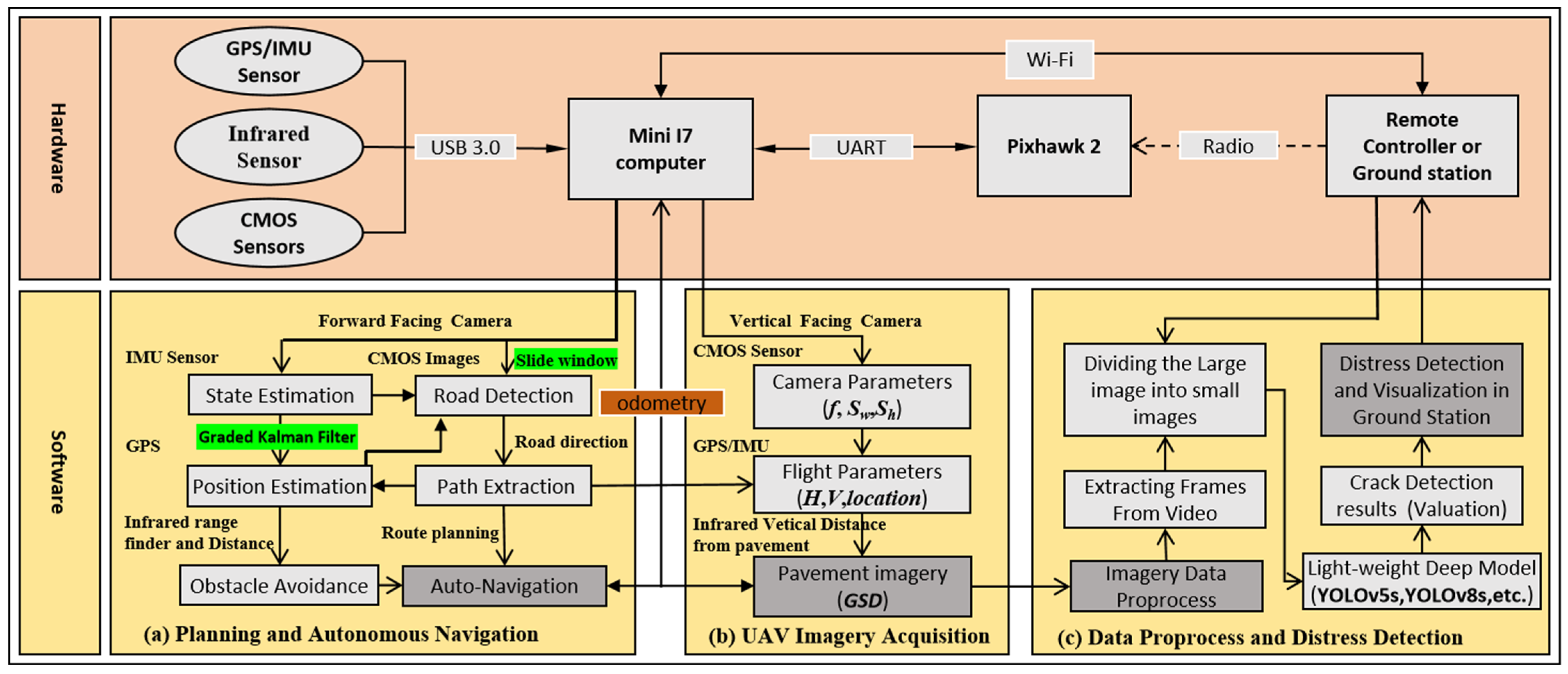
2. Architecture of the UAV Autonomous Inspection System
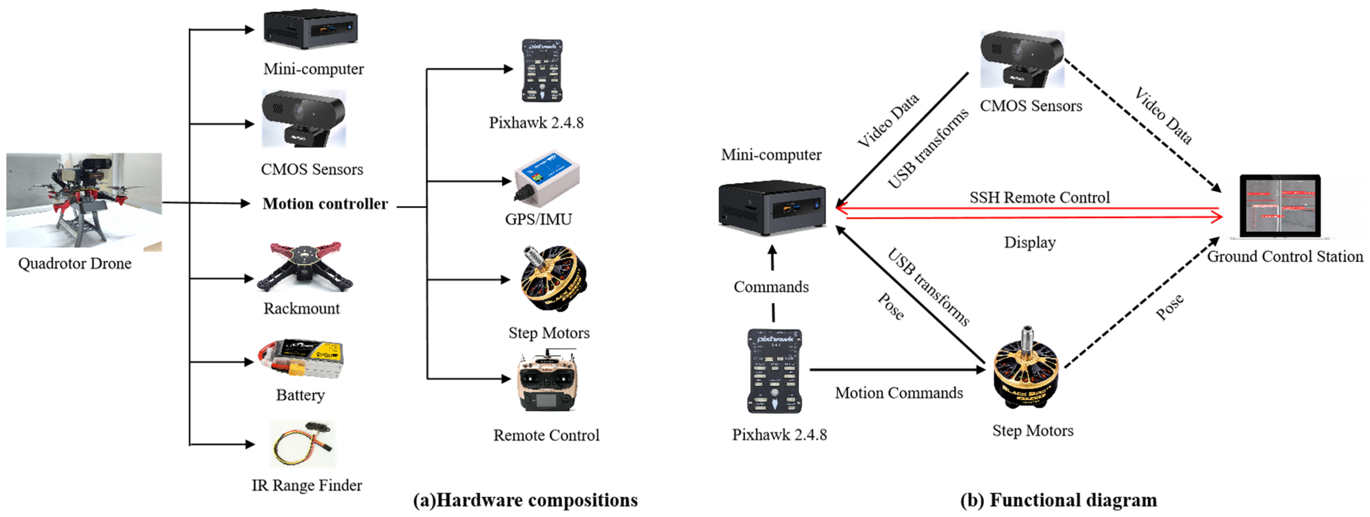
2.1. Hardware System
2.2. Software Systems
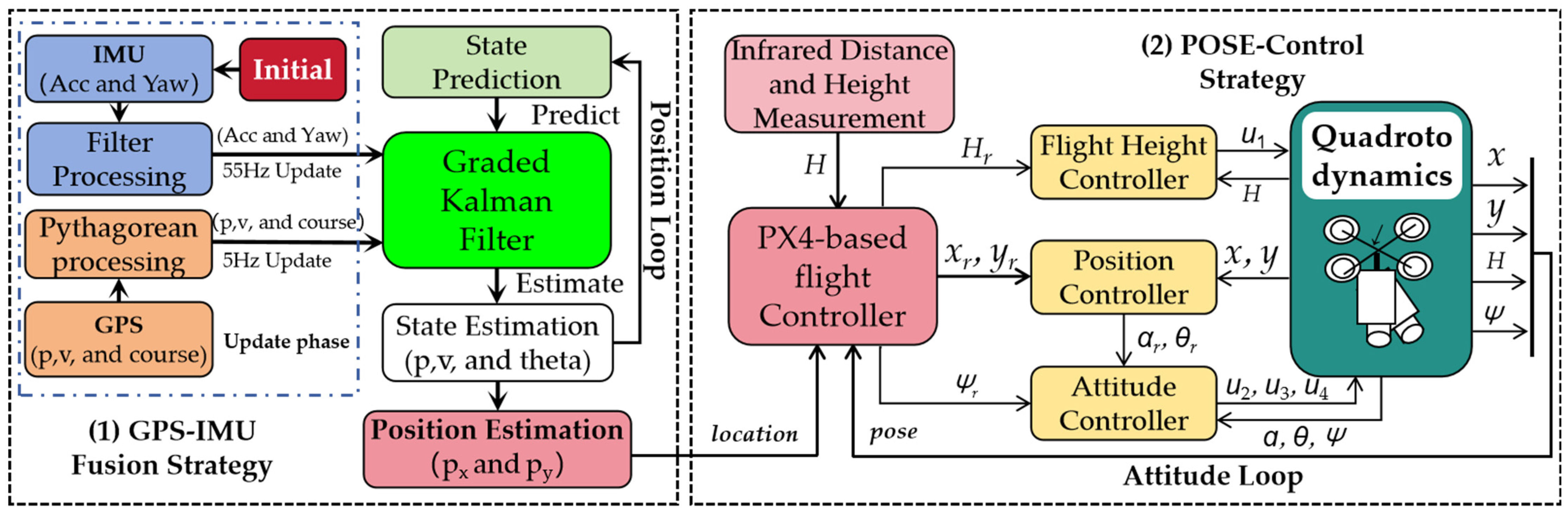
2.2.1. Planning and Autonomous Navigation
- (1)
- Flight Controller and Auto Vertical Height
- (2)
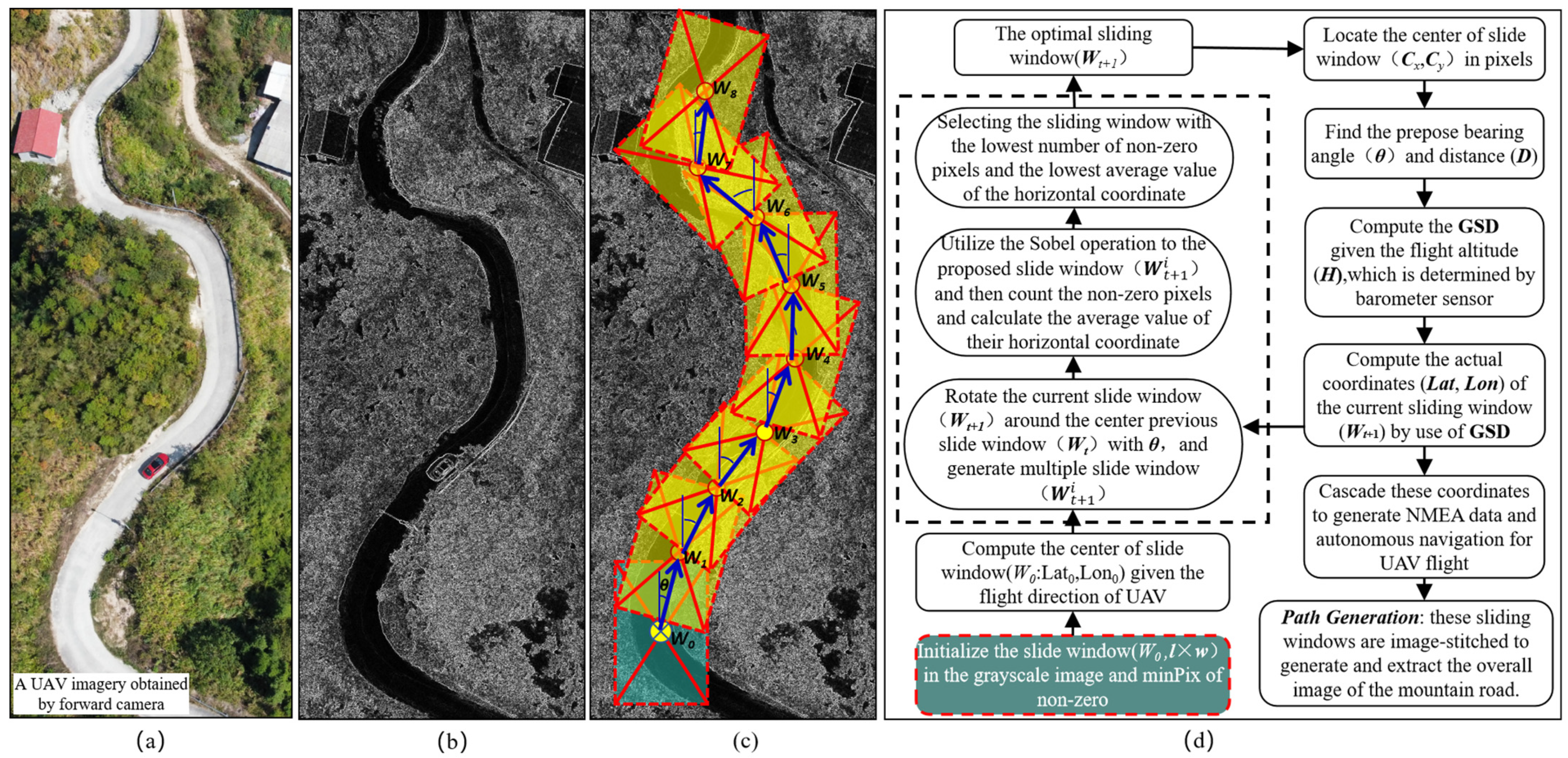
- Path Extraction and Autonomous Navigation
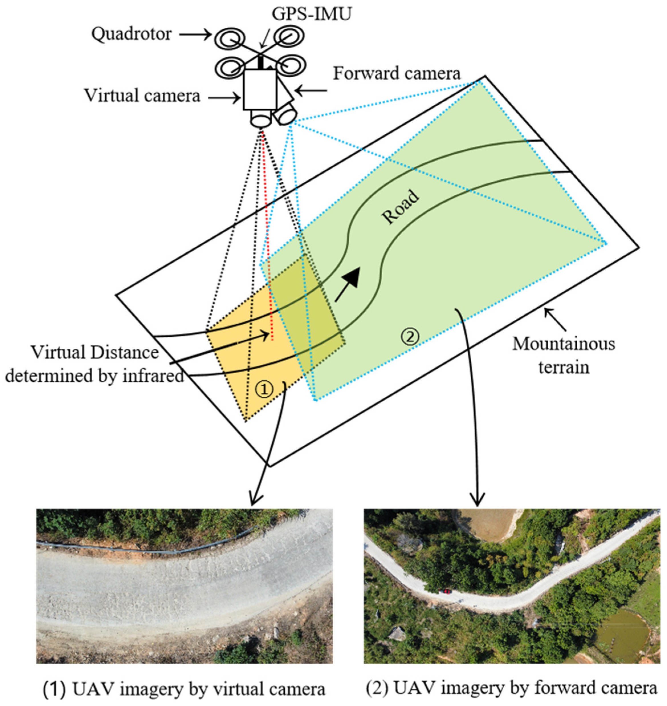
2.2.2. UAV Data Acquisition for Mountainous Roads
3. Pavement Autonomous Crack Detection with Improved YOLOv8
3.1. Dataset Collection and Labeling
3.2. Detection Method Based on the Enhanced YOLOv8 Model
3.2.1. EIOU Function
3.2.2. DWR Segmentation
3.3. Training Process of the Improved YOLOv8 Model
4. Experiments and Results
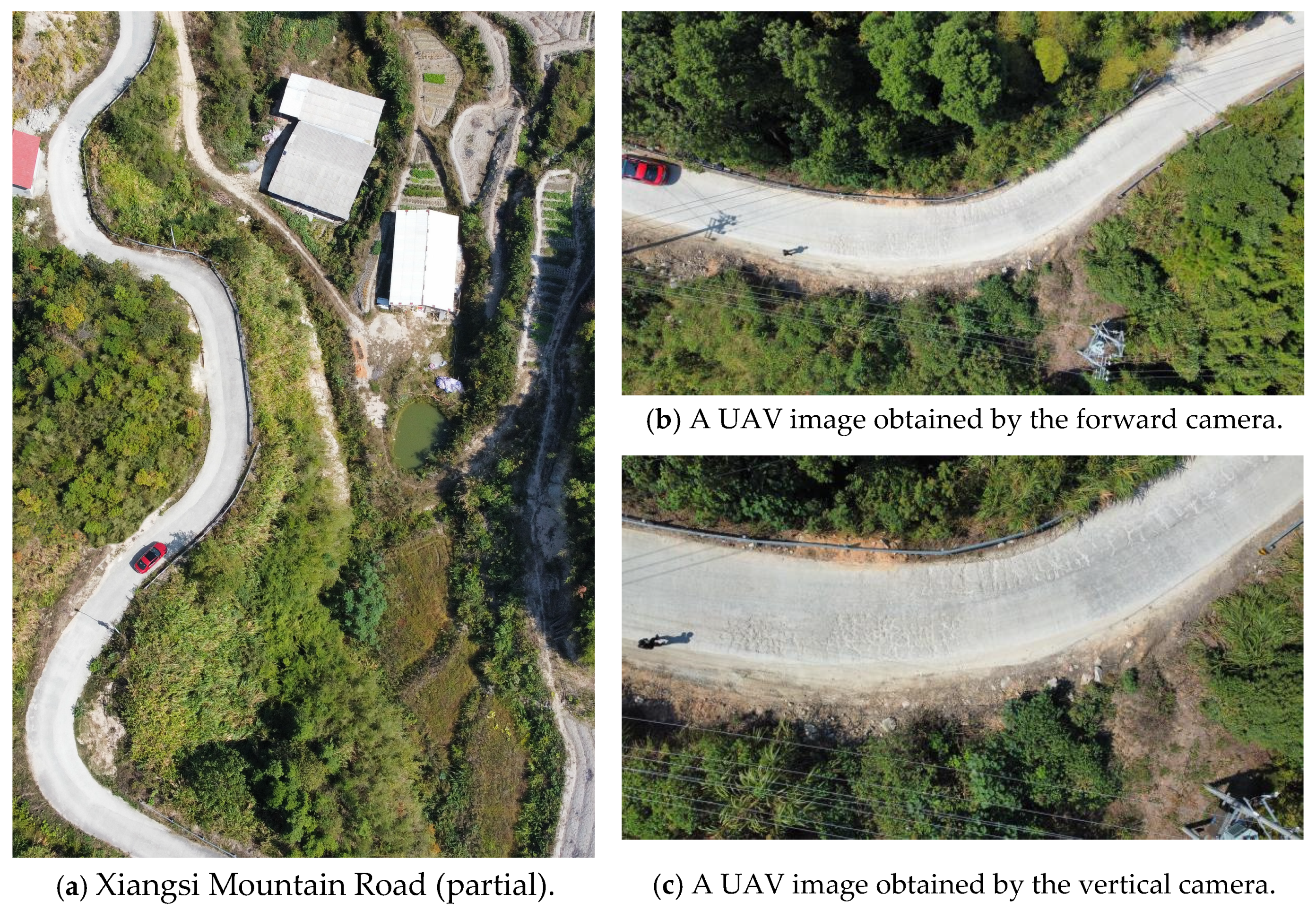
4.1. Experimental Scenarios
4.2. Experimental Results
4.2.1. Results for Autonomous Navigation Using UAV Forward Imagery
- (1)
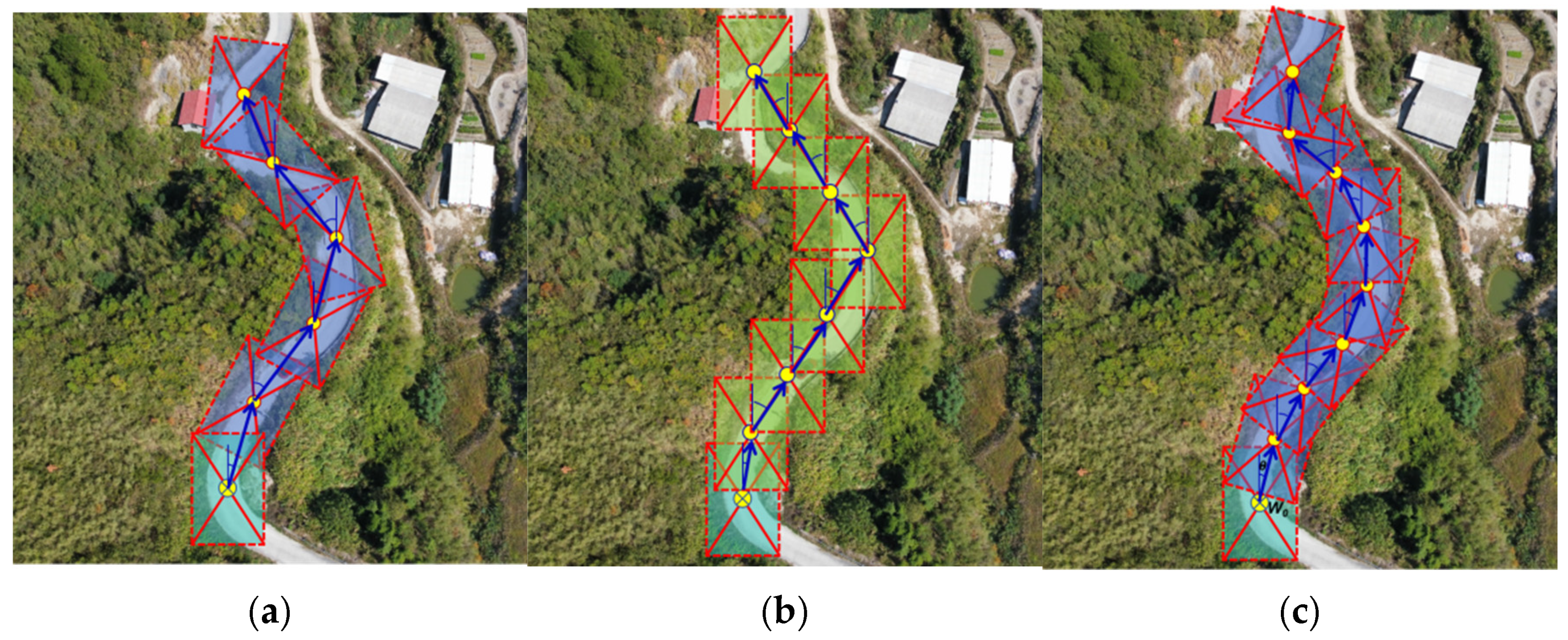
- Three strategies of visual windows for route generation
- (2)
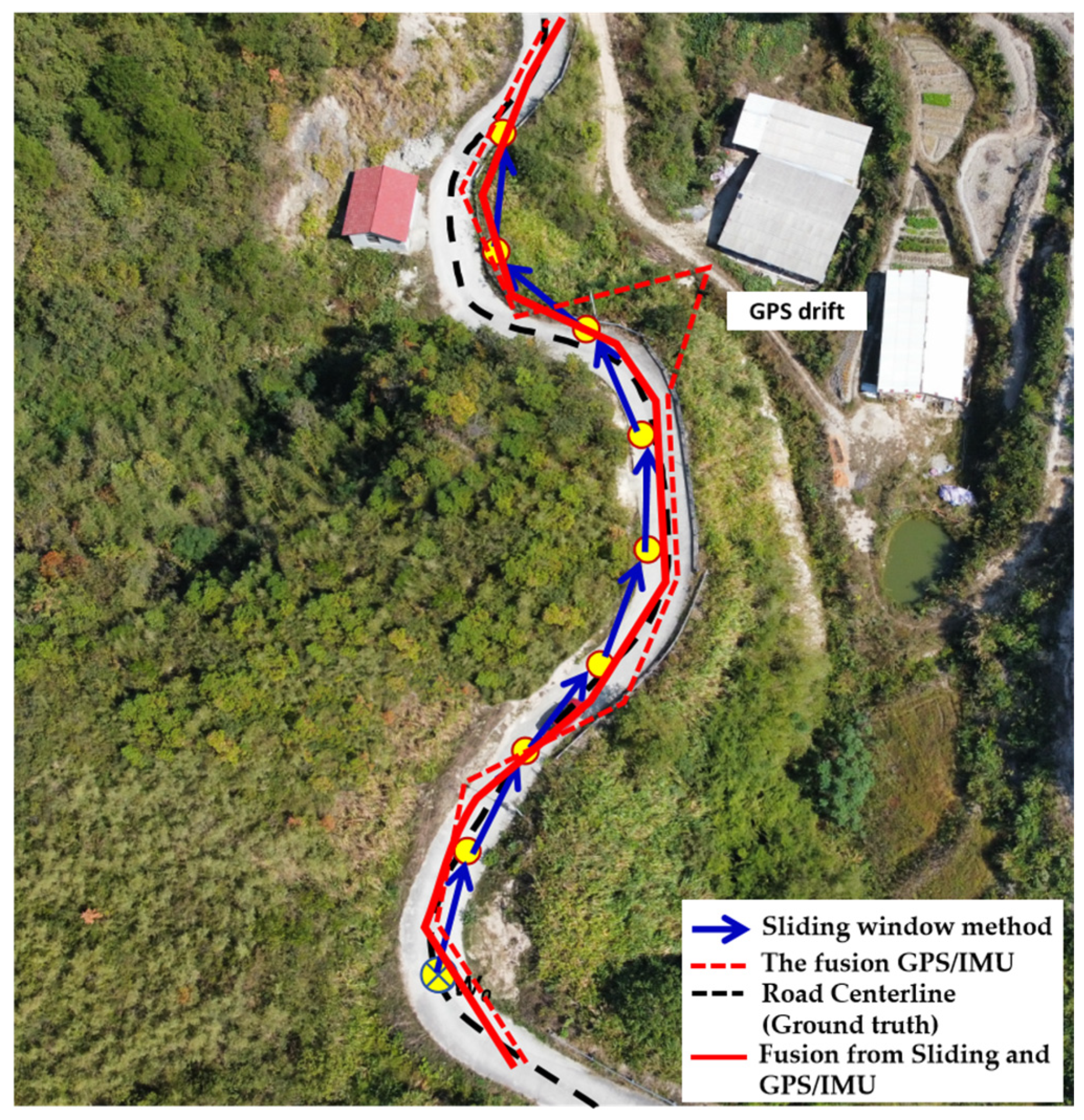
- Comparison of the route generation results
4.2.2. Results for Autonomous Crack Detection Using UAV Vertical Imagery
- (1)
- The running performance of the autonomous crack detection
- (2)
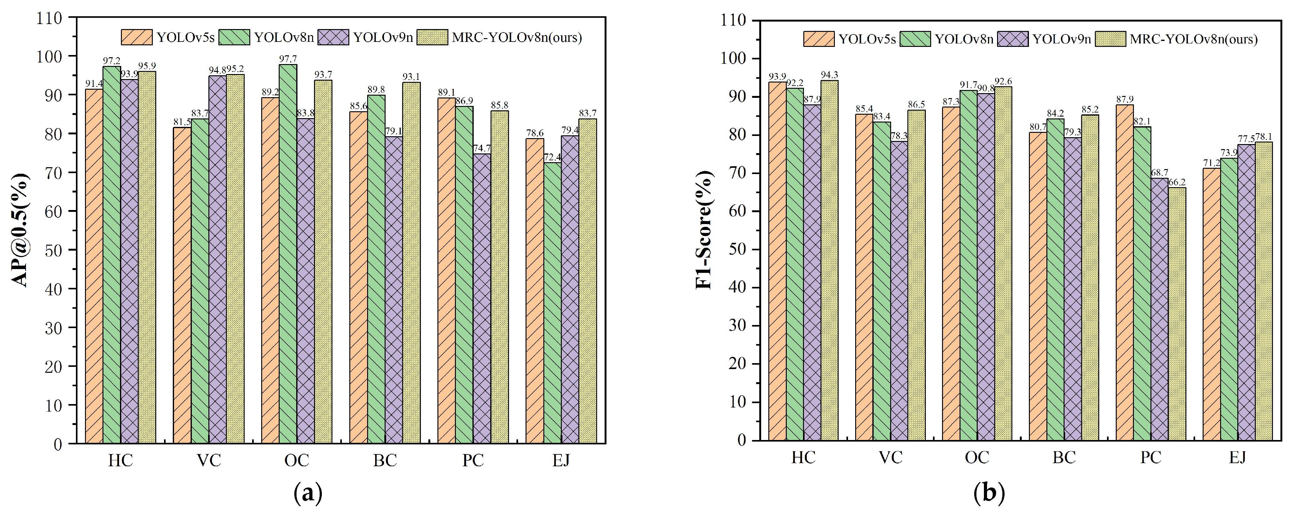
- The identification accuracy of the autonomous crack detection
- (3)
- The visual detection results based on improved YOLOv8
5. Discussion
6. Conclusions
Author Contributions
Funding
Institutional Review Board Statement
Informed Consent Statement
Data Availability Statement
Acknowledgments
Conflicts of Interest
References
- Jiang, Y.T.; Yan, H.T.; Zhang, Y.R.; Wu, K.Q.; Liu, R.Y.; Lin, C.Y. RDD-YOLOv5: Road Defect Detection Algorithm with Self-Attention Based on Unmanned Aerial Vehicle Inspection. Sensors 2023, 23, 8241. [Google Scholar] [CrossRef] [PubMed]
- Guo, S.; Xu, Z.; Li, X.; Zhu, P. Detection and Characterization of Cracks in Highway Pavement with the Amplitude Variation of GPR Diffracted Waves: Insights from Forward Modeling and Field Data. Remote Sens. 2022, 14, 976. [Google Scholar] [CrossRef]
- Zhao, Y.; Zhou, L.; Wang, X.; Wang, F.; Shi, G. Highway Crack Detection and Classification Using UAV Remote Sensing Images Based on CrackNet and CrackClassification. Appl. Sci. 2023, 13, 7269. [Google Scholar] [CrossRef]
- Lai, L. Beautiful Travel. 2022. Available online: http://mms2.baidu.com/it/u=767749105,3305563617&fm=253&app=138&f=JPEG?w=607&h=403 (accessed on 20 April 2024).
- Zhu, J.; Zhong, J.; Ma, T.; Huang, X.; Zhang, W.; Zhou, Y. Pavement distress detection using convolutional neural networks with images captured via UAV. Autom. Constr. 2022, 133, 103991. [Google Scholar] [CrossRef]
- Yu, C.; Yang, Y.; Cheng, Y.; Wang, Z.; Shi, M.; Yao, Z. UAV-based pipeline inspection system with Swin Transformer for the EAST. Fusion Eng. Des. 2022, 184, 113277. [Google Scholar] [CrossRef]
- Ma, Y.; Li, Q.; Chu, L.; Zhou, Y.; Xu, C. Real-Time Detection and Spatial Localization of Insulators for UAV Inspection Based on Binocular Stereo Vision. Remote Sens. 2021, 13, 230. [Google Scholar] [CrossRef]
- Liu, K. Learning-based defect recognitions for autonomous UAV inspections. arXiv 2023, arXiv:2302.06093v1. [Google Scholar]
- Chen, X.; Zhu, X.; Liu, C. Real-Time 3D Reconstruction of UAV Acquisition System for the Urban Pipe Based on RTAB-Map. Appl. Sci. 2023, 13, 13182. [Google Scholar] [CrossRef]
- Metni, N.; Hamel, T. A UAV for bridge inspection: Visual servoing control law with orientation limits. Autom. Constr. 2007, 17, 3–10. [Google Scholar] [CrossRef]
- Zhou, Q.; Ding, S.; Qing, G.; Hu, J. UAV vision detection method for crane surface cracks based on Faster R-CNN and image segmentation. J. Civ. Struct. Health Monit. 2022, 12, 845–855. [Google Scholar] [CrossRef]
- Xiang, X.; Hu, H.; Ding, Y.; Zheng, Y.; Wu, S. GC-YOLOv5s: A Lightweight Detector for UAV Road Crack Detection. Appl. Sci. 2023, 13, 11030. [Google Scholar] [CrossRef]
- Wang, X.; Gao, H.; Jia, Z.; Li, Z. BL-YOLOv8: An Improved Road Defect Detection Model Based on YOLOv8. Sensors 2023, 23, 8361. [Google Scholar] [CrossRef] [PubMed]
- Soumen, J.; Thangam, S.; Anem, K.; Venkata, S.; Saddapalli, V. Transfer Learning Based Deep Convolutional Neural Network Model for Pavement Crack Detection from Images. Int. J. Nonlinear Anal. Appl. 2022, 13, 1209–1223. [Google Scholar] [CrossRef]
- Krizhevsky, A.; Sutskever, I.; Hinton, G.E. ImageNet classification with deep convolutional neural networks. Commun. ACM 2017, 60, 84–90. [Google Scholar] [CrossRef]
- Xu, X.; Zhao, M.; Shi, P.; Ren, R.; He, X.; Wei, X.; Yang, H. Crack detection and comparison study based on faster R-CNN and mask R-CNN. Sensors 2022, 22, 1215. [Google Scholar] [CrossRef] [PubMed]
- Meftah, I.; Hu, J.; Asham, M.A.; Meftah, A.; Zhen, L.; Wu, R. Deep Learning for Autonomous Vehicle Road Crack Visual Detection. Sensors 2024, 24, 1647. [Google Scholar] [CrossRef] [PubMed]
- Su, W.; Wang, J. Research on Road Crack Detection Model Based on YOLOv3 Deep Learning Algorithm. China J. Highw. Transp. 2023, 43, 123–132. [Google Scholar]
- Zhou, S.; Yang, D.; Pan, Y.; Ding, J.; Ding, Y. Detection and Recognition of YOLOv5 Pavement Cracks Based on Attention Mechanism. J. East China Jiaotong Univ. 2023, 52, 321–330. [Google Scholar]
- Ultralytics. YOLOv8. 2023. Available online: https://github.com/ultralytics/ultralytics (accessed on 26 January 2023).
- Wang, G.; Chen, Y.; An, P.; Hong, H.; Hu, J.; Huang, T. UAV-YOLOv8: A Small-Object-Detection Model Based on Improved YOLOv8 for UAV Aerial Photography Scenarios. Sensors 2023, 23, 7190. [Google Scholar] [CrossRef]
- Chen, X.; Liu, C.; Chen, L.; Zhu, X.; Zhang, Y.; Wang, C. A Pavement Crack Detection and Evaluation Framework for a UAV Inspection System Based on Deep Learning. Appl. Sci. 2024, 14, 1157. [Google Scholar] [CrossRef]
- Zhang, Y.; Zuo, Z.; Xu, X.; Wu, J.; Zhu, J.; Zhang, H.; Wang, J.; Tian, Y. Road damage detection using UAV images based on multi-level attention mechanism. Autom. Constr. 2022, 144, 104613. [Google Scholar] [CrossRef]
- Omoebamije, O.; Omoniyi, T.M.; Musa, A.; Duna, S. An improved deep learning convolutional neural network for crack detection based on UAV images. Innov. Infrastruct. Solut. 2023, 8, 236. [Google Scholar] [CrossRef]
- Samadzadegan, F.; Dadrass Javan, F.; Hasanlou, M.; Gholamshahi, M.; Ashtari Mahini, F. Automatic Road Crack Recognition Based on Deep Learning Networks from UAV Imagery. ISPRS Ann. Photogramm. Remote Sens. Spatial Inf. Sci. 2022, X-4/W1-202, 685–690. [Google Scholar] [CrossRef]
- Suwandi, B.; Kitasuka, T.; Aritsugi, M. Low-cost IMU and GPS fusion strategy for apron vehicle positioning. In Proceedings of the IEEE Region 10th Conference (TENCON), Penang, Malaysia, 5–8 November 2017; pp. 449–454. [Google Scholar] [CrossRef]
- Li, D.; Li, Q.; Cheng, N.; Song, J. Sampling-Based Real-Time Motion Planning under State Uncertainty for Autonomous Micro-Aerial Vehicles in GPS-Denied Environments. Sensors 2014, 14, 21791–21825. [Google Scholar] [CrossRef] [PubMed]
- Lee, Y.; Yoon, J.; Yang, H.; Kim, C.; Lee, D. Camera-GPS-IMU sensor fusion for autonomous flying. In Proceedings of the 2016 Eighth International Conference on Ubiquitous and Future Networks (ICUFN), Vienna, Austria, 5–8 July 2016; pp. 85–88. [Google Scholar] [CrossRef]
- Rizk, M.; Mroue, A.; Farran, M.; Charara, J. Real-Time SLAM Based on Image Stitching for Autonomous Navigation of UAVs in GNSS-Denied Regions. In Proceedings of the 2nd IEEE International Conference on Artificial Intelligence Circuits and Systems (AICAS), Genova, Italy, 31 August–2 September 2020; pp. 301–304. [Google Scholar] [CrossRef]
- Çağlar, F.O.; Özgenel, R. Concrete Crack Images for Classification. Mendeley Data 2019, V2. [Google Scholar] [CrossRef]
- Zhang, Y.F.; Ren, W.; Zhang, Z.; Jia, Z.; Wang, L.; Tan, T. Focal and efficient IOU loss for accurate bounding box regression. Neurocomputing 2022, 506, 146–157. [Google Scholar] [CrossRef]
- Zheng, Z.; Wang, P.; Liu, W.; Li, J.; Ye, R.; Ren, D. Distance-IoU loss: Faster and better learning for bounding box regression. In Proceedings of the AAAI Conference on Artificial Intelligence, New York, NY, USA, 7–12 February 2020; pp. 12993–13000. [Google Scholar] [CrossRef]
- Wei, H.; Liu, X.; Xu, S.-t.; Dai, Z.; Dai, Y.; Xu, X. DWRSeg: Rethinking Efficient Acquisition of Multi-scale Contextual Information for Real-time Semantic Segmentation. arXiv 2022, arXiv:2212.01173. [Google Scholar]
- Wong, K.Y. YOLOv7. 2023. Available online: https://github.com/WongKinYiu/yolov7 (accessed on 26 January 2023).
- Xing, J.; Liu, Y.; Zhang, G. Concrete Highway Crack Detection Based on Visible Light and Infrared Silicate Spectrum Image Fusion. Sensors 2024, 24, 2759. [Google Scholar] [CrossRef] [PubMed]
- Georgia Tech Research Institute. Automated Pavement Crack Detection and Sealing Prototype System. 2022. Available online: https://www.newswise.com/articles/automated-pavement-crack-detection-and-sealing-prototype-system-developed-by-gtri (accessed on 26 January 2024).
- Yang, B.; Zong, Z.; Chen, C.; Sun, W.; Mi, X.; Wu, W.; Huang, R. Real time approach for underground objects detection from vehicle-borne ground penetrating radar. Acta Geod. Cartogr. Sin. 2020, 49, 874–882.e54. [Google Scholar] [CrossRef]
- Wu, H.; Yao, L.; Xu, Z.; Li, Y.; Ao, X.; Chen, Q.; Li, Z.; Meng, B. Road pothole extraction and safety evaluation by integration of point cloud and images derived from mobile mapping sensor. Adv. Eng. Inform. 2019, 42, 100936. [Google Scholar] [CrossRef]


| Hardware Device | Model | Specification |
|---|---|---|
| Visual Sensors (CMOS) | HIKVISION DS-E12 (Hikvision, Shenzhen, China) SPLIT-HDMI-CV2 (RunCam, Shenzhen, China) | RGB Resolution: 1920 × 1080; Pixels@30 FPS; Total Weight: 120 g; RGB Resolution: 1920 × 1080; Pixels@60 FPS; Total Weight: 22 g; |
| Mini-computer (Onboard) | NUC11 TNKi5 (Intel, Chandler, AZ, USA) | Operating System: Ubuntu18.04; Processor: Intel I5-1145G7 Memory: 8 GB, DDR4, 3200 MHz; Total Weight: 596 g; |
| Flight Controller | Pixhawk 6C, V2.4.8 (Chibei, Xuzhou, China) | Max input Voltage: 6 V; Power: 4.8 W; Operating temperature: −10°~+55°; Total Weight: 59.3 g; |
| Electronic Speed Control | Formula 32 bit 45 A ESC (Uangel, Shenzhen, China) | Persistent Current: 45 A; BEC: 10 V/2 A; Total Weight: 28.8 g; |
| GPS/IMU | WTG AHRS2 (WitMotion, Shenzhen, China) | Voltage: 3.3~5 V; Current: <40 mA; Angle Accuracy: 0.05; |
| Motors—4 | Motor VELOX V2306 (Axisflying, Nanchang, China) | Power: 850 W; KV: 1950; Power ratio: 1.88; Total Weight: 128 g; |
| Battery | Gens ace XT60 4S (Grepow, Shenzhen, China) | Capacity: 8500 mAh; Voltage: 14.8 V; Total Weight: 680 g; |
| Having Damage with Cracks (Cracks) | No Damage | |||||
|---|---|---|---|---|---|---|
| Horizontal Cracks (HCs) | Vertical Cracks (VCs) | Oblique Cracks (OCs) | Block Cracks (BCs) | Pothole Cracks (PCs) | Expansion Joints (EJs) | No-Crack (NC) Background |
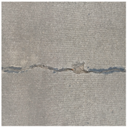 |  | 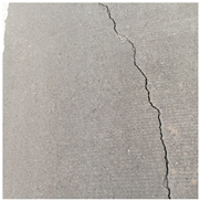 | 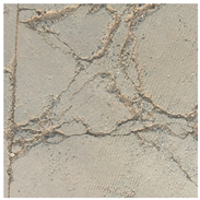 |  | 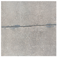 |  |
| Software | Configures | Matrix | Versions |
|---|---|---|---|
| Operating system | Ubuntu 20.4 | Python | 3.8 |
| CPU | Intel(R) Xeon(R) Platinum 8352 V | PyTorch | 1.11.0 |
| GPU | RTX 4090 (24 GB) | CUDA | 11.3 |
| Memory | Samsung 64 GB |
| RMSE | X Axis RMSE | Y Axis RMSE | H Axis RMSE | Total Distance RMSE |
|---|---|---|---|---|
| The Sliding Window Method (SWM) | 0.58 | 1.64 | --- | 0.431 |
| GPS only | 0.51 | 1.95 | 0.571 | 0.544 |
| The fusion of GPS/IMU | 0.46 | 1.67 | 0.323 | 0.427 |
| The final fusion results with SWM | 0.46 | 1.52 | 0.219 | 0.339 |
| Models | Number of Parameters (×106) | Training Duration (h) | Memory Consumption (MB) | FPS (f·s−1) |
|---|---|---|---|---|
| YOLO v5s | 7.02 | 1.44 | 14.5 | 146.14 |
| YOLO v8n | 3.00 | 1.36 | 6.3 | 140.68 |
| YOLO v9n | 50.97 | 3.05 | 102.9 | 42.786 |
| MRC-YOLOv8 (ours) | 2.81 | 1.12 | 11.4 | 152.73 |
| Models | Precision (P) | Recall (R) | F1-Score | mAP |
|---|---|---|---|---|
| YOLO v5s | 82.3 | 80.1 | 81.7 | 90.9 |
| YOLO v8n | 87.4 | 86.4 | 86.9 | 91.0 |
| YOLO v9n | 82.5 | 76.7 | 79.5 | 85.3 |
| MRC-YOLOv8 (our) | 90.7 | 89.8 | 87.4 | 92.3 |
| Models | [email protected] (%) | F1-Score (%) | ||||||||||
|---|---|---|---|---|---|---|---|---|---|---|---|---|
| HCs | VCs | OCs | BCs | PCs | EJs | HCs | VCs | OCs | BCs | PCs | EJs | |
| YOLO v5s | 91.4 | 81.5 | 89.2 | 85.6 | 89.1 | 78.6 | 93.9 | 85.4 | 87.3 | 80.7 | 87.9 | 71.2 |
| YOLO v8n | 97.2 | 83.7 | 97.7 | 89.8 | 86.9 | 72.4 | 92.2 | 83.4 | 91.7 | 84.2 | 82.1 | 73.9 |
| YOLO v9n | 93.9 | 94.8 | 83.8 | 79.1 | 74.7 | 79.4 | 87.9 | 78.3 | 90.8 | 79.3 | 68.7 | 77.5 |
| MRC-YOLOv8 (ours) | 95.9 | 95.2 | 93.7 | 93.1 | 85.8 | 83.7 | 94.3 | 86.5 | 92.6 | 85.2 | 66.2 | 78.1 |
| Systems | Main Sensors | Detection Methods | Advantages and Disadvantages |
|---|---|---|---|
| Sealing Prototype System [36] | Stereo Camera | Image Processing and Deep Learning |
|
| Multi-function detection vehicles [37,38] | 3D GPR/3D Laser Scanning | Transmitted Wave Method |
|
| UAV System [3,5,8,21,23,25] | Cameras | Image processing and Deep Learning |
|
| UAV Autonomous Inspection System (Ours) | Cameras | Image processing and Deep Learning |
|
Disclaimer/Publisher’s Note: The statements, opinions and data contained in all publications are solely those of the individual author(s) and contributor(s) and not of MDPI and/or the editor(s). MDPI and/or the editor(s) disclaim responsibility for any injury to people or property resulting from any ideas, methods, instructions or products referred to in the content. |
© 2024 by the authors. Licensee MDPI, Basel, Switzerland. This article is an open access article distributed under the terms and conditions of the Creative Commons Attribution (CC BY) license (https://creativecommons.org/licenses/by/4.0/).
Share and Cite
Chen, X.; Wang, C.; Liu, C.; Zhu, X.; Zhang, Y.; Luo, T.; Zhang, J. Autonomous Crack Detection for Mountainous Roads Using UAV Inspection System. Sensors 2024, 24, 4751. https://doi.org/10.3390/s24144751
Chen X, Wang C, Liu C, Zhu X, Zhang Y, Luo T, Zhang J. Autonomous Crack Detection for Mountainous Roads Using UAV Inspection System. Sensors. 2024; 24(14):4751. https://doi.org/10.3390/s24144751
Chicago/Turabian StyleChen, Xinbao, Chenxi Wang, Chang Liu, Xiaodong Zhu, Yaohui Zhang, Tianxiang Luo, and Junhao Zhang. 2024. "Autonomous Crack Detection for Mountainous Roads Using UAV Inspection System" Sensors 24, no. 14: 4751. https://doi.org/10.3390/s24144751