
Graphene-Based Tunable Polarization Conversion Metasurface for Array Antenna Radar Cross-Section Reduction


Abstract
:1. Introduction
2. Design of Polarization Conversion Unit
2.1. Simulation Setup
2.2. Graphene Material
2.3. Polarization Conversion Theory
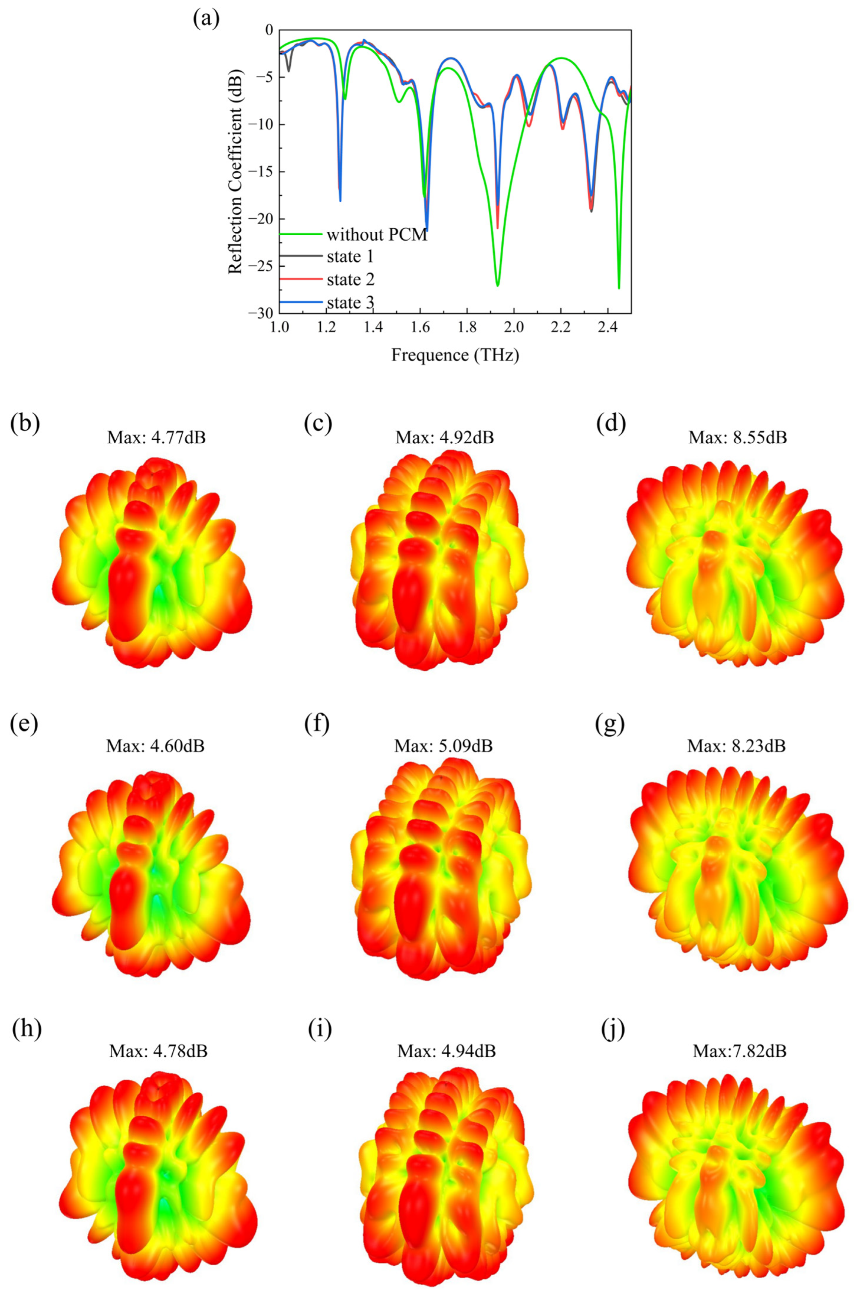
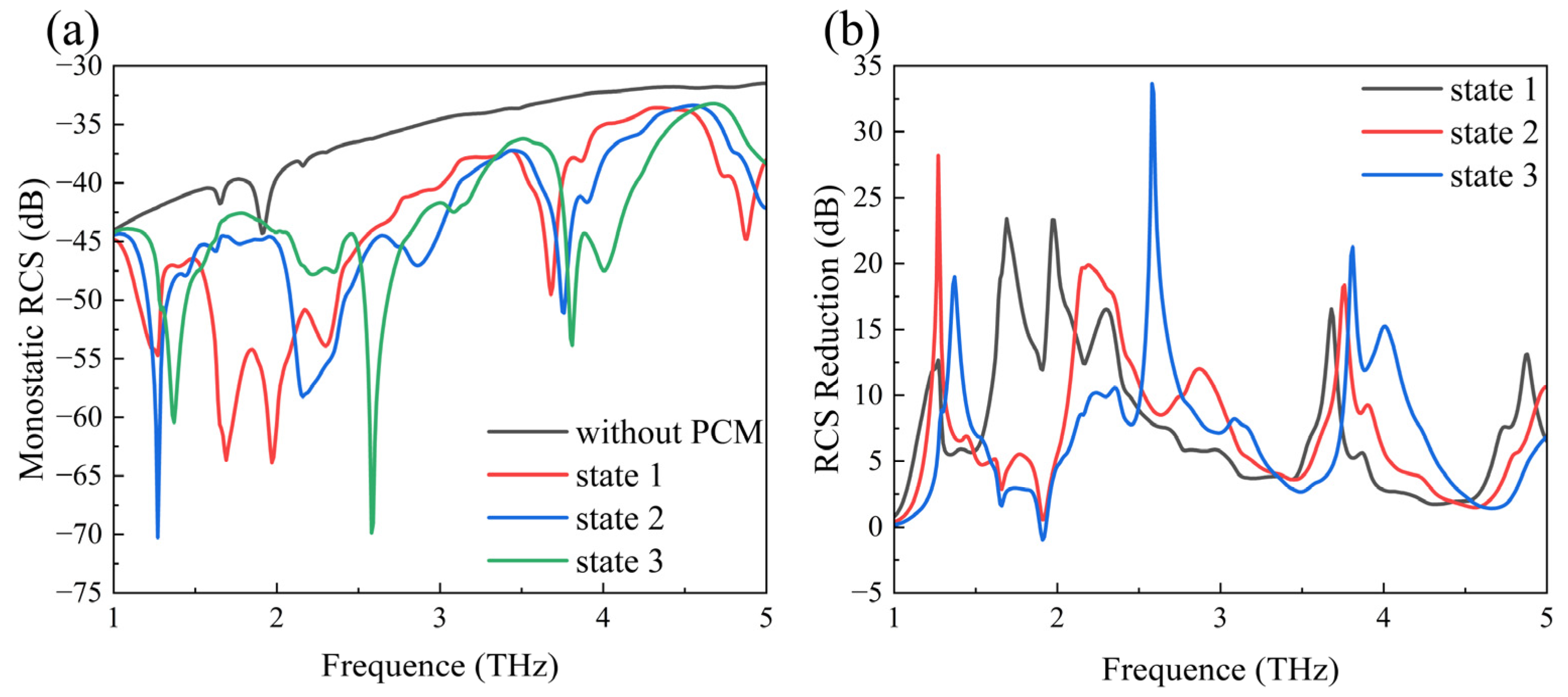
3. Application of PCM in Array Antennas
4. Conclusions
Author Contributions
Funding
Institutional Review Board Statement
Informed Consent Statement
Data Availability Statement
Conflicts of Interest
References
- Pang, Y.Q.; Shen, Y.; Li, Y.F.; Wang, J.F.; Xu, Z.; Qu, S.B. Water-based metamaterial absorbers for optical transparency and broadband microwave absorption. J. Appl. Phys. 2018, 123, 155106. [Google Scholar] [CrossRef]
- Qi, D.; Wang, X.; Cheng, Y.Z.; Gong, R.Z.; Li, B.W. Design and characterization of one-dimensional photonic crystals based on ZnS/Ge for infrared-visible compatible stealth applications. Opt. Mater. 2016, 62, 52–56. [Google Scholar] [CrossRef]
- Xu, C.L.; Wang, B.K.; Pang, Y.Q.; Wang, J.F.; Yan, M.B.; Wang, W.J.; Wang, A.X.; Jiang, J.M.; Qu, S.B. Hybrid metasurfaces for infrared-multiband radar stealth-compatible materials applications. IEEE Access 2019, 7, 147586–147595. [Google Scholar] [CrossRef]
- Li, W.C.; Zhang, B.H.; Ying, Y.; Yu, J.; Zheng, J.W.; Qiao, L.; Li, J.; Che, S.L. An optically transparent unequal proportional coding metasurface with absorption and diffusion integrated mechanism for ultra-broadband RCS reduction. Opt. Mater. 2022, 133, 112801. [Google Scholar] [CrossRef]
- Xu, H.X.; Ma, S.J.; Ling, X.H.; Zhang, X.K.; Tang, S.W.; Cai, T.; Sun, S.L.; He, Q.; Zhou, L. Deterministic approach to achieve broadband polarization-independent diffusive scatterings based on metasurfaces. ACS Photonics 2018, 5, 1691–1702. [Google Scholar] [CrossRef]
- Yang, J.J.; Liao, Z.Q.; Li, Y.R.; Li, D.M.; Wang, Z.K.; Wang, T.; Wang, X.; Gong, R.Z. Phase modulation of metasurfaces for polarization conversion and RCS reduction. Opt. Mater. 2021, 119, 111374. [Google Scholar] [CrossRef]
- Zhu, H.Z.; Li, Q.; Tao, C.N.; Hong, Y.; Xu, Z.Q.; Shen, W.D.; Kaur, S.; Ghosh, P.; Qiu, M. Multispectral camouflage for infrared, visible, lasers and microwave with radiative cooling. Nat. Commun. 2021, 12, 1805. [Google Scholar] [CrossRef]
- Bilal, R.M.H.; Naveed, M.A.; Baqir, M.A.; Ali, M.M.; Rahim, A.A. Design of a wideband terahertz metamaterial absorber based on Pythagorean-tree fractal geometry. Opt. Mater. Express 2020, 10, 3007–3020. [Google Scholar] [CrossRef]
- Kang, J.F.; Qu, Z.; Duan, J.P.; Jing, H.H.; Hao, J.X.; Song, C.W.; Wang, J.Y.; Zhang, B.Z. Multispectral flexible ultrawideband metamaterial absorbers for radar stealth and visible light transparency. Opt. Mater. 2023, 135, 113351. [Google Scholar] [CrossRef]
- Zhang, Y.; Xue, W.R.; Du, Y.D.; Liang, J.L.; Li, C.Y. Bi-functional metasurface for broadband absorption and broadband cross-polarization conversion based on vanadium dioxide. Opt. Mater. 2024, 149, 114984. [Google Scholar] [CrossRef]
- Naveed, M.A.; Bilal, R.M.H.; Rahim, A.A.; Baqir, M.A.; Ali, M.M. Polarization-insensitive dual-wideband fractal meta-absorber for terahertz applications. Appl. Optics 2021, 60, 9160–9166. [Google Scholar] [CrossRef]
- Yin, W.; Shen, Z.L.; Li, S.N.; Gao, F.; Hao, H.B.; Zhang, L.Y.; Chen, X.F. Flexible broadband terahertz absorbers for RCS reduction on conformal surfaces. Opt. Commun. 2022, 520, 128502. [Google Scholar] [CrossRef]
- Zhang, M.; Zhang, N.J.; Dong, P.; Yang, L.; Wang, B.Z.; Wu, R.H.; Hou, W.M. All-Metal Coding Metasurfaces for Broadband Terahertz RCS Reduction and Infrared Invisibility. Photonics 2023, 10, 962. [Google Scholar] [CrossRef]
- Wang, Y.Y.; Zhang, X.L.; Zhan, X.; Zhang, T.W.; Zhou, L.M.; Shi, J.; Wei, S.J. An RCS measurement method using sparse imaging based 3-D SAR complex image. IEEE Antennas Wireless Propag. Lett. 2022, 21, 24–28. [Google Scholar] [CrossRef]
- Landy, N.I.; Sajuyigbe, S.; Mock, J.J.; Smith, D.R.; Padilla, W.J. Perfect metamaterial absorber. Phys. Rev. Lett. 2008, 100, 207402. [Google Scholar] [CrossRef]
- Shen, X.P.; Cui, T.J.; Zhao, J.M.; Ma, H.F.; Jiang, W.X.; Li, H. Polarization-independent wide-angle triple-band metamaterial absorber. Opt. Express 2011, 19, 9401–9407. [Google Scholar] [CrossRef]
- Liu, X.L.; Starr, T.; Starr, A.F.; Padilla, W.J. Infrared spatial and frequency selective metamaterial with near-unity absorbance. Phys. Rev. Lett. 2010, 104, 207403. [Google Scholar] [CrossRef]
- Cui, T.J.; Qi, M.Q.; Wan, X.; Zhao, J.; Cheng, Q. Coding metamaterials, digital metamaterials and programmable metamaterials. Light-Sci. Appl. 2014, 3, e218. [Google Scholar] [CrossRef]
- Chen, W.G.; Balanis, C.A.; Birtcher, C.R. Checkerboard EBG surfaces for wideband radar cross section reduction. IEEE Trans. Antennas Propag. 2015, 63, 2636–2645. [Google Scholar] [CrossRef]
- Su, J.X.; Lu, Y.; Liu, J.Y.; Yang, Y.Q.; Li, Z.R.; Song, J.M. A novel checkerboard metasurface based on optimized multielement phase cancellation for superwideband RCS reduction. IEEE Trans. Antennas Propag. 2018, 66, 7091–7099. [Google Scholar] [CrossRef]
- Li, T.; Yang, H.H.; Li, Q.; Zhu, X.W.; Cao, X.Y.; Gao, J.; Wu, Z.B. Dual-polarised and ultra-thin broadband AAMCs for both P and L bands applications. IET Microw. Antennas Propag. 2019, 13, 185–189. [Google Scholar] [CrossRef]
- Grady, N.K.; Heyes, J.E.; Chowdhury, D.R.; Zeng, Y.; Reiten, M.T.; Azad, A.K.; Taylor, A.J.; Dalvit, D.A.R.; Chen, H.T. Terahertz metamaterials for linear polarization conversion and anomalous refraction. Science 2013, 340, 1304–1307. [Google Scholar] [CrossRef]
- Chen, H.Y.; Wang, J.F.; Ma, H.; Qu, S.B.; Xu, Z.; Zhang, A.X.; Yan, M.B.; Li, Y.F. Ultra-wideband polarization conversion metasurfaces based on multiple plasmon resonances. J. Appl. Phys. 2014, 115, 154504. [Google Scholar] [CrossRef]
- Gao, X.; Han, X.; Cao, W.P.; Li, H.O.; Ma, H.F.; Cui, T.J. Ultrawideband and high-efficiency linear polarization converter based on double V-shaped metasurface. IEEE Trans. Antennas Propag. 2015, 63, 3522–3530. [Google Scholar] [CrossRef]
- Yang, H.H.; Cao, X.Y.; Yang, F.; Gao, J.; Xu, S.H.; Li, M.K.; Chen, X.B.; Zhao, Y.; Zheng, Y.J.; Li, S.J. A programmable metasurface with dynamic polarization, scattering and focusing control. Sci. Rep. 2016, 6, 35692. [Google Scholar] [CrossRef]
- Liu, Z.M.; Liu, S.B.; Bornemann, J.; Zhao, X.; Kong, X.K.; Huang, Z.Y.; Bian, B.R.; Wang, D.D. A low-RCS, high-GBP Fabry–Perot antenna with embedded chessboard polarization conversion metasurface. IEEE Access 2020, 8, 80183–80194. [Google Scholar] [CrossRef]
- Liu, Y.; Li, K.; Jia, Y.T.; Hao, Y.W.; Gong, S.X.; Guo, Y.J. Wideband RCS reduction of a slot array antenna using polarization conversion metasurfaces. IEEE Trans. Antennas Propag. 2016, 64, 326–331. [Google Scholar] [CrossRef]
- Geim, A.K. Graphene: Status and prospects. Science 2009, 324, 1530–1534. [Google Scholar] [CrossRef]
- Papasimakis, N.; Luo, Z.Q.; Shen, Z.X.; De Angelis, F.; Di Fabrizio, E.; Nikolaenko, A.E.; Zheludev, N.I. Graphene in a photonic metamaterial. Opt. Express 2010, 18, 8353–8359. [Google Scholar] [CrossRef]
- Wu, J.L.; Yan, X.; Yuan, X.G.; Zhang, Y.G.; Zhang, X. A dual-tunable ultra-broadband terahertz absorber based on graphene and strontium titanate. Results Phys. 2021, 31, 105039. [Google Scholar] [CrossRef]
- Hanson, G.W. Dyadic Green’s functions and guided surface waves for a surface conductivity model of graphene. J. Appl. Phys. 2008, 103, 064302. [Google Scholar] [CrossRef]
- Chen, M.; Sun, W.; Cai, J.J.; Chang, L.Z.; Xiao, X.F. Frequency-tunable mid-infrared cross polarization converters based on graphene metasurface. Plasmonics 2017, 12, 699–705. [Google Scholar] [CrossRef]
- Yuan, X.G.; Chen, J.Y.; Wu, J.L.; Yan, X.; Zhang, Y.A.; Zhang, X. Graphene-based tunable linear and linear-to-circular polarization converters in the THz band. Results Phys. 2022, 37, 105571. [Google Scholar] [CrossRef]
- Zhang, J.N.; Tao, S.J.; Yan, X.; Zhang, X.; Guo, J.X.; Wen, Z.Q. Dual-Frequency Polarized Reconfigurable Terahertz Antenna Based on Graphene Metasurface and TOPAS. Micromachines 2021, 12, 1088. [Google Scholar] [CrossRef]
- Wei, B.H.; Li, Y.; Yun, T.H.; Li, Y.; Gui, T.H.; Yu, W.Z.; Mu, H.R.; Cui, N.; Chen, W.Q.; Lin, S.H. Triply degenerate semimetal PtBi2 as van der Waals contact interlayer in two-dimensional transistor. Mater. Futures 2024, 3, 025302. [Google Scholar] [CrossRef]
- Xu, R.; Guo, J.F.; Mi, S.; Wen, H.F.; Pang, F.; Ji, W.; Cheng, Z.H. Advanced atomic force microscopies and their applications in two-dimensional materials: A review. Mater. Futures 2022, 1, 032302. [Google Scholar] [CrossRef]
- Wang, Y.; Mei, L.; Li, Y.; Xia, X.; Cui, N.; Long, G.; Yu, W.; Chen, W.; Mu, H.; Lin, S. Integration of two-dimensional materials based photodetectors for on-chip applications. Phys. Rep. 2024, 1081, 1–46. [Google Scholar] [CrossRef]
- Su, Z.W.; Zhao, Y.J.; Huang, Y.Q.; Xu, C.Y.; Yang, X.L.; Wang, B.R.; Xu, B.B.; Xu, S.Q.; Bai, G.X. Light-driven soft actuator based on graphene and WSe2 nanosheets composite for multimodal motion and remote manipulation. Nano Res. 2023, 16, 1313–1319. [Google Scholar] [CrossRef]
- Gong, Y.N.; Xu, Z.Q.; Li, D.L.; Zhang, J.; Aharonovich, I.; Zhang, Y.P. Two-Dimensional Hexagonal Boron Nitride for Building Next-Generation Energy-Efficient Devices. ACS Energy Lett. 2021, 6, 985–996. [Google Scholar] [CrossRef]
- Li, Y.L.; Qi, L.M.; Yao, Y.; Liu, X.M.; Chen, Z.J.; Yu, J.S.; Chen, X.D. RCS Reduction Study of THz Microstrip Antenna Based on ITO Absorbing Structure. In Proceedings of the Sixth Asia-Pacific Conference on Antennas and Propagation (APCAP), Xi’an, China, 16–19 October 2017; IEEE: Piscataway, NJ, USA, 2017; pp. 1–3. [Google Scholar]
- Wang, F.W.; Li, K.; Ren, Y.H.; Zhang, Y.Q. A novel reconfigurable FSS applied to the antenna radar cross section reduction. Int. J. RF Microw. Comput.-Aided Eng. 2019, 29, e21729. [Google Scholar] [CrossRef]


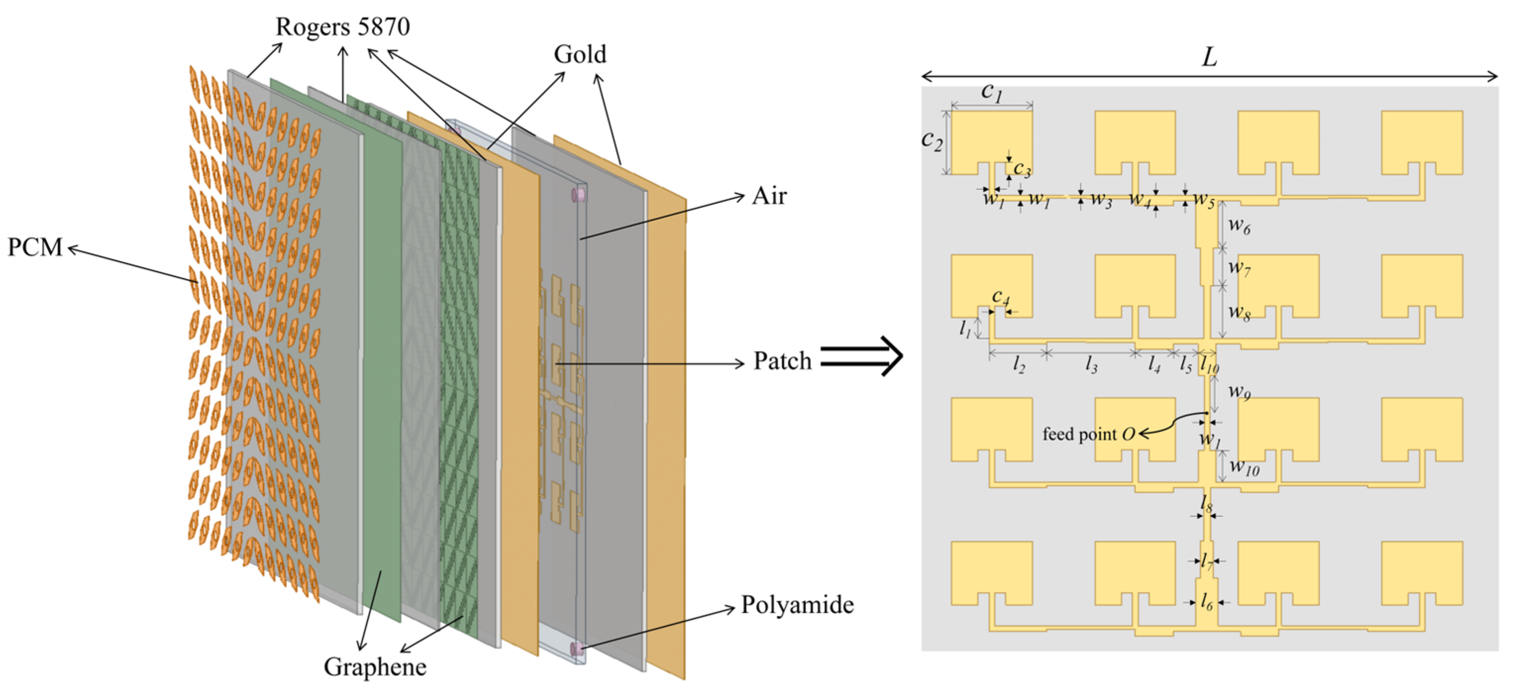
| Parameter | Length (μm) | Parameter | Length (μm) | Parameter | Length (μm) |
|---|---|---|---|---|---|
| L | 60 | m | 28.28 | n | 24.49 |
| r | 8 | h1 | 1 | h2 | 8 |
| h3 | 2 | h | 18 | d | 2 |
| d1 | 3.92 | d2 | 15 |
| Parameter | Length (μm) | Parameter | Length (μm) | Parameter | Length (μm) |
|---|---|---|---|---|---|
| C1 | 58.12 | C2 | 45.53 | C3 | 8.5 |
| C4 | 8 | l1 | 15 | w1 | 3.92 |
| l2 | 41.35 | w2 | 3.92 | l3 | 63.87 |
| w3 | 2.4 | l4 | 27.27 | w4 | 7.53 |
| l5 | 16.4 | w5 | 3.92 | l6 | 15.92 |
| w6 | 34.195 | l7 | 9.26 | w7 | 27.03 |
| l8 | 4.62 | w8 | 38.115 | l9 | 3.92 |
| w9 | 26.95 | l10 | 12.86 | w10 | 22.72 |
| Ref. | Tunability | RCS Reduction Band | Maximum RCS Reduction | Impact on Antenna Performance |
|---|---|---|---|---|
| [26] | No | 8–26 GHz | 21.2 dB | Improved |
| [40] | No | 0.4–0.575 THz | 15 dB | Slightly decreased |
| [41] | Yes | ON-State 2–6 GHz OFF-State 1–8 GHz | 27 dB / | Unchanged |
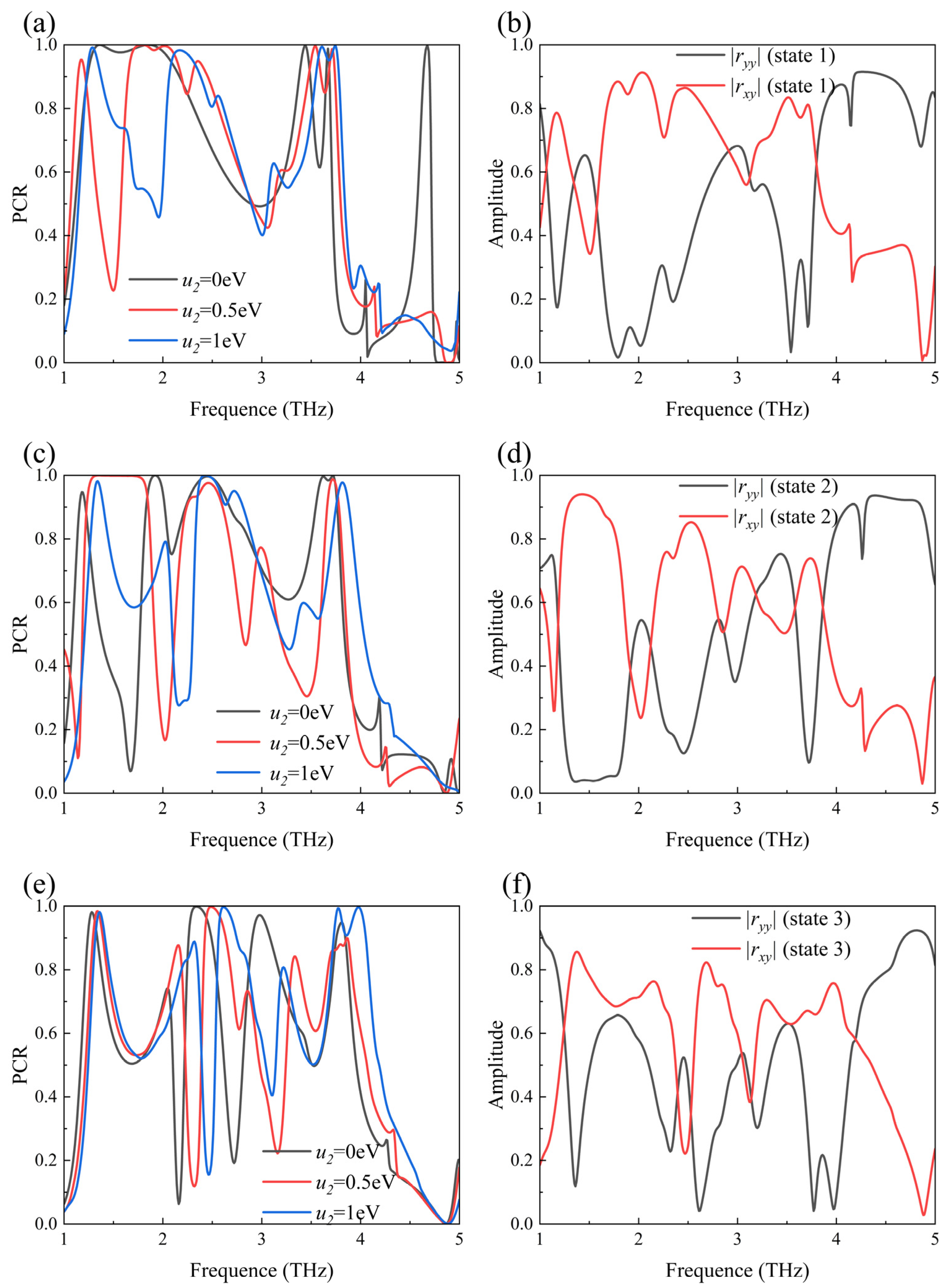
| This paper | Yes | State 1 1.60–2.43 THz 3.63–3.72 THz State 2 2.07–2.53 THz 2.78–2.98 THz 3.70–3.81 THz State 3 1.32–1.43 THz 2.51–2.76 THz 3.76–4.13 THz | 23.3 dB 19.8 dB 24.6 dB | Unchanged |
Disclaimer/Publisher’s Note: The statements, opinions and data contained in all publications are solely those of the individual author(s) and contributor(s) and not of MDPI and/or the editor(s). MDPI and/or the editor(s) disclaim responsibility for any injury to people or property resulting from any ideas, methods, instructions or products referred to in the content. |
© 2024 by the authors. Licensee MDPI, Basel, Switzerland. This article is an open access article distributed under the terms and conditions of the Creative Commons Attribution (CC BY) license (https://creativecommons.org/licenses/by/4.0/).
Share and Cite
Zhang, Y.; Li, Y.; Li, Y.; Yuan, X.; Yan, X.; Zhang, X. Graphene-Based Tunable Polarization Conversion Metasurface for Array Antenna Radar Cross-Section Reduction. Sensors 2024, 24, 5044. https://doi.org/10.3390/s24155044
Zhang Y, Li Y, Li Y, Yuan X, Yan X, Zhang X. Graphene-Based Tunable Polarization Conversion Metasurface for Array Antenna Radar Cross-Section Reduction. Sensors. 2024; 24(15):5044. https://doi.org/10.3390/s24155044
Chicago/Turabian StyleZhang, Yang’an, Yuxi Li, Yao Li, Xueguang Yuan, Xin Yan, and Xia Zhang. 2024. "Graphene-Based Tunable Polarization Conversion Metasurface for Array Antenna Radar Cross-Section Reduction" Sensors 24, no. 15: 5044. https://doi.org/10.3390/s24155044