
RobotSDF: Implicit Morphology Modeling for the Robotic Arm

 ,
,
Abstract
:1. Introduction
- We propose an implicit modeling method for continuous robotic morphology, called RobotSDF, by converting the robot’s overall morphology changing process into the transformation process of query points within the local coordinate of each joint.
- We verify the morphological expression accuracy of the proposed RobotSDF on a six-DOF robotic arm, which can achieve high reconstruction accuracy up to the millimeter level.
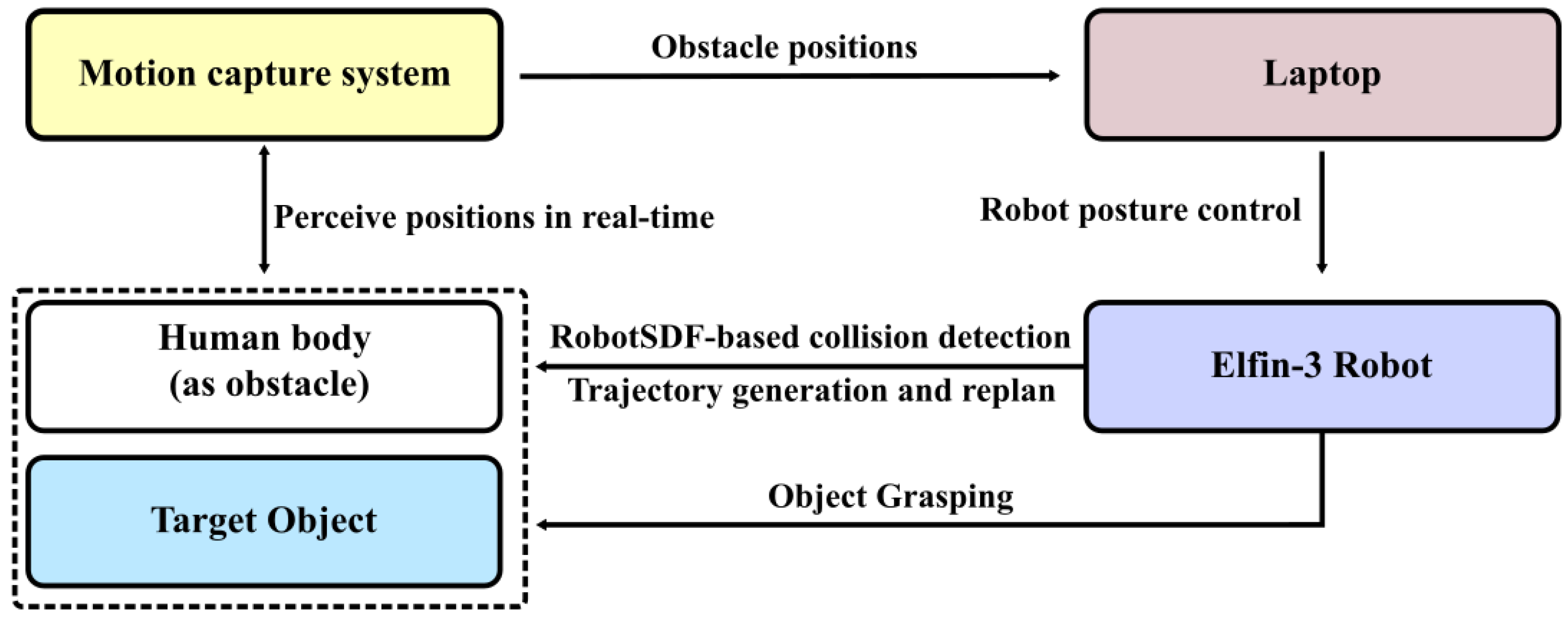
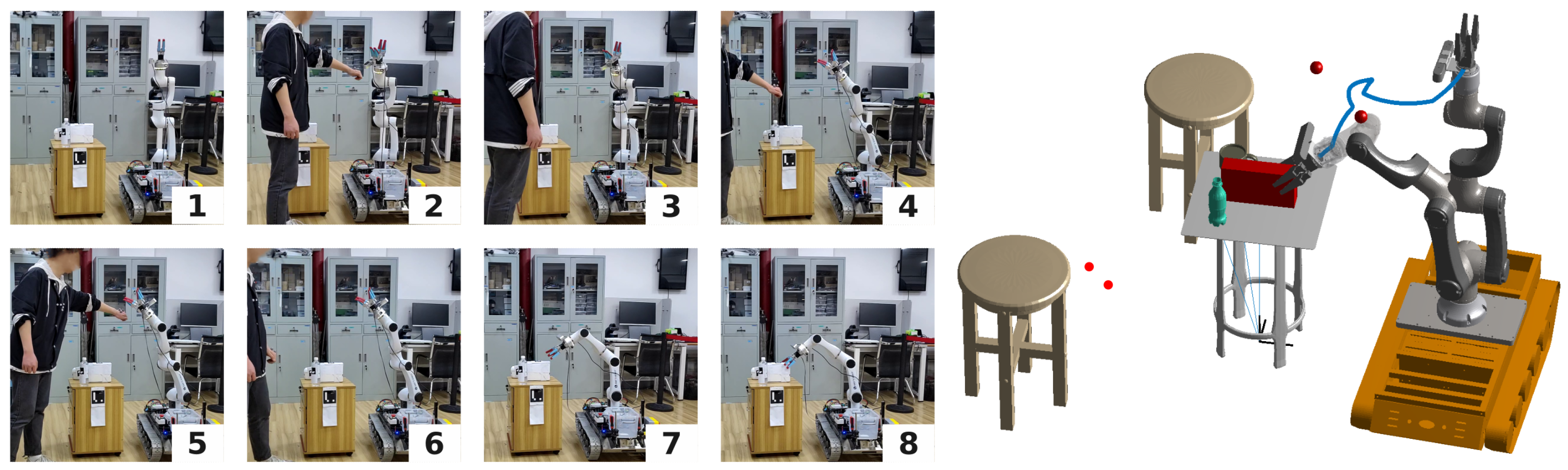
- We propose a collision detection strategy based on the proposed RobotSDF and verify the effectiveness and efficiency of the algorithm in the simulation and real manipulation experiments.
2. Literature Review
2.1. Geometry-Based Morphology Modeling
2.2. SDF-Based Morphology Modeling
3. Methodology
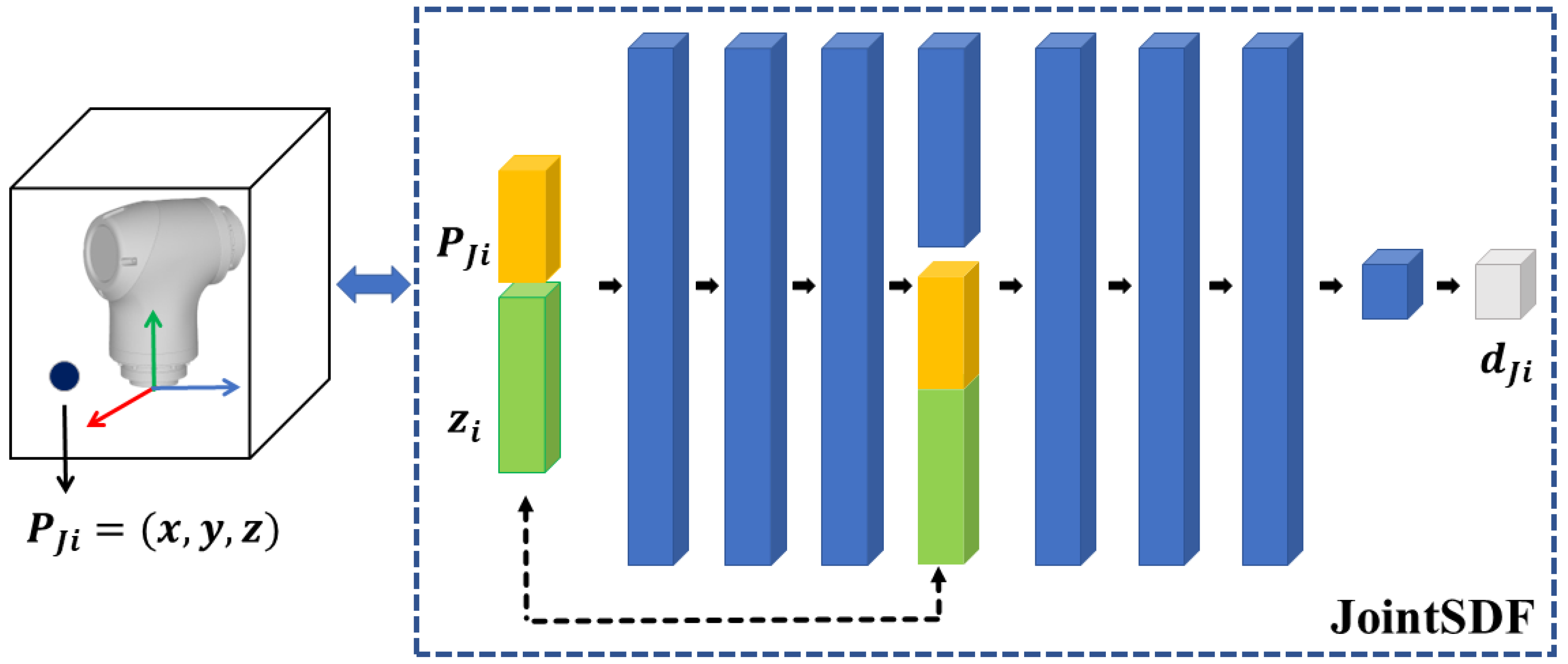
3.1. JointSDF
3.2. RobotSDF
3.3. Collision Detection Based on RobotSDF
4. Implementation Details
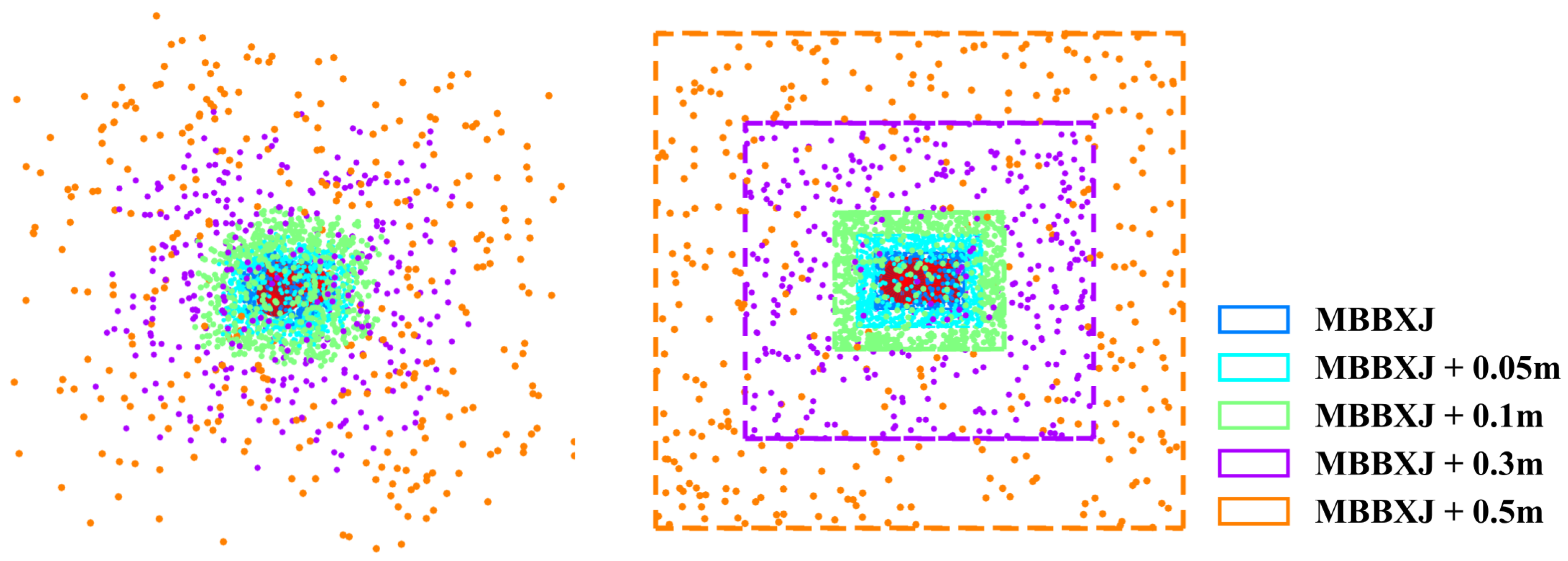
4.1. Data Preparation
4.2. Network Training
5. Experiments
5.1. Reconstruction Accuracy of RobotSDF
5.1.1. JointSDF Evaluation
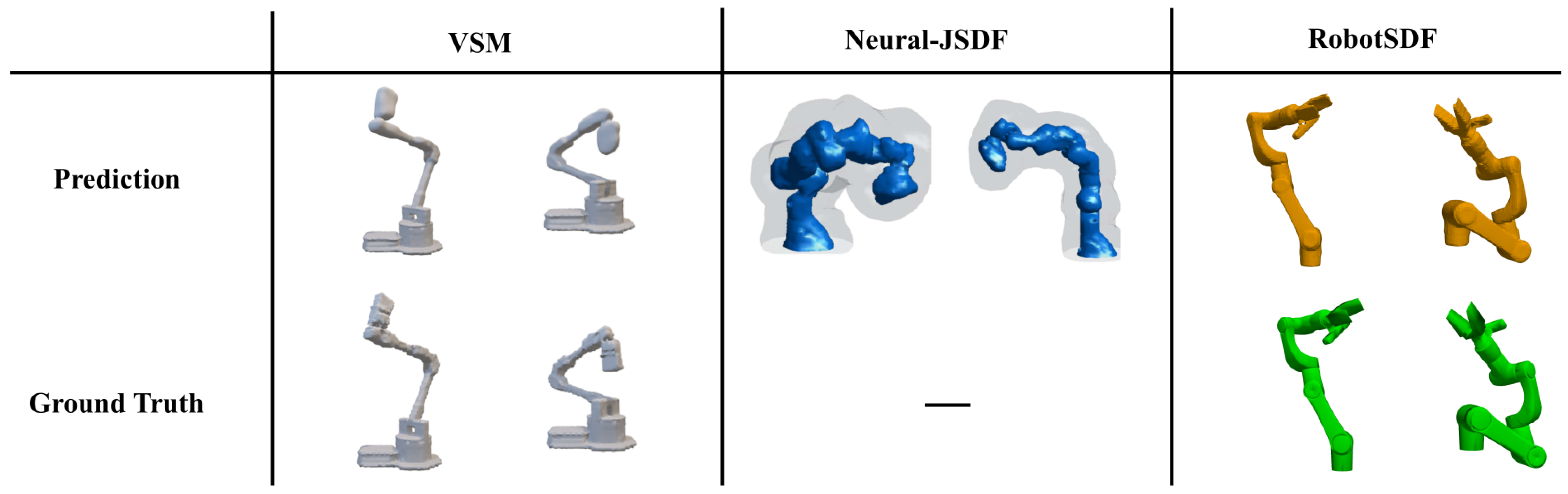
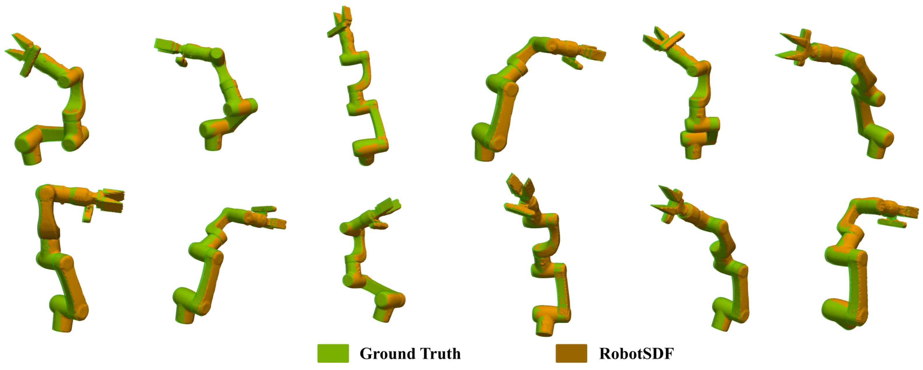
5.1.2. RobotSDF Evaluation
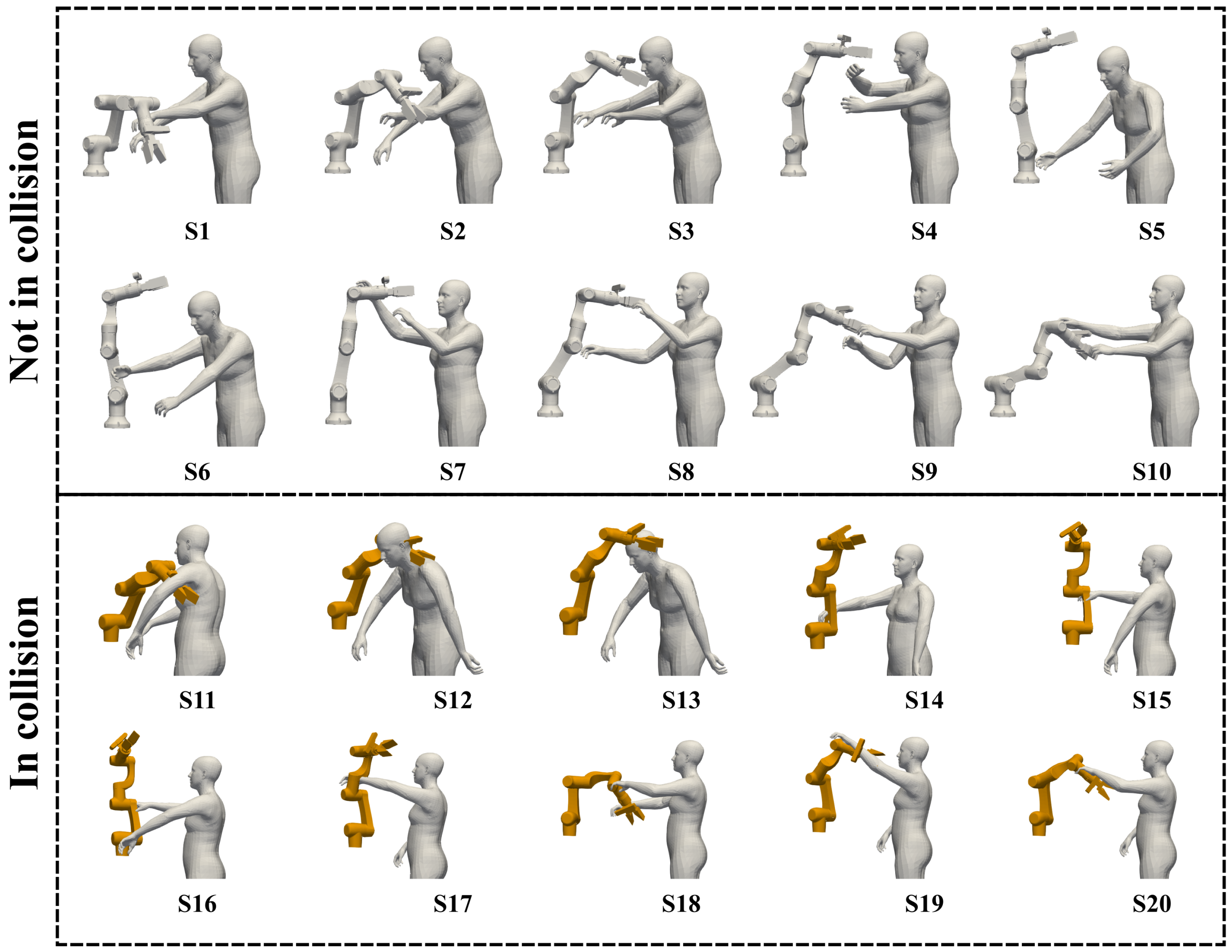
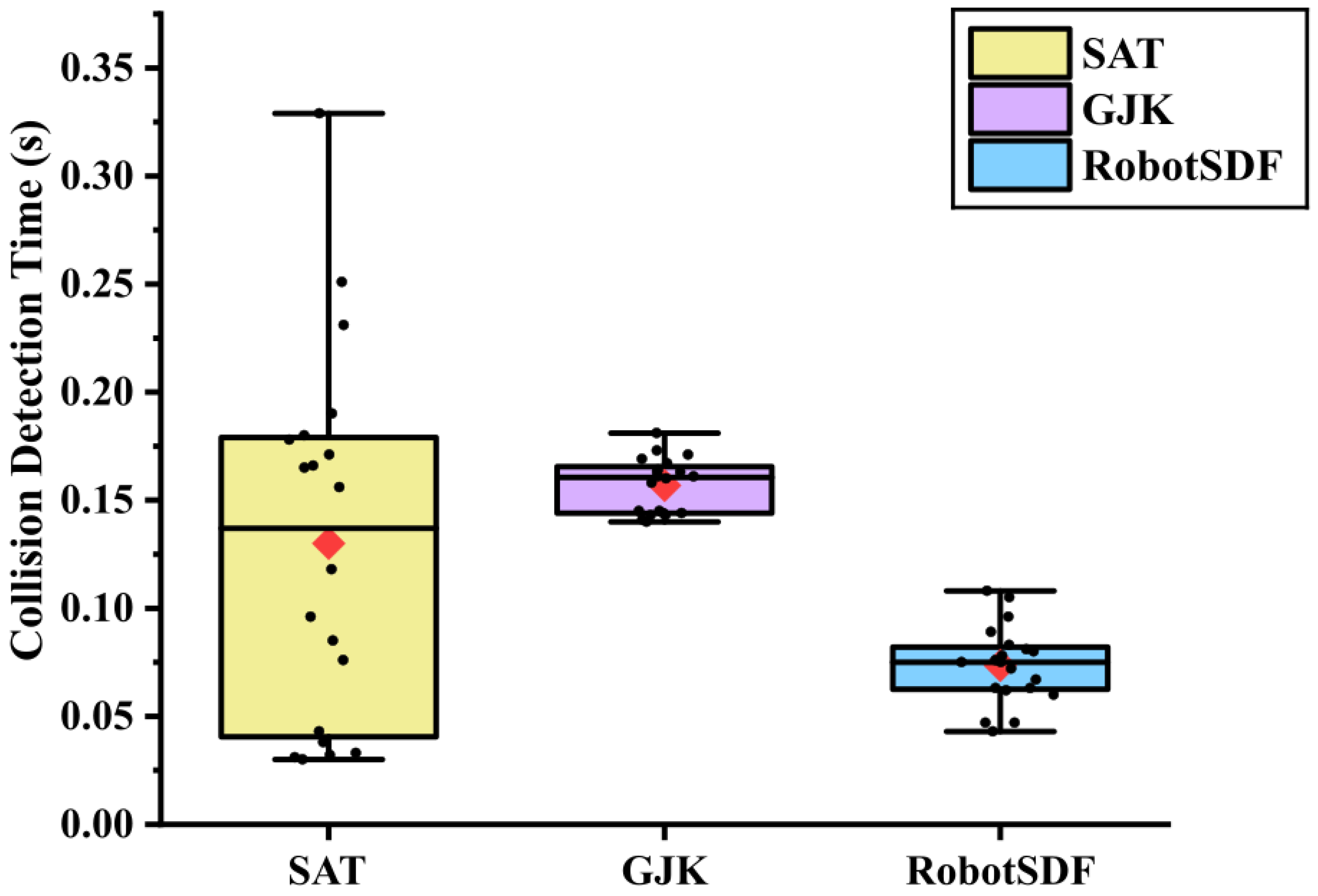
5.2. Collision Detection Evaluation
5.3. Adaptability Evaluation
6. Conclusions
Author Contributions
Funding
Institutional Review Board Statement
Informed Consent Statement
Data Availability Statement
Conflicts of Interest
References
- Ordoñez-Apraez, D.; Turrisi, G.; Kostic, V.; Martin, M.; Agudo, A.; Moreno-Noguer, F.; Pontil, M.; Semini, C.; Mastalli, C. Morphological symmetries in robotics. arXiv 2024, arXiv:2402.15552. [Google Scholar]
- Polverini, M.P.; Zanchettin, A.M.; Rocco, P. Real-time collision avoidance in human-robot interaction based on kinetostatic safety field. In Proceedings of the 2014 IEEE/RSJ International Conference on Intelligent Robots and Systems, Chicago, IL, USA, 14–18 September 2014; pp. 4136–4141. [Google Scholar]
- Dröder, K.; Bobka, P.; Germann, T.; Gabriel, F.; Dietrich, F. A machine learning-enhanced digital twin approach for human-robot-collaboration. Procedia CIRP 2018, 76, 187–192. [Google Scholar] [CrossRef]
- Matulis, M.; Harvey, C. A robot arm digital twin utilising reinforcement learning. Comput. Graph. 2021, 95, 106–114. [Google Scholar] [CrossRef]
- Bilberg, A.; Malik, A.A. Digital twin driven human–robot collaborative assembly. CIRP Ann. 2019, 68, 499–502. [Google Scholar] [CrossRef]
- Du, G.; Liang, Y.; Yao, G.; Li, C.; Murat, R.J.; Yuan, H. Active Collision Avoidance for Human-Manipulator Safety. IEEE Access 2020, 10, 16518–16529. [Google Scholar] [CrossRef]
- Liu, J.; Liu, R.; Shen, X.; Meng, L. Research on Obstacle Avoidance of Space Manipulators Based on Cylindrical Bounding Box Model. In Proceedings of the 2018 IEEE International Conference on Mechatronics and Automation (ICMA), Changchun, China, 5–8 August 2018; pp. 1926–1931. [Google Scholar] [CrossRef]
- Dai, P.; Hassan, M.; Sun, X.; Zhang, M.; Bian, Z.; Liu, D. A framework for multi-robot coverage analysis of large and complex structures. J. Intell. Manuf. 2022, 33, 1545–1560. [Google Scholar] [CrossRef]
- Ouyang, F.; Zhang, T. Octree-based Spherical hierarchical model for Collision detection. In Proceedings of the 10th World Congress on Intelligent Control and Automation, Beijing, China, 6–8 July 2012; pp. 3870–3875. [Google Scholar] [CrossRef]
- Pan, M.; Li, J.; Yang, X.; Wang, S.; Pan, L.; Su, T.; Wang, Y.; Yang, Q.; Liang, K. Collision risk assessment and automatic obstacle avoidance strategy for teleoperation robots. Comput. Ind. Eng. 2022, 169, 108275. [Google Scholar] [CrossRef]
- Safeea, M.; Neto, P.; Bearee, R. Efficient Calculation of Minimum Distance between Capsules and Its Use in Robotics. IEEE Access 2019, 7, 5368–5373. [Google Scholar] [CrossRef]
- Hermann, A.; Mauch, F.; Fischnaller, K.; Klemm, S.; Roennau, A.; Dillmann, R. Anticipate your surroundings: Predictive collision detection between dynamic obstacles and planned robot trajectories on the GPU. In Proceedings of the 2015 European Conference on Mobile Robots (ECMR), Lincoln, UK, 2–4 September 2015; pp. 1–8. [Google Scholar]
- Oleynikova, H.; Taylor, Z.; Fehr, M.; Siegwart, R.; Nieto, J. Voxblox: Incremental 3D Euclidean Signed Distance Fields for on-board MAV planning. In Proceedings of the 2017 IEEE/RSJ International Conference on Intelligent Robots and Systems (IROS), Vancouver, BC, Canada, 24–28 September 2017; pp. 1366–1373. [Google Scholar] [CrossRef]
- Martínez-Salvador, B.; Pérez-Francisco, M.; Del Pobil, A.P. Collision detection between robot arms and people. J. Intell. Robot. Syst. 2003, 38, 105–119. [Google Scholar] [CrossRef]
- Ivanou, M.; Mikhel, S.; Savin, S. Robot description formats and approaches: Review. In Proceedings of the 2021 International Conference “Nonlinearity, Information and Robotics“ (NIR), Innopolis, Russia, 26–29 August 2021; pp. 1–5. [Google Scholar]
- Camps, G.S.; Dyro, R.; Pavone, M.; Schwager, M. Learning Deep SDF Maps Online for Robot Navigation and Exploration. arXiv 2022, arXiv:2207.10782. [Google Scholar]
- Guo, F.; Wang, S.; Yue, B.; Wang, J. A deformable configuration planning framework for a parallel wheel-legged robot equipped with lidar. Sensors 2020, 20, 5614. [Google Scholar] [CrossRef] [PubMed]
- Sommer, C.; Sang, L.; Schubert, D.; Cremers, D. Gradient-SDF: A Semi-Implicit Surface Representation for 3D Reconstruction. In Proceedings of the IEEE/CVF Conference on Computer Vision and Pattern Recognition (CVPR), New Orleans, LA, USA, 18–24 June 2022; pp. 6280–6289. [Google Scholar]
- Boczko, E.M.; Young, T.R. The Signed Distance Function: A New Tool for Binary Classification. arXiv 2005, arXiv:cs/0511105. [Google Scholar]
- Park, J.J.; Florence, P.; Straub, J.; Newcombe, R.; Lovegrove, S. Deepsdf: Learning continuous signed distance functions for shape representation. In Proceedings of the IEEE/CVF Conference on Computer Vision and Pattern Recognition, Long Beach, CA, USA, 15–20 June 2019; pp. 165–174. [Google Scholar]
- Chen, B.; Kwiatkowski, R.; Vondrick, C.; Lipson, H. Fully body visual self-modeling of robot morphologies. Sci. Robot. 2022, 7, eabn1944. [Google Scholar] [CrossRef]
- Koptev, M.; Figueroa, N.; Billard, A. Neural joint space implicit signed distance functions for reactive robot manipulator control. IEEE Robot. Autom. Lett. 2022, 8, 480–487. [Google Scholar] [CrossRef]
- Lorensen, W.E.; Cline, H.E. Marching cubes: A high resolution 3D surface construction algorithm. In Proceedings of the SIGGRAPH ’87: 14th Annual Conference on Computer Graphics and Interactive Techniques, New York, NY, USA, 27–31 July 1987; pp. 163–169. [Google Scholar] [CrossRef]
- Zimmermann, S.; Busenhart, M.; Huber, S.; Poranne, R.; Coros, S. Differentiable collision avoidance using collision primitives. In Proceedings of the 2022 IEEE/RSJ International Conference on Intelligent Robots and Systems (IROS), Kyoto, Japan, 23–27 October 2022; pp. 8086–8093. [Google Scholar]
- Greenspan, M.; Burtnyk, N. Obstacle count independent real-time collision avoidance. In Proceedings of the IEEE International Conference on Robotics and Automation, Minneapolis, MN, USA, 22–28 April 1996; Volume 2, pp. 1073–1080. [Google Scholar]
- Steinbach, K.; Kuffner, J.; Asfour, T.; Dillmann, R. Efficient collision and self-collision detection for humanoids based on sphere trees hierarchies. In Proceedings of the 2006 6th IEEE-RAS International Conference on Humanoid Robots, Genova, Italy, 4–6 December 2006; pp. 560–566. [Google Scholar]
- Kot, T.; Bobovskỳ, Z.; Brandstötter, M.; Krys, V.; Virgala, I.; Novák, P. Finding optimal manipulator arm shapes to avoid collisions in a static environment. Appl. Sci. 2020, 11, 64. [Google Scholar] [CrossRef]
- Lei, M.; Wang, T.; Yao, C.; Liu, H.; Wang, Z.; Deng, Y. Real-time kinematics-based self-collision avoidance algorithm for dual-arm robots. Appl. Sci. 2020, 10, 5893. [Google Scholar] [CrossRef]
- Simoni, R.; Rodríguez, P.R.; Cieślak, P.; Youakim, D. A novel approach to obstacle avoidance for an I-AUV. In Proceedings of the 2018 IEEE/OES Autonomous Underwater Vehicle Workshop (AUV), Porto, Portugal, 6–9 November 2018; pp. 1–6. [Google Scholar]
- Bonci, A.; Cen Cheng, P.D.; Indri, M.; Nabissi, G.; Sibona, F. Human-robot perception in industrial environments: A survey. Sensors 2021, 21, 1571. [Google Scholar] [CrossRef] [PubMed]
- Lu, S.; Xu, Z.; Wang, B. Human-robot collision detection based on the improved camshift algorithm and bounding box. Int. J. Control Autom. Syst. 2022, 20, 3347–3360. [Google Scholar] [CrossRef]
- Safeea, M.; Neto, P.; Bearee, R. On-line collision avoidance for collaborative robot manipulators by adjusting off-line generated paths: An industrial use case. Robot. Auton. Syst. 2019, 119, 278–288. [Google Scholar] [CrossRef]
- Safeea, M.; Neto, P. Minimum distance calculation using laser scanner and IMUs for safe human-robot interaction. Robot. Comput.-Integr. Manuf. 2019, 58, 33–42. [Google Scholar] [CrossRef]
- Xu, J.; Liu, Z.; Yang, C.; Li, L.; Pei, Y. A pseudo-distance algorithm for collision detection of manipulators using convex-plane-polygons-based representation. Robot. Comput.-Integr. Manuf. 2020, 66, 101993. [Google Scholar] [CrossRef]
- Román-Ibáñez, V.; Pujol-López, F.A.; Mora-Mora, H.; Pertegal-Felices, M.L.; Jimeno-Morenilla, A. A Low-Cost Immersive Virtual Reality System for Teaching Robotic Manipulators Programming. Sustainability 2018, 10, 1102. [Google Scholar] [CrossRef]
- Duan, Y.; Zhu, H.; Wang, H.; Yi, L.; Nevatia, R.; Guibas, L.J. Curriculum deepsdf. In Proceedings of the Computer Vision–ECCV 2020: 16th European Conference, Glasgow, UK, 23–28 August 2020; Proceedings, Part VIII 16. Springer: Cham, Switzerland, 2020; pp. 51–67. [Google Scholar]
- Macklin, M.; Erleben, K.; Müller, M.; Chentanez, N.; Jeschke, S.; Corse, Z. Local optimization for robust signed distance field collision. Proc. Acm Comput. Graph. Interact. Tech. 2020, 3, 1–17. [Google Scholar] [CrossRef]
- Ortiz, J.; Clegg, A.; Dong, J.; Sucar, E.; Novotny, D.; Zollhoefer, M.; Mukadam, M. isdf: Real-time neural signed distance fields for robot perception. arXiv 2022, arXiv:2204.02296. [Google Scholar]
- Zhang, T.; Wang, J.; Xu, C.; Gao, A.; Gao, F. Continuous implicit sdf based any-shape robot trajectory optimization. In Proceedings of the 2023 IEEE/RSJ International Conference on Intelligent Robots and Systems (IROS), Detroit, MI, USA, 1–5 October 2023; pp. 282–289. [Google Scholar]
- Li, Y.; Zhang, Y.; Razmjoo, A.; Calinon, S. Representing robot geometry as distance fields: Applications to whole-body manipulation. In Proceedings of the 2024 IEEE International Conference on Robotics and Automation (ICRA), Yokohama, Japan, 13–17 May 2024; pp. 15351–15357. [Google Scholar]
- Finean, M.N.; Merkt, W.; Havoutis, I. Predicted composite signed-distance fields for real-time motion planning in dynamic environments. In Proceedings of the International Conference on Automated Planning and Scheduling, Guangzhou, China, 2–13 August 2021; Volume 31, pp. 616–624. [Google Scholar]
- Liu, P.; Zhang, K.; Tateo, D.; Jauhri, S.; Peters, J.; Chalvatzaki, G. Regularized deep signed distance fields for reactive motion generation. In Proceedings of the 2022 IEEE/RSJ International Conference on Intelligent Robots and Systems (IROS), Kyoto, Japan, 23–27 October 2022; pp. 6673–6680. [Google Scholar]
- Lee, M.H.; Liu, J.S. Fast Collision Detection for Robot Manipulator Path: An Approach Based on Implicit Neural Representation of Multiple Swept Volumes. In Proceedings of the 2023 International Conference on Advanced Robotics and Intelligent Systems (ARIS), Taipei, Taiwan, 30 August–1 September 2023; pp. 1–7. [Google Scholar]
- Li, Y.; Chi, X.; Razmjoo, A.; Calinon, S. Configuration Space Distance Fields for Manipulation Planning. arXiv 2024, arXiv:2406.01137. [Google Scholar]
- Gottschalk, S.; Lin, M.C.; Manocha, D. OBBTree: A hierarchical structure for rapid interference detection. In Proceedings of the 23rd Annual Conference on Computer Graphics and Interactive Techniques, New Orleans, LA, USA, 4–9 August 1996; pp. 171–180. [Google Scholar]
- Gilbert, E.G.; Johnson, D.W.; Keerthi, S.S. A fast procedure for computing the distance between complex objects in three-dimensional space. IEEE J. Robot. Autom. 1988, 4, 193–203. [Google Scholar] [CrossRef]
- Loper, M.; Mahmood, N.; Romero, J.; Pons-Moll, G.; Black, M.J. SMPL: A skinned multi-person linear model. In Seminal Graphics Papers: Pushing the Boundaries, Volume 2; Association for Computing Machinery: New York, NY, USA, 2023; pp. 851–866. [Google Scholar]


| Name | JointSDF1 | JointSDF2 | JointSDF3 | JointSDF4 | JointSDF5 | JointSDF6 |
|---|---|---|---|---|---|---|
| RMSE (std) (mm) | 8.11 (7.58) | 5.13 (3.17) | 6.53 (4.04) | 5.66 (4.05) | 6.31 (4.30) | 6.52 (4.57) |
| Robot Type | RMSE (mm) | Std (mm) | |
|---|---|---|---|
| RobotSDF (Ours) | Elfin E03 with Gripper | 6.38 | 4.62 |
| Neural-JSDF [22] | Franka Emika Panda | 10.40 | 7.80 |
| CDF [44] | Franka Emika Panda | 18.90 | 8.00 |
| S1 | S2 | S3 | S4 | S5 | S6 | S7 | S8 | S9 | S10 | |
| SAT | Y | N | Y | N | N | Y | N | N | N | Y |
| GJK | Y | N | N | N | N | N | N | N | N | N |
| RobotSDF | N | N | N | N | N | N | N | N | N | N |
| GT | N | N | N | N | N | N | N | N | N | N |
| S11 | S12 | S13 | S14 | S15 | S16 | S17 | S18 | S19 | S20 | |
| SAT | Y | Y | Y | Y | Y | Y | Y | Y | Y | Y |
| GJK | Y | Y | Y | Y | Y | Y | Y | Y | Y | Y |
| RobotSDF | Y | Y | Y | Y | Y | Y | Y | Y | Y | Y |
| GT | Y | Y | Y | Y | Y | Y | Y | Y | Y | Y |
Disclaimer/Publisher’s Note: The statements, opinions and data contained in all publications are solely those of the individual author(s) and contributor(s) and not of MDPI and/or the editor(s). MDPI and/or the editor(s) disclaim responsibility for any injury to people or property resulting from any ideas, methods, instructions or products referred to in the content. |
© 2024 by the authors. Licensee MDPI, Basel, Switzerland. This article is an open access article distributed under the terms and conditions of the Creative Commons Attribution (CC BY) license (https://creativecommons.org/licenses/by/4.0/).
Share and Cite
Yang, Y.; Liu, J.; Zhou, H.; Kwabena, A.R.; Zhong, Y.; Xie, Y. RobotSDF: Implicit Morphology Modeling for the Robotic Arm. Sensors 2024, 24, 5248. https://doi.org/10.3390/s24165248
Yang Y, Liu J, Zhou H, Kwabena AR, Zhong Y, Xie Y. RobotSDF: Implicit Morphology Modeling for the Robotic Arm. Sensors. 2024; 24(16):5248. https://doi.org/10.3390/s24165248
Chicago/Turabian StyleYang, Yusheng, Jiajia Liu, Hongpeng Zhou, Afimbo Reuben Kwabena, Yuqiao Zhong, and Yangmin Xie. 2024. "RobotSDF: Implicit Morphology Modeling for the Robotic Arm" Sensors 24, no. 16: 5248. https://doi.org/10.3390/s24165248