
High-Precision Positioning and Rotation Angle Estimation for a Target Pallet Based on BeiDou Navigation Satellite System and Vision


Abstract
1. Introduction
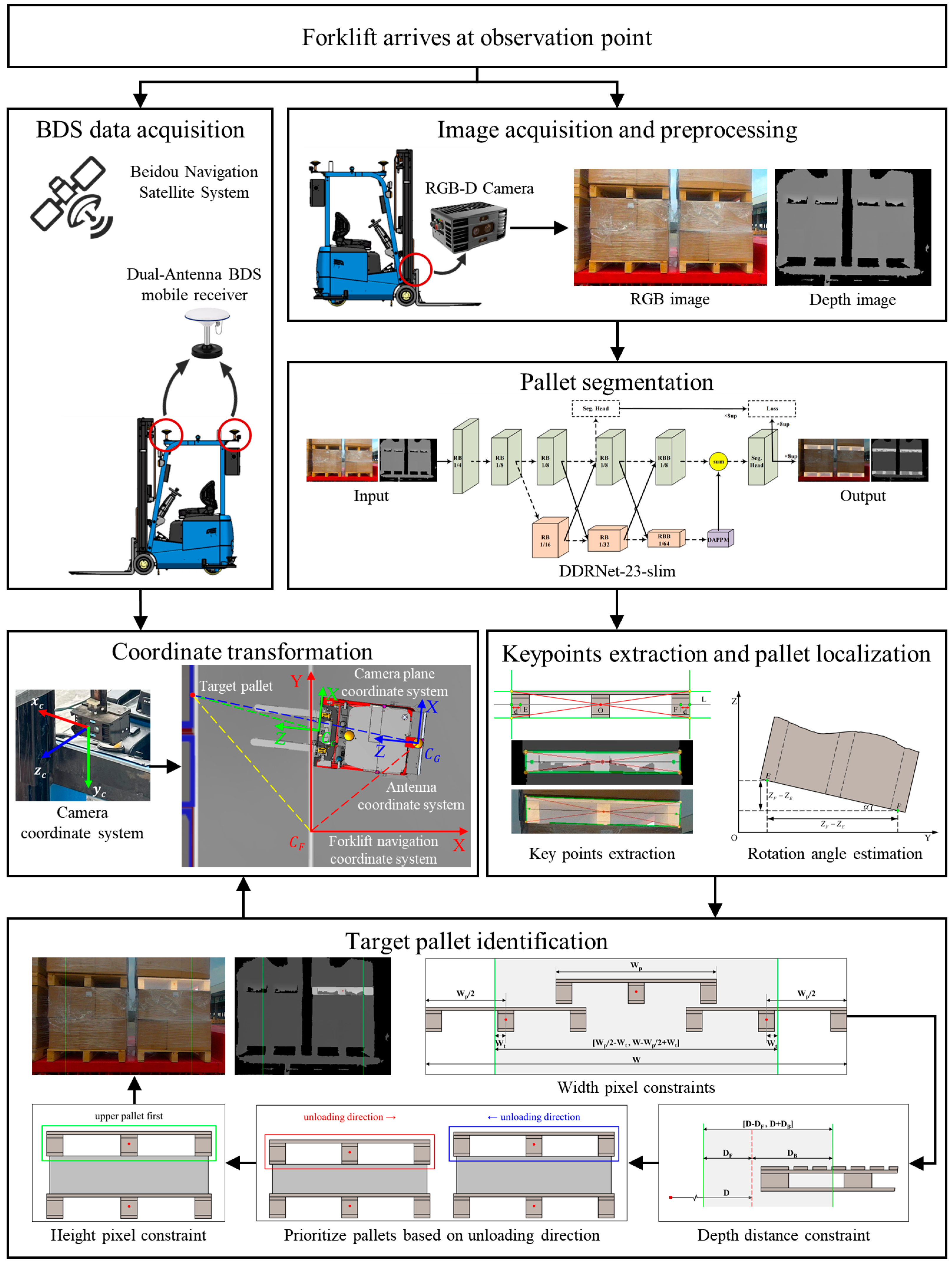
2. Method
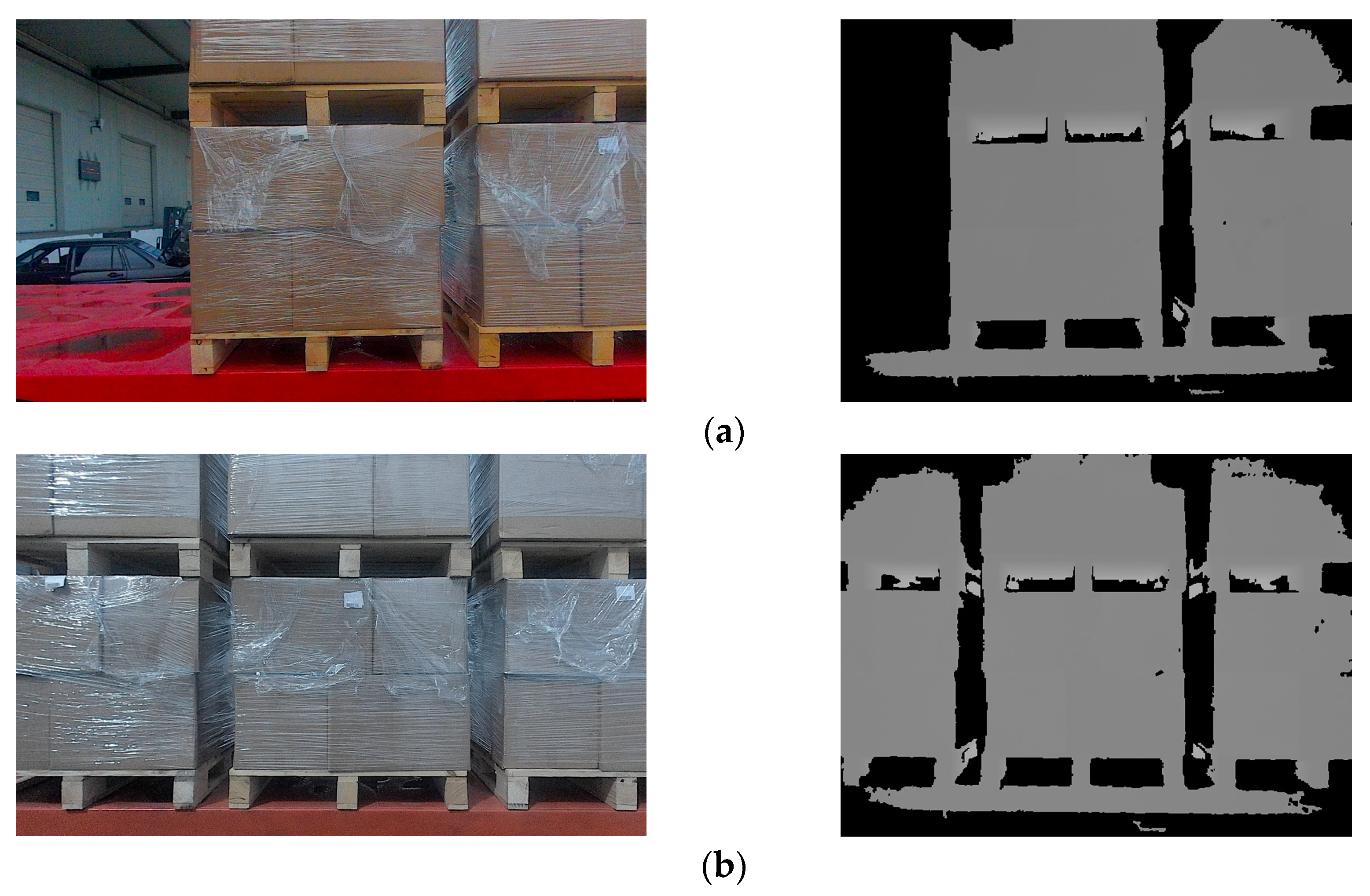
2.1. Image Acquisition and Preprocessing
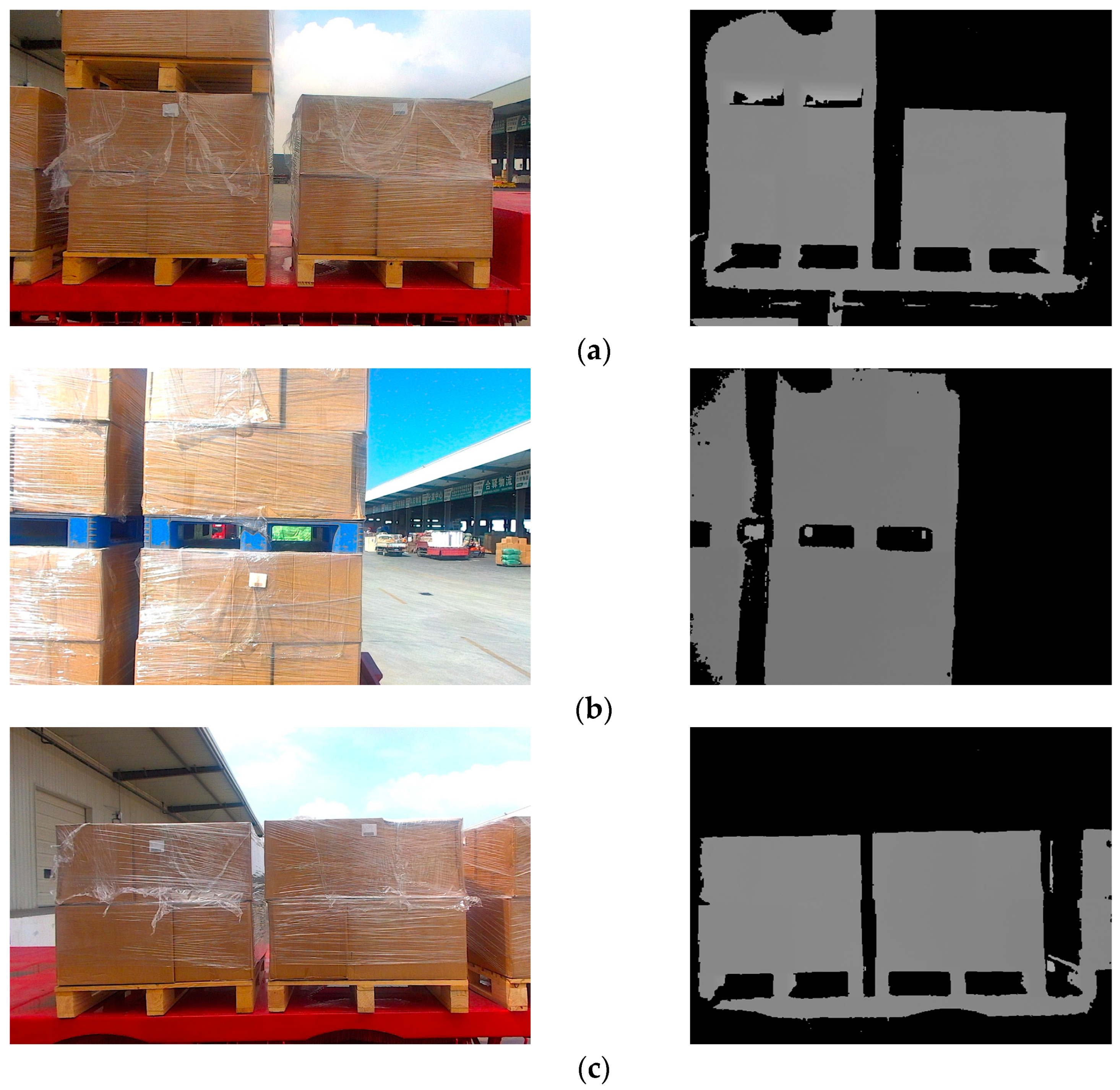
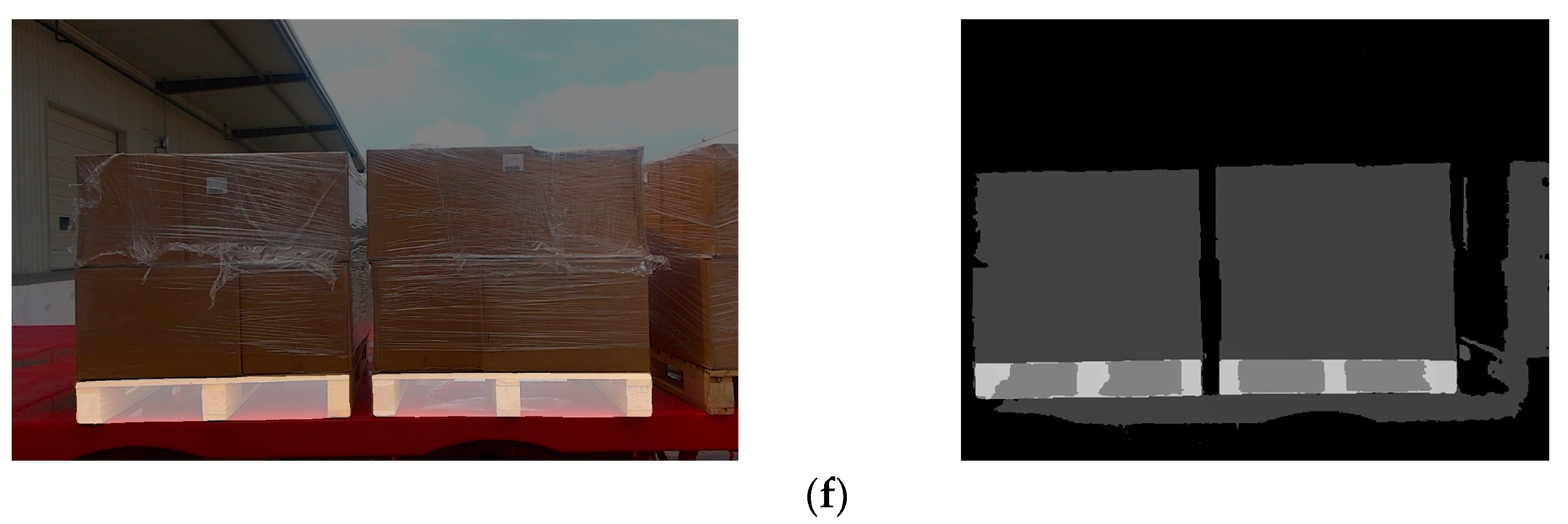
2.2. Pallet Segmentation
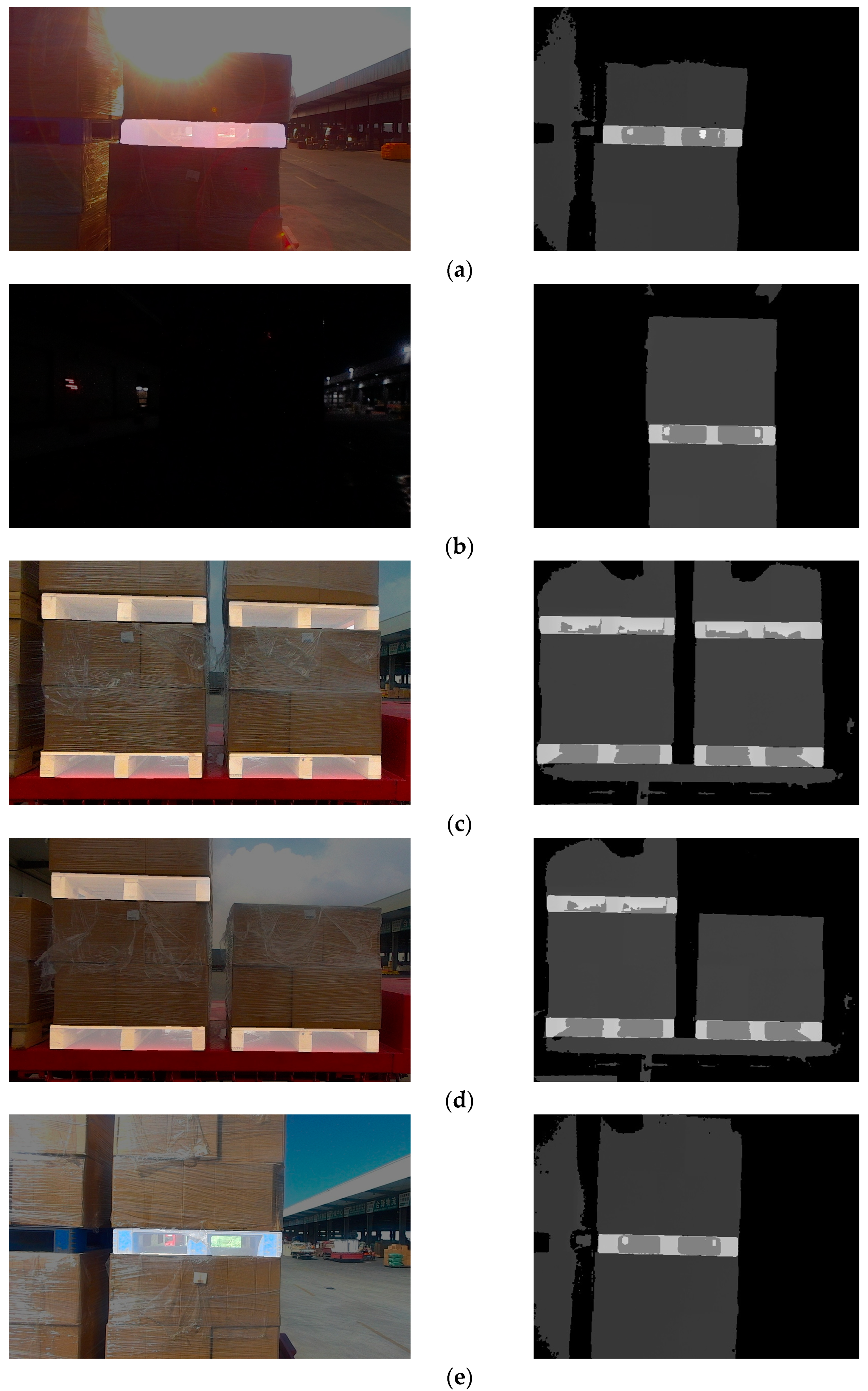
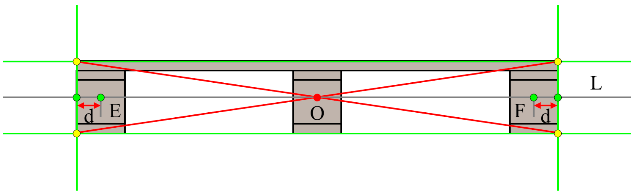
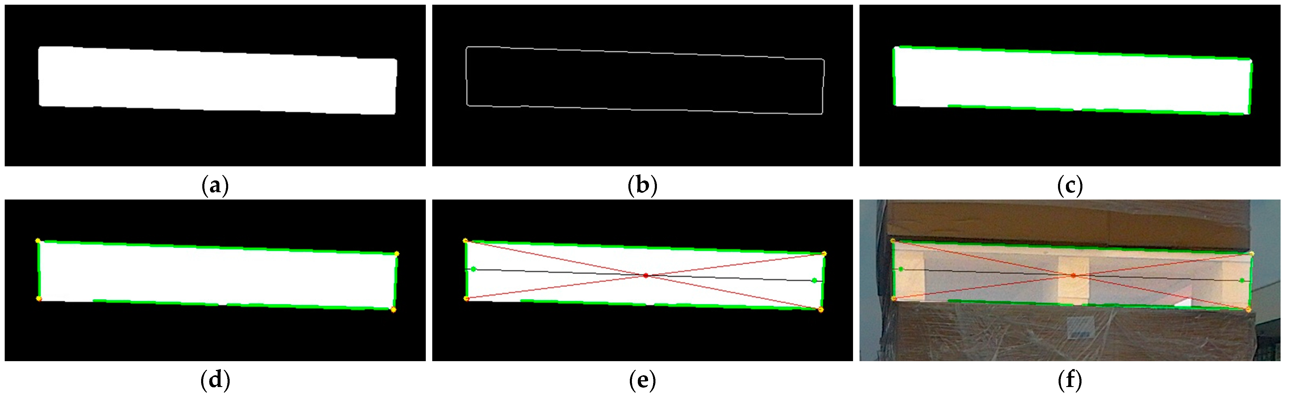
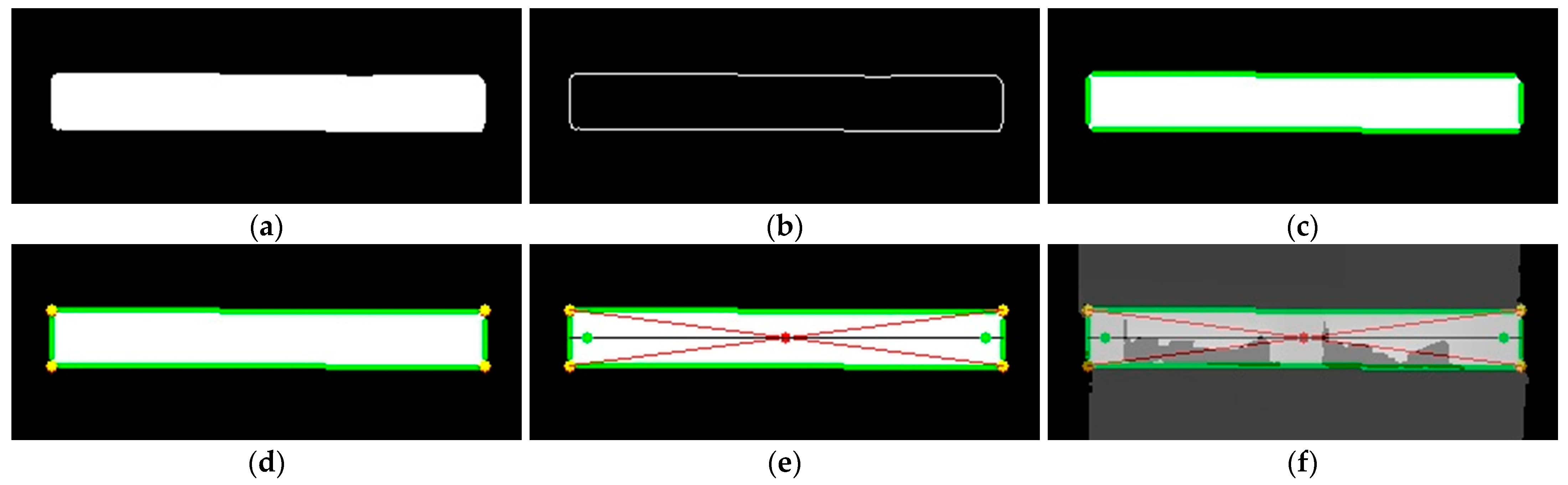
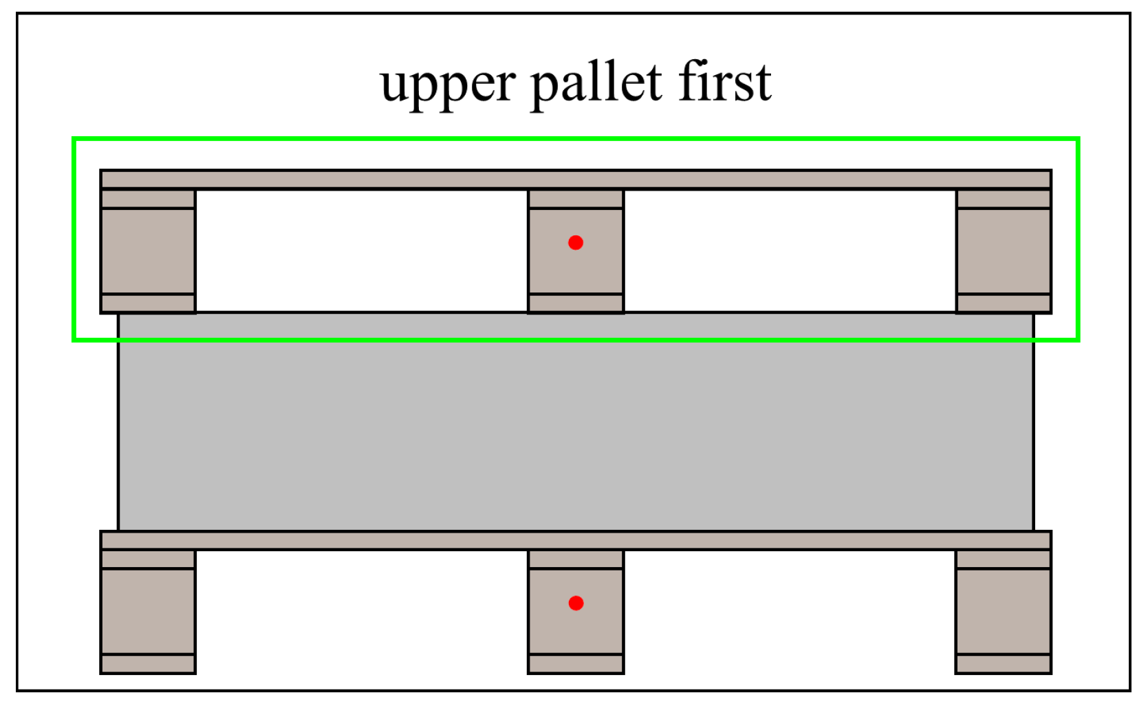
2.3. Keypoint Extraction and Pallet Localization
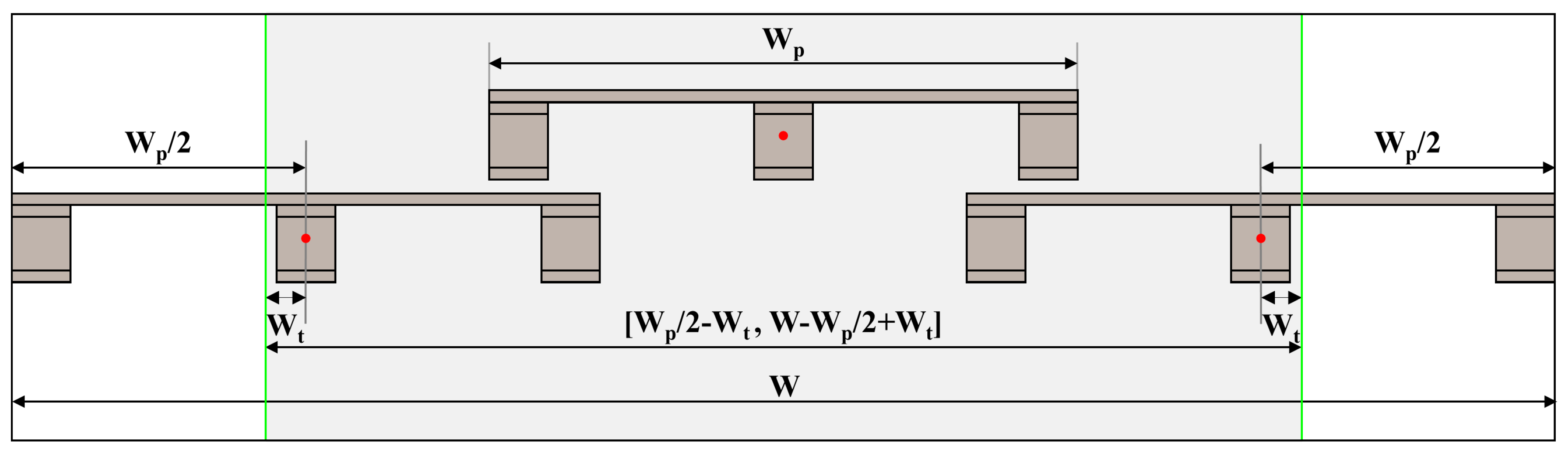
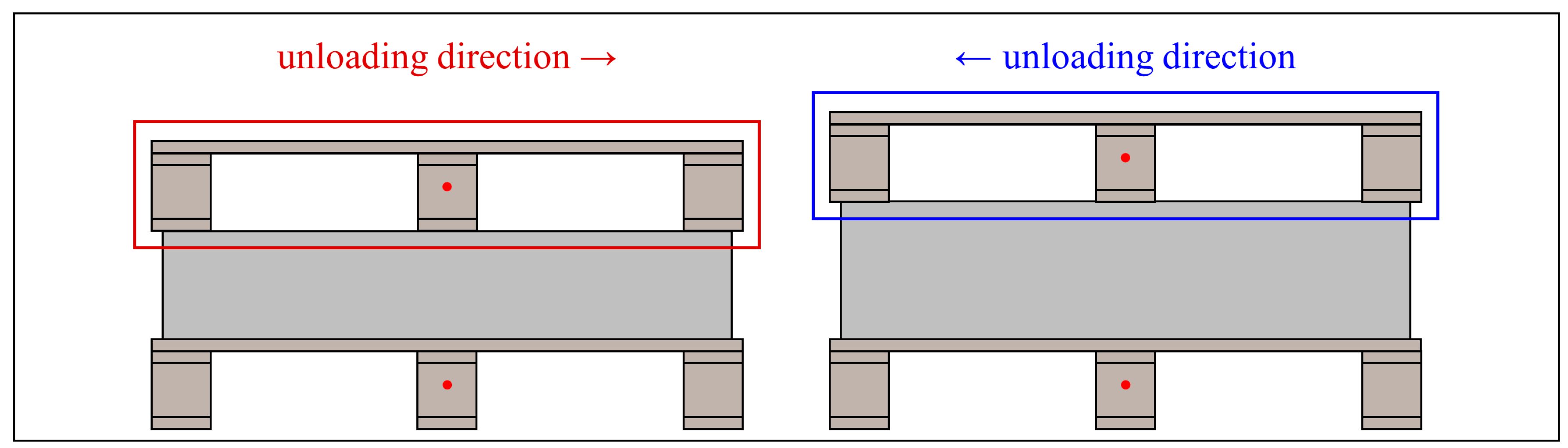
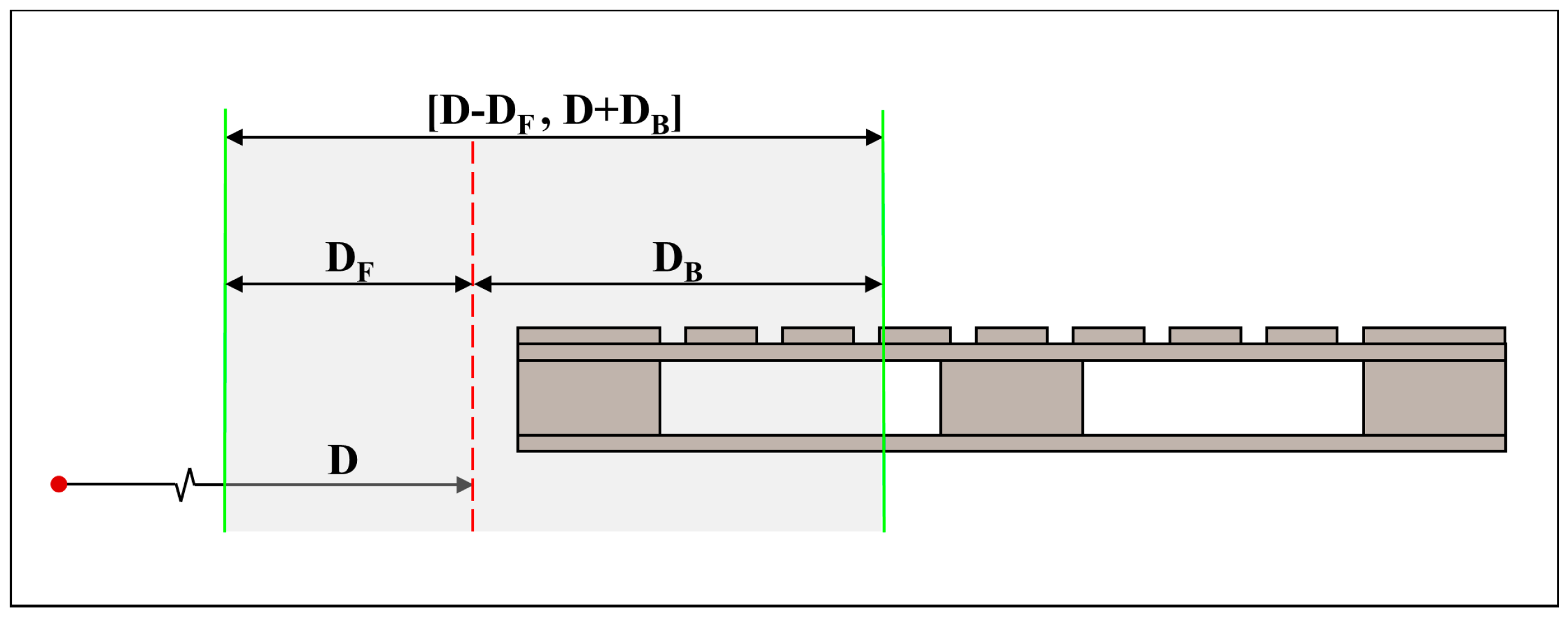
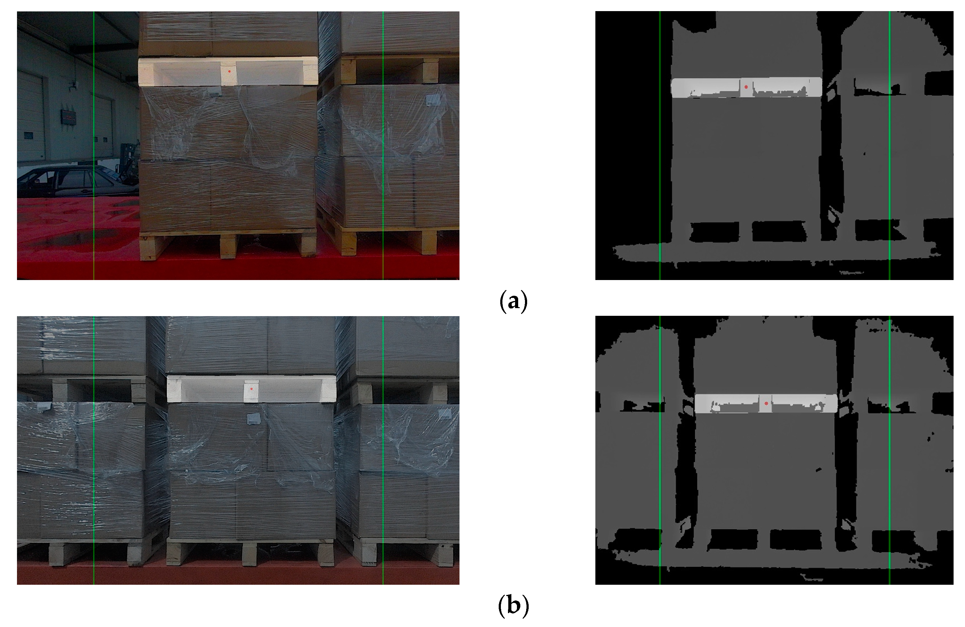
2.4. Target Pallet Identification
2.5. BDS Data Acquisition
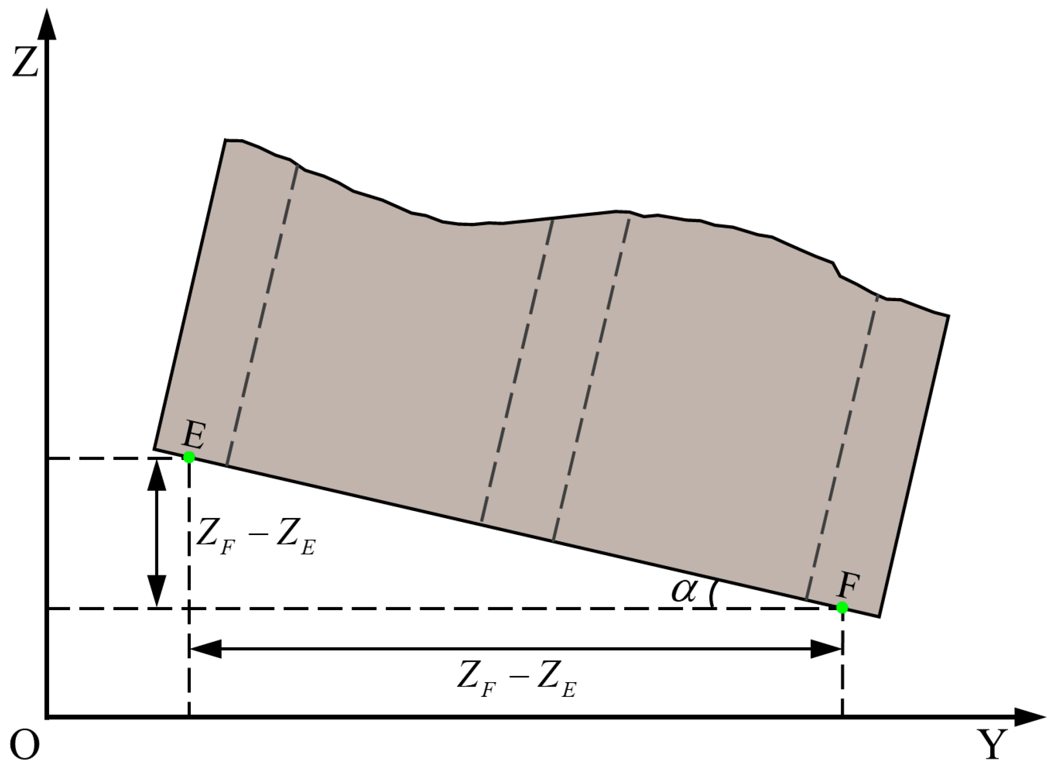
2.6. Coordinate Transformation
3. Experiments
3.1. Forklift and Sensor Selection
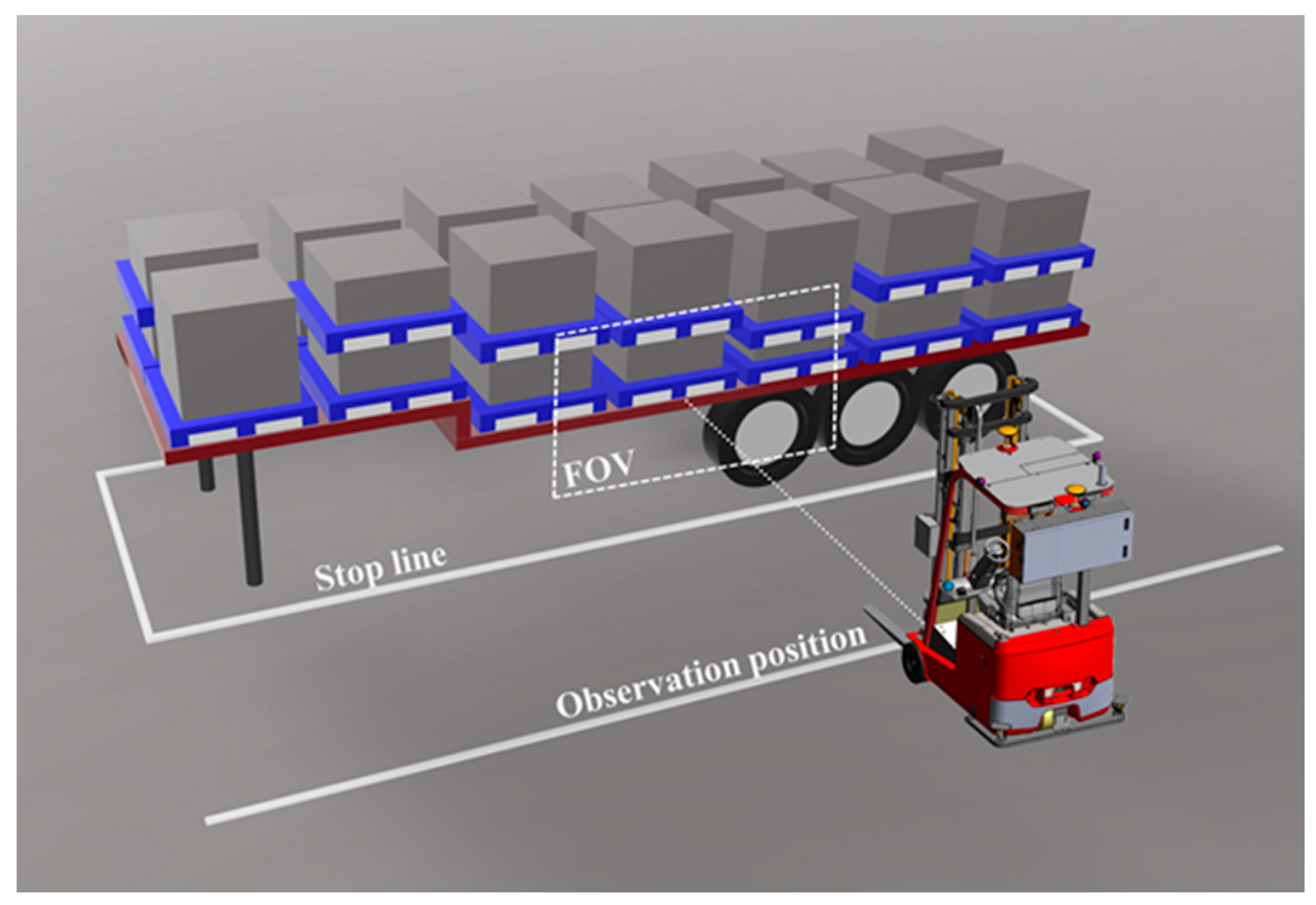
3.2. Experimental Site
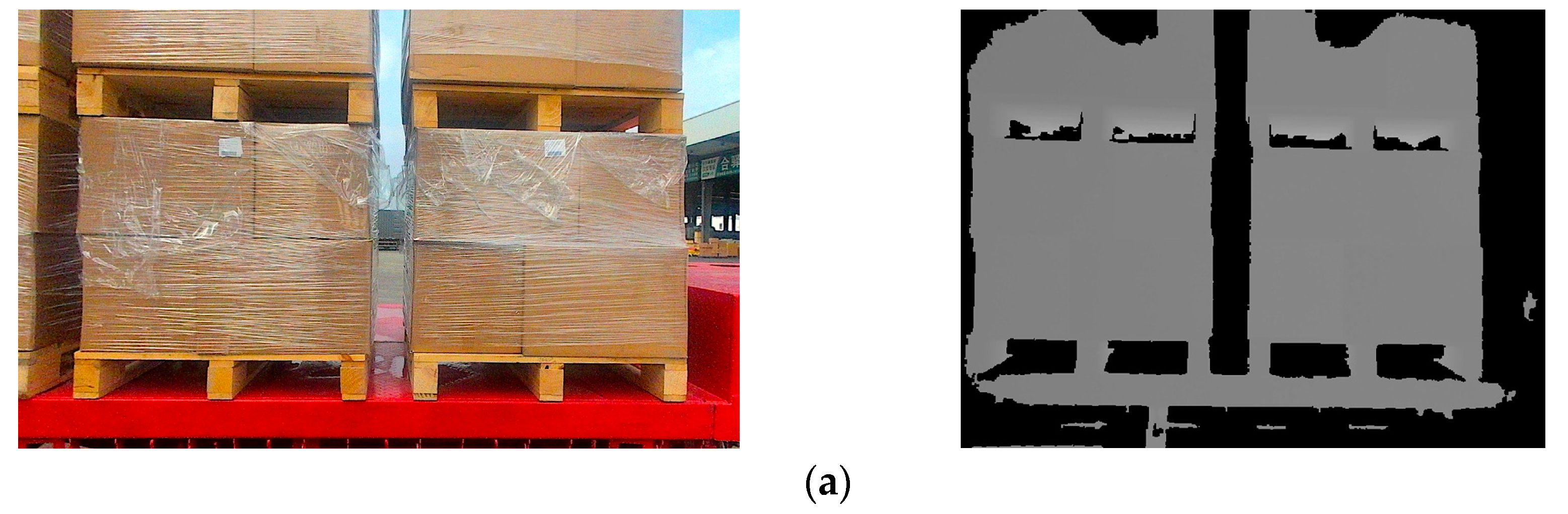
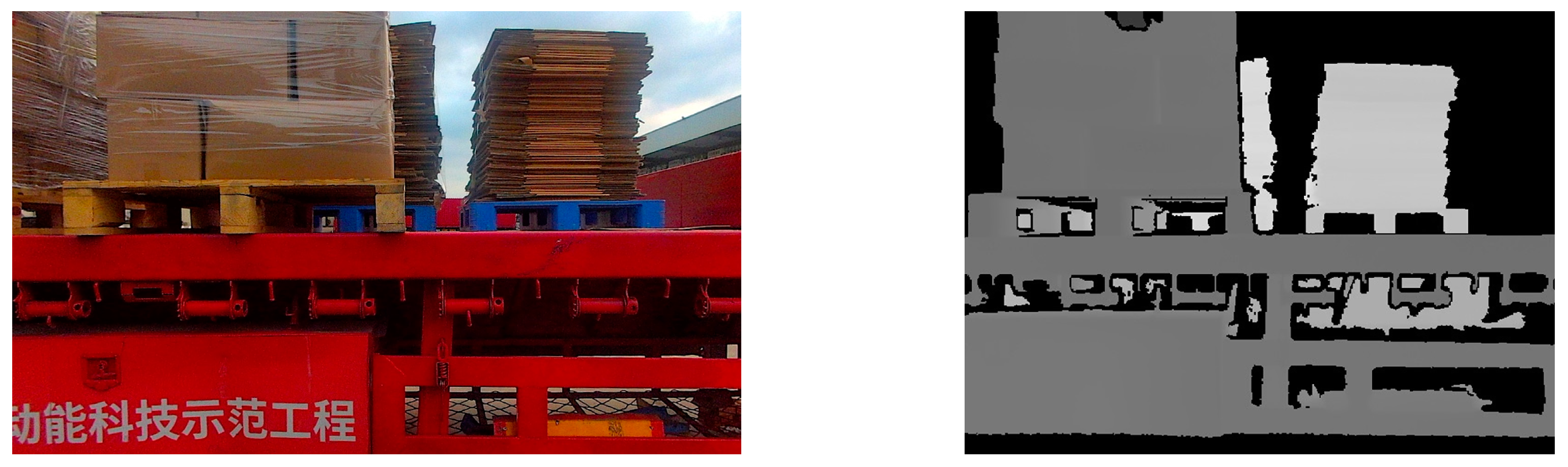
3.3. Pallet Image Segmentation Dataset
3.4. Parameter Setting
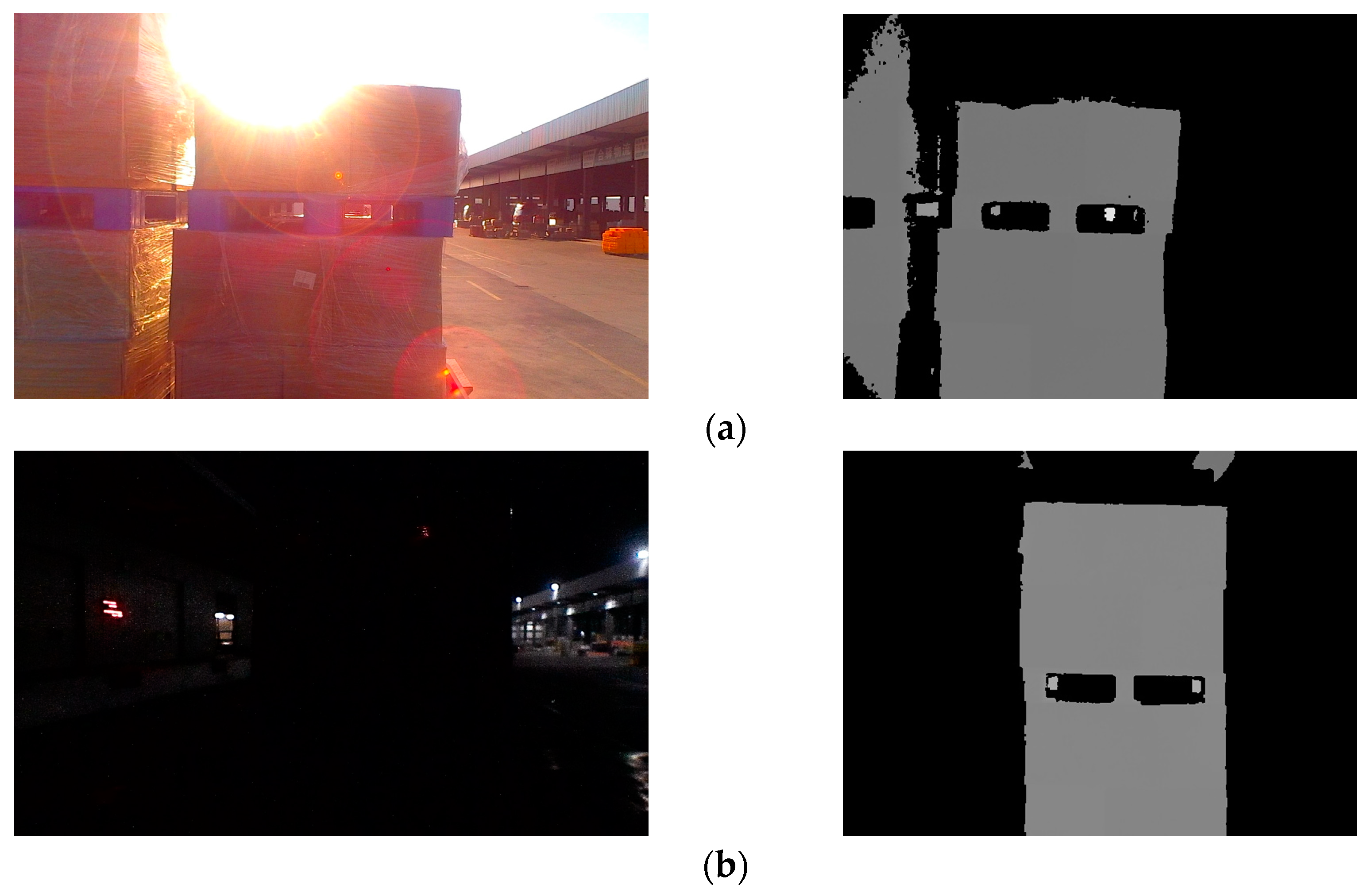
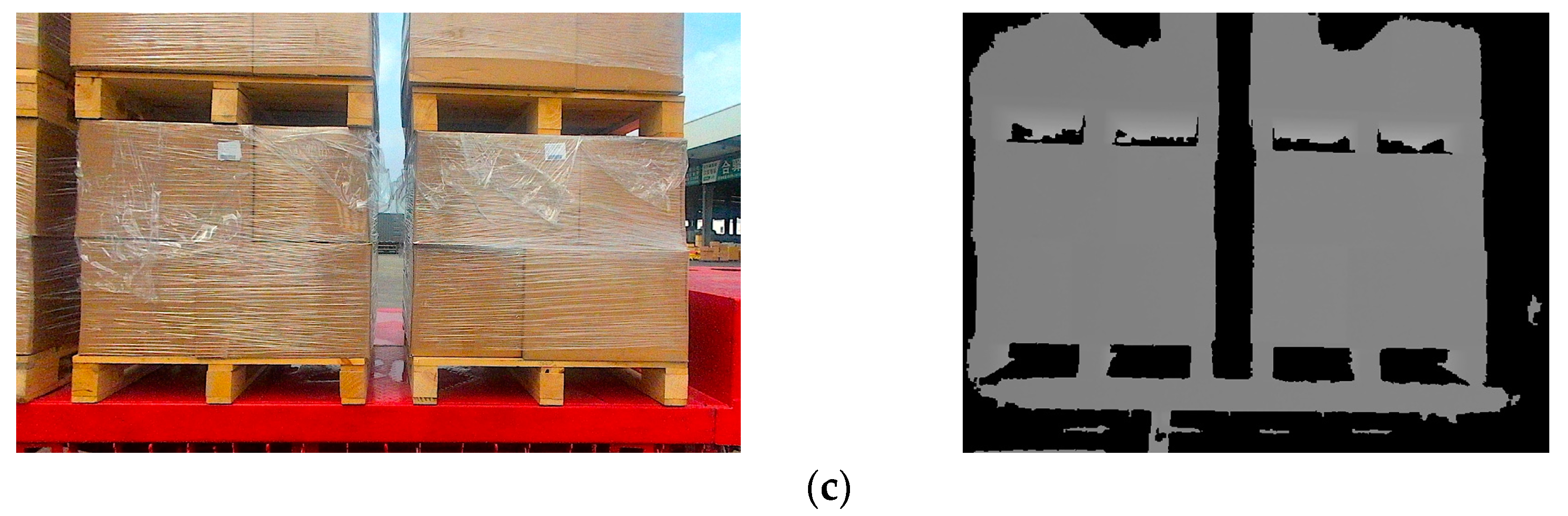
3.4.1. Preprocessing Parameter Selection
3.4.2. Keypoint Extraction Parameter Settings
3.4.3. Target Pallet Constraint Threshold Settings
4. Evaluation
5. Conclusions
6. Patents
Author Contributions
Funding
Institutional Review Board Statement
Informed Consent Statement
Data Availability Statement
Conflicts of Interest
References
- Hanson, R.; Agrawal, T.; Browne, M.; Johansson, M.; Andersson, D.; Stefansson, G.; Katsela, K. Challenges and requirements in the introduction of automated loading and unloading. In Proceedings of the 11th Swedish Transportation Research Conference, Lund, Sweden, 18–19 October 2022. [Google Scholar]
- Carlan, V.; Ceulemans, D.; van Hassel, E.; Derammelaere, S.; Vanelslander, T. Automation in cargo loading/unloading processes: Do unmanned loading technologies bring benefits when both purchase and operational cost are considered? J. Shipp. Trade 2023, 8, 20. [Google Scholar] [CrossRef]
- Syu, J.L.; Li, H.T.; Chiang, J.S.; Hsia, C.H.; Wu, P.H.; Hsieh, C.F.; Li, S.A. A computer vision assisted system for autonomous forklift vehicles in real factory environment. Multimed. Tools Appl. 2017, 76, 18387–18407. [Google Scholar] [CrossRef]
- Wu, W.H.; Yang, M.; Wang, B.; Wang, C.X. Pallet detection based on contour matching for warehouse robots. J. Shanghai Jiaotong Univ. 2019, 53, 197–202. [Google Scholar] [CrossRef]
- Cui, G.Z.; Lu, L.S.; He, Z.D.; Yao, L.N.; Yang, C.X.; Huang, B.Y.; Hu, Z.H. A robust autonomous mobile forklift pallet recognition. In Proceedings of the 2010 2nd International Asia Conference on Informatics in Control, Automation and Robotics (CAR 2010), Wuhan, China, 6–7 March 2010. [Google Scholar] [CrossRef]
- Byun, S.; Kim, M. Real-time positioning and orienting of pallets based on monocular vision. In Proceedings of the 2008 20th IEEE International Conference on Tools with Artificial Intelligence, Dayton, OH, USA, 3–5 November 2008. [Google Scholar] [CrossRef]
- Chen, G.; Peng, R.; Wang, Z.; Zhao, W. Pallet recognition and localization method for vision guided forklift. In Proceedings of the 2012 8th International Conference on Wireless Communications, Networking and Mobile Computing, Shanghai, China, 21–23 September 2012. [Google Scholar] [CrossRef]
- Jia, F.; Tao, Z.; Wang, F. Wooden pallet image segmentation based on Otsu and marker watershed. In Proceedings of the 2021 International Conference on Computer, Communication, Control, Automation and Robotics (CCCAR 2021), Shanghai, China, 29–30 March 2021. [Google Scholar] [CrossRef]
- Seelinger, M.; Yoder, J.D. Automatic visual guidance of a forklift engaging a pallet. Robot. Auton. Syst. 2006, 54, 1026–1038. [Google Scholar] [CrossRef]
- Kesuma, E.S.; Rusmin, P.H.; Maharani, D.A. Pallet detection and distance estimation with YOLO and fiducial marker algorithm in industrial forklift robot. In Proceedings of the 2023 International Conference on Artificial Intelligence in Information and Communication (ICAIIC), Bali, Indonesia, 20–23 February 2023. [Google Scholar] [CrossRef]
- Li, T.; Huang, B.; Li, C.; Huang, M. Application of convolution neural network object detection algorithm in logistics warehouse. J. Eng. 2019, 2019, 9053–9058. [Google Scholar] [CrossRef]
- Zaccaria, M.; Monica, R.; Aleotti, J. A comparison of deep learning models for pallet detection in industrial warehouses. In Proceedings of the 2020 IEEE 16th International Conference on Intelligent Computer Communication and Processing (ICCP), Cluj-Napoca, Romania, 3–5 September 2020. [Google Scholar] [CrossRef]
- Kirci, S.; Atali, G. EuroPallet Detection with RGB-D Camera Based on Deep Learning. Eur. J. Res. Dev. 2023, 3, 55–65. [Google Scholar] [CrossRef]
- Mok, C.; Baek, I.; Cho, Y.S.; Kim, Y.; Kim, S.B. Pallet Recognition with Multi-Task Learning for Automated Guided Vehicles. Appl. Sci. 2021, 11, 11808. [Google Scholar] [CrossRef]
- Molter, B.; Fottner, J. Real-time pallet localization with 3d camera technology for forklifts in logistic environments. In Proceedings of the 2018 IEEE International Conference on Service Operations and Logistics, and Informatics (SOLI), Singapore, 31 July–2 August 2018. [Google Scholar] [CrossRef]
- Xiao, J.; Lu, H.; Zhang, L.; Zhang, J. Pallet recognition and localization using an rgb-d camera. Int. J. Adv. Robot. Syst. 2017, 14, 1729881417737799. [Google Scholar] [CrossRef]
- Shao, Y.; Fan, Z.; Zhu, B.; Zhou, M.; Chen, Z.; Lu, J. A Novel Pallet Detection Method for Automated Guided Vehicles Based on Point Cloud Data. Sensors 2022, 22, 8019. [Google Scholar] [CrossRef] [PubMed]
- Shao, Y.; Fan, Z.; Zhu, B.; Lu, J.; Lang, Y. A Point Cloud Data-Driven Pallet Pose Estimation Method Using an Active Binocular Vision Sensor. Sensors 2023, 23, 1217. [Google Scholar] [CrossRef] [PubMed]
- Li, Y.Y.; Chen, X.H.; Ding, G.Y.; Wang, S.; Xu, W.C.; Sun, B.B.; Song, Q. Pallet detection and localization with RGB image and depth data using deep learning techniques. In Proceedings of the 2021 6th International Conference on Automation, Control and Robotics Engineering (CACRE), Dalian, China, 15–17 July 2021. [Google Scholar] [CrossRef]
- Iinuma, R.; Kojima, Y.; Onoyama, H.; Fukao, T.; Hattori, S.; Nonogaki, Y. Pallet handling system with an autonomous forklift for outdoor fields. J. Robot. Mechatron. 2020, 32, 1071–1079. [Google Scholar] [CrossRef]
- Iinuma, R.; Hori, Y.; Onoyama, H.; Fukao, T.; Kubo, Y. Pallet detection and estimation for fork insertion with rgb-d camera. In Proceedings of the 2021 IEEE International Conference on Mechatronics and Automation (ICMA), Takamatsu, Japan, 8–11 August 2021. [Google Scholar] [CrossRef]
- Rocha, E.D.S.; Chevtchenko, S.F.; Cambuim, L.F.; Macieira, R.M. Optimized Pallet Localization Using RGB-D Camera and Deep Learning Models. In Proceedings of the 2023 IEEE 19th International Conference on Intelligent Computer Communication and Processing (ICCP), Cluj-Napoca, Romania, 26–28 October 2023. [Google Scholar] [CrossRef]
- Zhao, J.; Li, B.; Wei, X.; Lu, H.; Lü, E.; Zhou, X. Recognition and Location Algorithm for Pallets in Warehouses Using RGB-D Sensor. Appl. Sci. 2022, 12, 10331. [Google Scholar] [CrossRef]
- Pan, H.; Hong, Y.; Sun, W.; Jia, Y. Deep dual-resolution networks for real-time and accurate semantic segmentation of traffic scenes. IEEE Trans. Intell. Transp. Syst. 2022, 24, 3448–3460. [Google Scholar] [CrossRef]
- Galamhos, C.; Matas, J.; Kittler, J. Progressive probabilistic Hough transform for line detection. In Proceedings of the 1999 IEEE Computer Society Conference on Computer Vision and Pattern Recognition (Cat. No PR00149), Fort Collins, CO, USA, 23–25 June 1999. [Google Scholar] [CrossRef]
- MacQueen, J. Some methods for classification and analysis of multivariate observations. In Proceedings of the Fifth Berkeley Symposium on Mathematical Statistics and Probability, Berkeley, CA, USA, 21 June–18 July 1965 and 27 December 1965–7 January 1966. [Google Scholar]
- Zhang, P.; Xu, C.; Hu, C.; Chen, Y. Coordinate transformations in satellite navigation systems. In Proceedings of the 2011 International Conference on Electronic Engineering, Communication and Management (EECM 2011), Beijing, China, 24–25 December 2011. [Google Scholar] [CrossRef]
- Kuna, D.; Santhosh, N.; Perumalla, N.K. Preliminary analysis of standalone Galileo and NavIC in the context of positioning performance for low latitude region. Procedia Comput. Sci. 2020, 171, 225–234. [Google Scholar] [CrossRef]


| Stage | Output | DDRNet-23-Slim | |
|---|---|---|---|
| conv1 | 112 × 112 | 3 × 3, 32, stride 2 | |
| conv2 | 56 × 56 | 3 × 3, 32, stride 2 | |
| conv3 | 28 × 28 | ||
| conv4 | 14 × 14, 28 × 28 | ||
| Bilateral fusion | |||
| conv5_1 | 7 × 7, 28 × 28 | ||
| Bilateral fusion | |||
| conv5_2 | 7 × 7 | High-to-low fusion | |
| 1 × 1, 1024 | |||
| 1 × 1 | 7 × 7 global average pool | ||
| 1000-d fc, softmax | |||
| Number | Material | Color | Dimensions (W × L × H) mm | Diagram |
|---|---|---|---|---|
| 1 | Wood | Wooden | 1000 × 1200 × 150 | 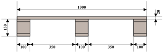 |
| 2 | Plastic | Blue | 1000 × 1200 × 150 | 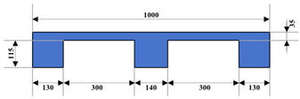 |
| Serial Number | RGB Images | Image Segmentation Results | Keypoint 1 Recognition Results | Target Pallet Identification Results |
|---|---|---|---|---|
| 1 |  |  |  |  |
| 2 |  |  |  | 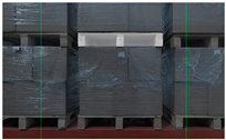 |
| 3 | 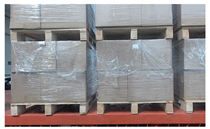 |  | 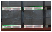 |  |
| Serial Number | Depth Images | Image Segmentation Results | Keypoint 1 Recognition Results | Target Pallet Identification Results |
|---|---|---|---|---|
| 1 |  |  |  |  |
| 2 |  |  |  | 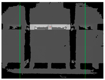 |
| 3 |  |  | 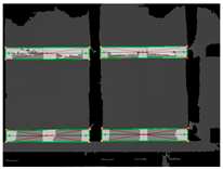 |  |
| Serial Number | Degrees of Freedom | Error (mm/°) | |||
|---|---|---|---|---|---|
| 1 | X | 9.682 | 16.218 | 12.440 | 2.160 |
| Y | 11.826 | 16.996 | 14.669 | 1.695 | |
| Z | 10.405 | 15.041 | 13.088 | 1.556 | |
| Angle | 0.012 | 0.318 | 0.182 | 0.200 | |
| 2 | X | 8.172 | 14.183 | 10.964 | 2.004 |
| Y | 10.537 | 16.543 | 13.198 | 1.771 | |
| Z | 10.313 | 15.679 | 13.061 | 1.750 | |
| Angle | 0.015 | 0.336 | 0.172 | 0.190 | |
| 3 | X | 11.157 | 15.426 | 13.088 | 1.207 |
| Y | 10.496 | 15.373 | 13.156 | 1.678 | |
| Z | 11.507 | 17.319 | 14.245 | 1.835 | |
| Angle | 0.016 | 0.313 | 0.180 | 0.198 | |
| Serial Number | Degrees of Freedom | Error (mm/°) | |||
|---|---|---|---|---|---|
| 1 | X | 13.121 | 19.679 | 15.882 | 1.878 |
| Y | 13.165 | 19.579 | 17.093 | 1.784 | |
| Z | 11.150 | 15.777 | 13.753 | 1.532 | |
| Angle | 0.018 | 0.349 | 0.185 | 0.211 | |
| 2 | X | 10.091 | 15.830 | 13.665 | 1.671 |
| Y | 12.549 | 19.914 | 16.645 | 1.815 | |
| Z | 10.993 | 16.960 | 14.085 | 2.033 | |
| Angle | 0.019 | 0.364 | 0.169 | 0.181 | |
| 3 | X | 12.972 | 18.388 | 15.603 | 1.723 |
| Y | 13.830 | 19.766 | 17.579 | 1.991 | |
| Z | 12.387 | 18.135 | 15.854 | 1.764 | |
| Angle | 0.007 | 0.358 | 0.177 | 0.206 | |
Disclaimer/Publisher’s Note: The statements, opinions and data contained in all publications are solely those of the individual author(s) and contributor(s) and not of MDPI and/or the editor(s). MDPI and/or the editor(s) disclaim responsibility for any injury to people or property resulting from any ideas, methods, instructions or products referred to in the content. |
© 2024 by the authors. Licensee MDPI, Basel, Switzerland. This article is an open access article distributed under the terms and conditions of the Creative Commons Attribution (CC BY) license (https://creativecommons.org/licenses/by/4.0/).
Share and Cite
Meng, D.; Ren, Y.; Yu, X.; Yin, X.; Wang, W.; Men, J. High-Precision Positioning and Rotation Angle Estimation for a Target Pallet Based on BeiDou Navigation Satellite System and Vision. Sensors 2024, 24, 5330. https://doi.org/10.3390/s24165330
Meng D, Ren Y, Yu X, Yin X, Wang W, Men J. High-Precision Positioning and Rotation Angle Estimation for a Target Pallet Based on BeiDou Navigation Satellite System and Vision. Sensors. 2024; 24(16):5330. https://doi.org/10.3390/s24165330
Chicago/Turabian StyleMeng, Deqiang, Yufei Ren, Xinli Yu, Xiaoxv Yin, Wenming Wang, and Junhui Men. 2024. "High-Precision Positioning and Rotation Angle Estimation for a Target Pallet Based on BeiDou Navigation Satellite System and Vision" Sensors 24, no. 16: 5330. https://doi.org/10.3390/s24165330
APA StyleMeng, D., Ren, Y., Yu, X., Yin, X., Wang, W., & Men, J. (2024). High-Precision Positioning and Rotation Angle Estimation for a Target Pallet Based on BeiDou Navigation Satellite System and Vision. Sensors, 24(16), 5330. https://doi.org/10.3390/s24165330