

A Novel Topology of a 3 × 3 Series Phased Array Antenna with Aperture-Coupled Feeding


Abstract
:1. Introduction
2. Antenna Configuration and Design
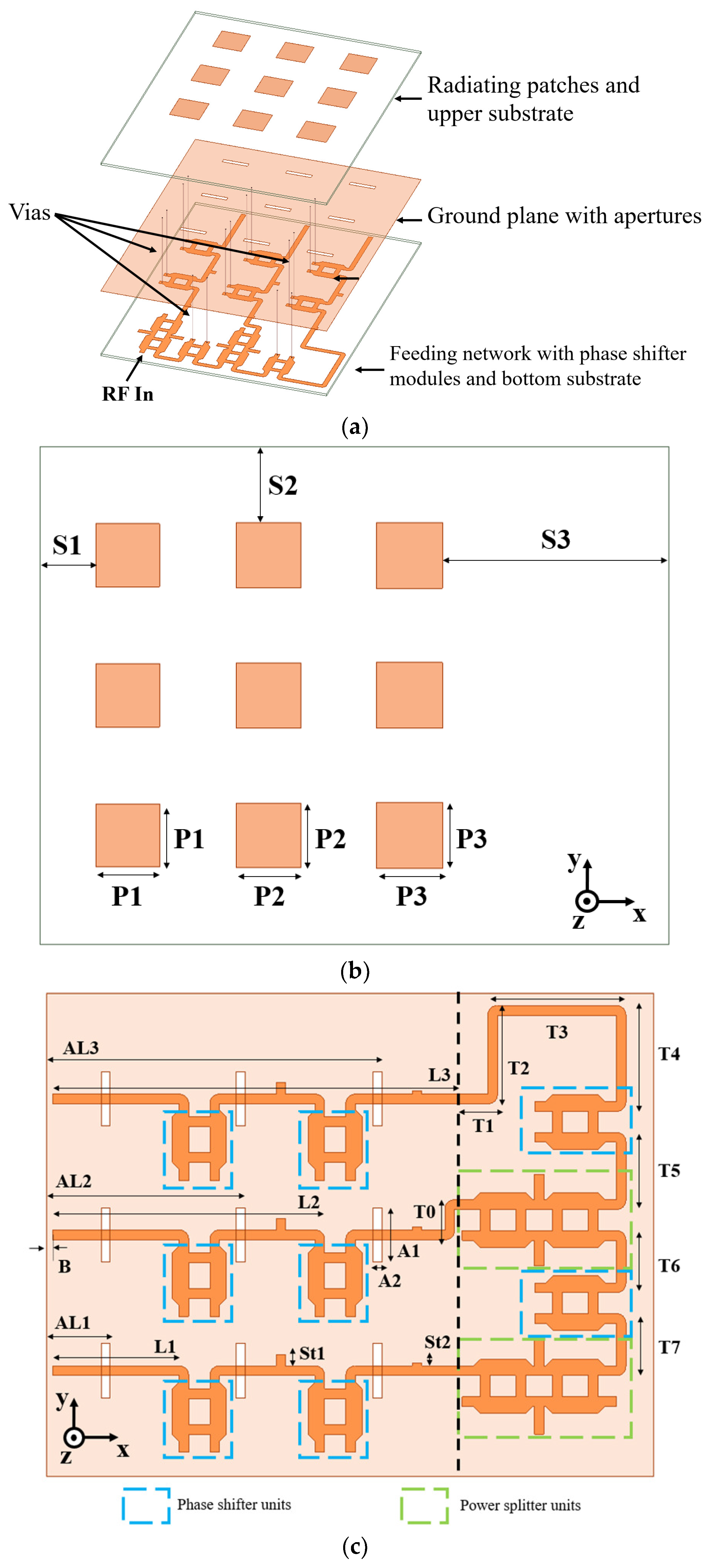
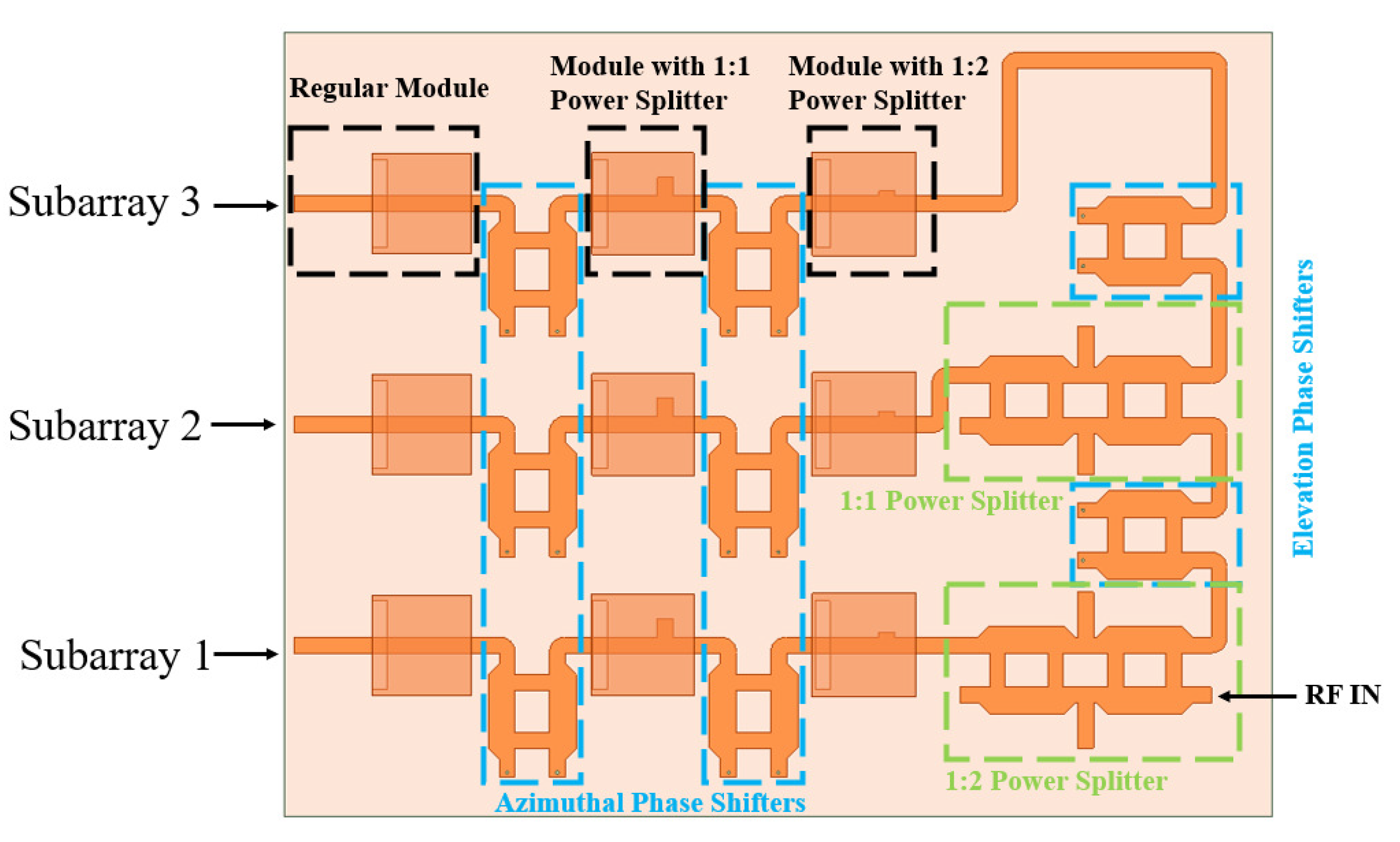
2.1. Antenna Configuration
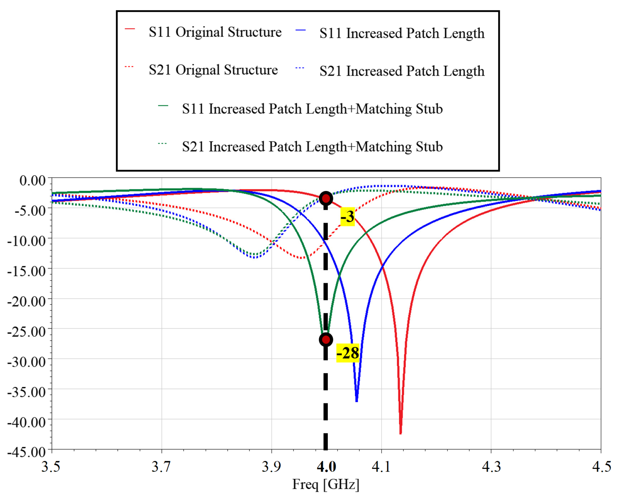
2.2. Radiating Elements
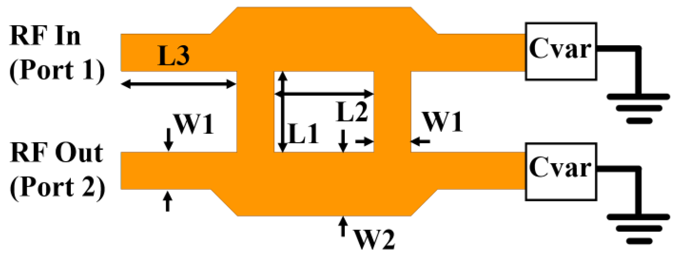
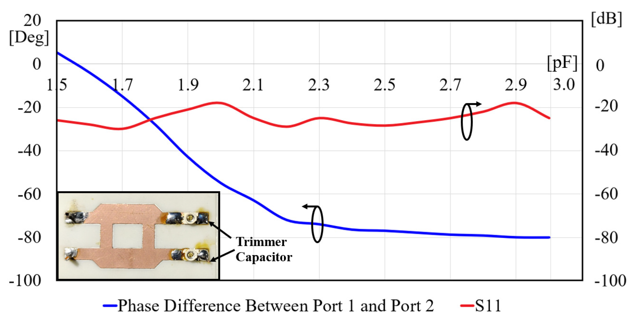
2.3. Phase Shifter
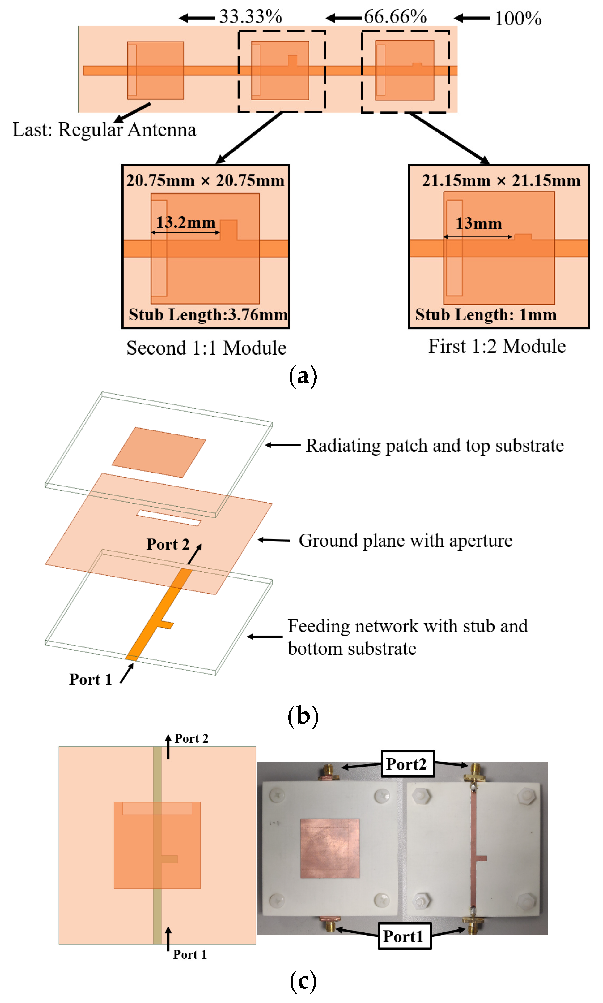
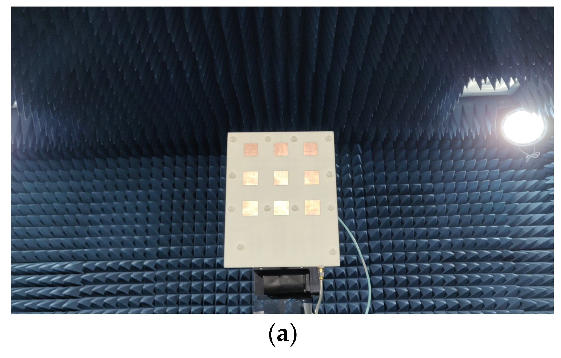
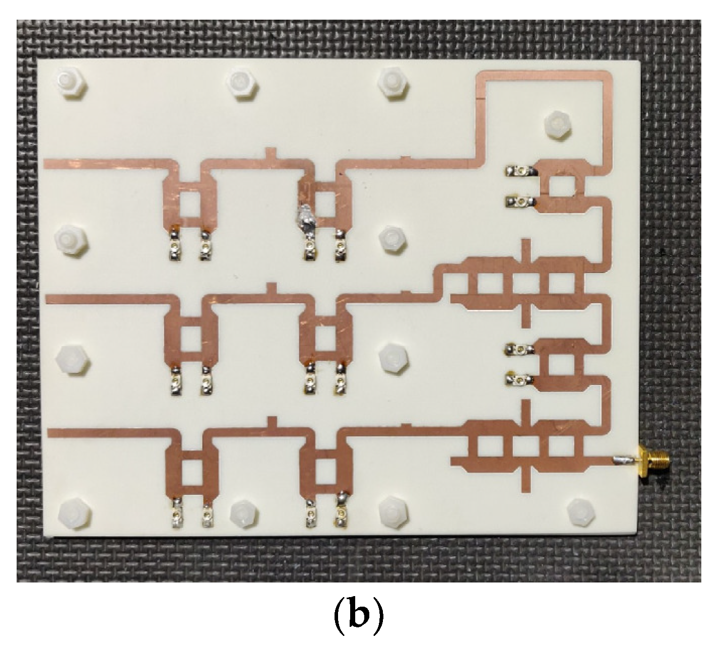
2.4. Integration
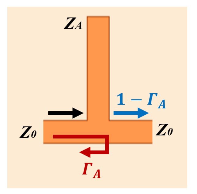
2.5. Power Splitter
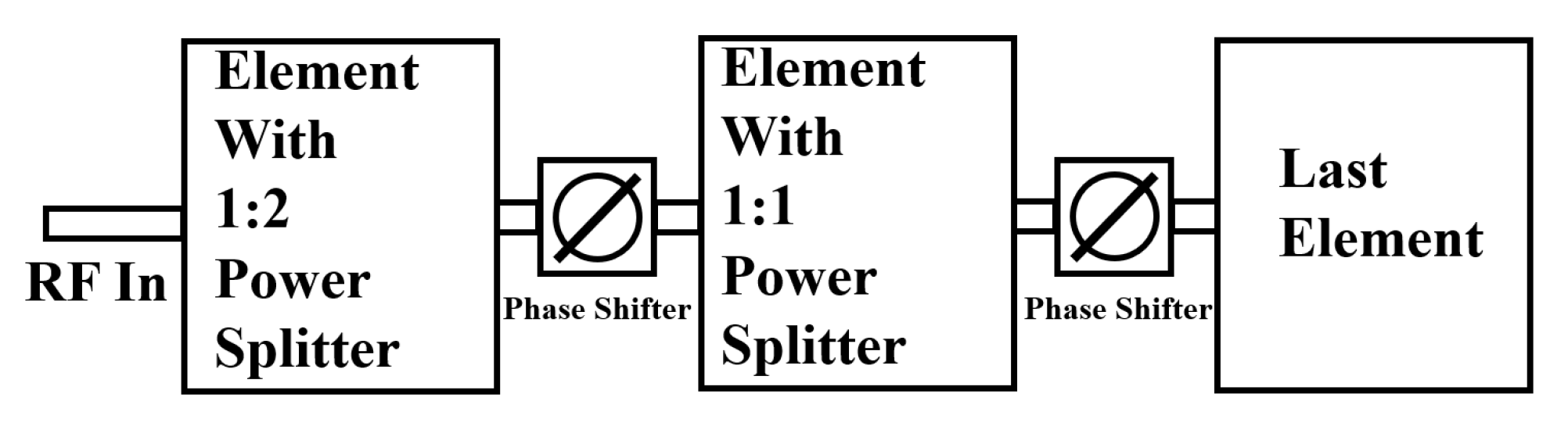
2.6. Mechanism of Phased Array
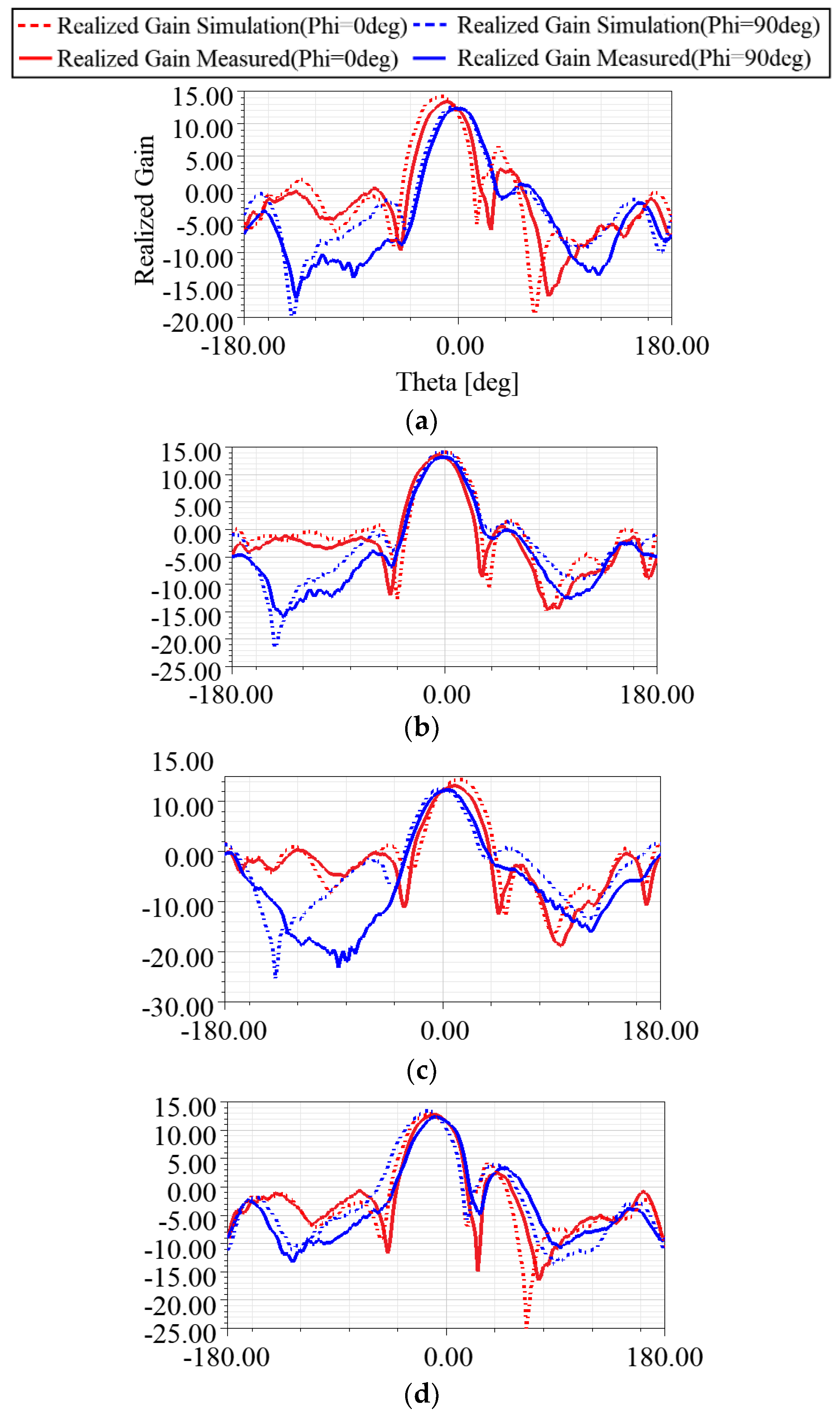
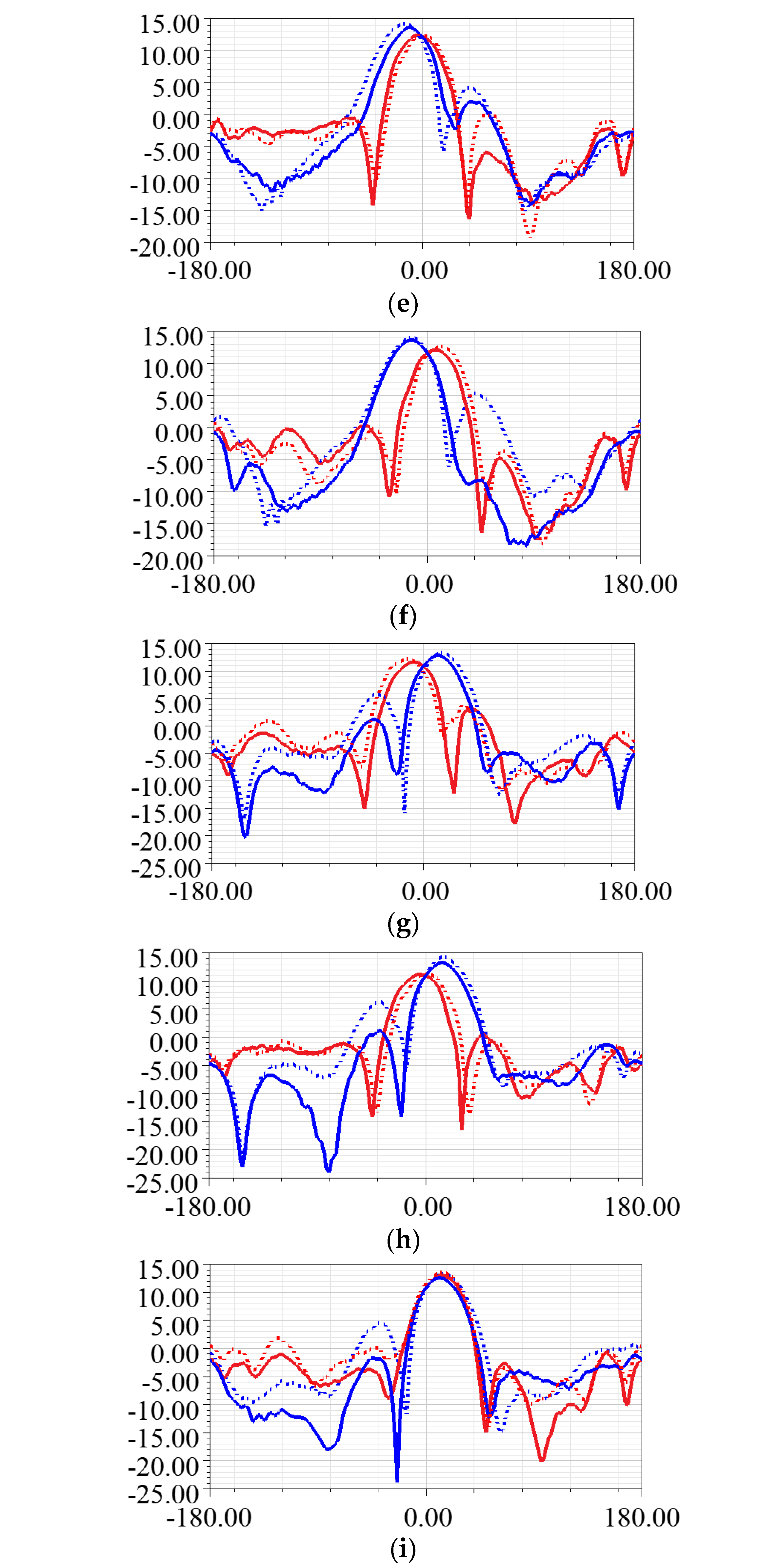
3. Numerical and Experimental Results
4. Conclusions
Author Contributions
Funding
Institutional Review Board Statement
Informed Consent Statement
Data Availability Statement
Conflicts of Interest
References
- Wang, Y.; Ding, X.; Zhang, L.-M.; Shao, W.; Wang, B.-Z. A Low-Cost Wideband Dual Circularly Polarized Aperiodic 2-D Phased Array. IEEE Trans. Antennas Propag. 2023, 71, 3080–3090. [Google Scholar] [CrossRef]
- Tombak, A.; Mortazawi, A. A novel low-cost beam-steering technique based on the extended-resonance power-dividing method. IEEE Trans. Microw. Theory Tech. 2004, 52, 664–670. [Google Scholar] [CrossRef]
- Ji, Y.; Ge, L.; Wang, J.; Chen, Q.; Wu, W.; Li, Y. Reconfigurable Phased-Array Antenna Using Continuously Tunable Substrate Integrated Waveguide Phase Shifter. IEEE Trans. Antennas Propag. 2019, 67, 6894–6908. [Google Scholar] [CrossRef]
- Lian, R.; Wang, Z.; Yin, Y.; Wu, J.; Song, X. Design of a Low-Profile Dual-Polarized Stepped Slot Antenna Array for Base Station. IEEE Antennas Wirel. Propag. Lett. 2016, 15, 362–365. [Google Scholar] [CrossRef]
- Chen, H.-D.; Sim, C.-Y.-D.; Wu, J.-Y.; Chiu, T.-W. Broadband High-Gain Microstrip Array Antennas for WiMAX Base Station. IEEE Trans. Antennas Propag. 2012, 60, 3977–3980. [Google Scholar] [CrossRef]
- Ding, C.; Guo, Y.J.; Qin, P.-Y.; Yang, Y. A Compact Microstrip Phase Shifter Employing Reconfigurable Defected Microstrip Structure (RDMS) for Phased Array Antennas. IEEE Trans. Antennas Propag. 2015, 63, 1985–1996. [Google Scholar] [CrossRef]
- Pozar, D.M. Microwave Engineering, 4th ed.; Wiley: Hoboken, NJ, USA, 2012. [Google Scholar]
- Kim, D.; Hwang, M.; Kim, G.; Kim, S. Self-Deployable Circularly Polarized Phased Yagi–Uda Antenna Array Using 3-D Printing Technology for CubeSat Applications. IEEE Antennas Wirel. Propag. Lett. 2022, 21, 2249–2253. [Google Scholar] [CrossRef]
- Pozar, D.M. A Review of Aperture Coupled Microstrip Antennas: History, Operation, Development, and Applications; University of Massachusetts at Amherst: Amherst, MA, USA, 1996; pp. 1–9. [Google Scholar]
- Yang, G. Series Aperture Coupled Fed Phased Array Antenna. Ph.D. Dissertation, Lyle School of Engineering, Southern Methodist University, Dallas, TX, USA, 2023. Chapter 5. pp. 50–65. Available online: https://scholar.smu.edu/engineering_electrical_etds/67 (accessed on 1 February 2024).
- JZ Series (Datasheet). Available online: https://www.knowlescapacitors.com/Products/Capacitors/Trimmer/Half-Turn/JZ-Series (accessed on 1 February 2024).
- Yang, G. Series Aperture Coupled Fed Phased Array Antenna. Ph.D. Dissertation, Lyle School of Engineering, Southern Methodist University, Dallas, TX, USA, 2023. Chapter 3. pp. 39–42. Available online: https://scholar.smu.edu/engineering_electrical_etds/67 (accessed on 1 February 2024).
- Guan, D.; Zhang, Y.; Qian, Z.; Li, Y.; Asaadi, M.; Ding, C. A Novel 2-D Multibeam Antenna Without Beamforming Network. IEEE Trans. Antennas Propag. 2016, 64, 3177–3180. [Google Scholar] [CrossRef]
- Wen, Y.-Q.; Gao, S.; Wang, B.-Z.; Luo, Q. Dual-Polarized and Wide-Angle Scanning Microstrip Phased Array. IEEE Trans. Antennas Propag. 2018, 66, 3775–3780. [Google Scholar] [CrossRef]
- Khalily, M.; Tafazolli, R.; Rahman, T.A.; Kamarudin, M.R. Design of Phased Arrays of Series-Fed Patch Antennas with Reduced Number of the Controllers for 28-GHz mm-Wave Applications. IEEE Antennas Wirel. Propag. Lett. 2016, 15, 1305–1308. [Google Scholar] [CrossRef]
- Kothapudi, V.K.; Kumar, V. A 6-Port Two-Dimensional 3 × 3 Series-Fed Planar Array Antenna for Dual-Polarized X-Band Airborne Synthetic Aperture Radar Applications. IEEE Access 2018, 6, 12001–12007. [Google Scholar] [CrossRef]


| Parameter | Value (mm) | Parameter | Value (mm) |
|---|---|---|---|
| P1 | 20.30 | T7 | 14.00 |
| P2 | 20.75 | A1 | 18.00 |
| P3 | 21.15 | A2 | 3.00 |
| S1 | 17.85 | L1 | 45.00 |
| S2 | 24.85 | L2 | 90.00 |
| S3 | 72.425 | L3 | 135.00 |
| T0 | 13.00 | AL1 | 21.00 |
| T1 | 13.00 | AL2 | 65.70 |
| T2 | 32.50 | AL3 | 111.00 |
| T3 | 45.00 | St1 | 3.76 |
| T4 | 32.00 | St2 | 1.00 |
| T5 | 18.00 | B | 2.00 |
| T6 | 14.00 |
| Module# (From the Input) | Return Loss (Sim./Meas.,dB) | Power Transmitted (Sim./Meas.,dB) | Power Radiated (Sim./Meas.,dB) |
|---|---|---|---|
| First | −29.95/−26.70 | −1.76/−1.78 | −4.77/−4.73 |
| Second | −29.25/−27.22 | −3.00/−2.98 | −3.01/−3.04 |
| Third (Last) | −30.48/−28.35 | NA | −0.01/−0.03 |
| Feature | [13] | [14] | [15] | [16] | This Work |
|---|---|---|---|---|---|
| Operating Frequency (GHz) | 12 | 5.2 | 28 | 9.65 | 4 |
| No. of Input Port | 9 | 36 | 4–6 | 6 | 1 |
| No. of Element | 3 × 3 | 6 × 6 | 3 × 3 | 3 × 3 | 3 × 3 |
| Boresight Gain (dBi) | 10.45 | 18.1 | 14.9 | 12.5 | 13.2 |
| * | 2 × 2 (phased array system not included) | 3 × 3 (phased array system not included) | 2 × 2 (phased array system not included) | 3.26 × 3.26 (phased array system not included) | 2.68 × 2.13 (phased array system included) |
Disclaimer/Publisher’s Note: The statements, opinions and data contained in all publications are solely those of the individual author(s) and contributor(s) and not of MDPI and/or the editor(s). MDPI and/or the editor(s) disclaim responsibility for any injury to people or property resulting from any ideas, methods, instructions or products referred to in the content. |
© 2024 by the authors. Licensee MDPI, Basel, Switzerland. This article is an open access article distributed under the terms and conditions of the Creative Commons Attribution (CC BY) license (https://creativecommons.org/licenses/by/4.0/).
Share and Cite
Yang, G.; Lee, C.S.; Zhang, L. A Novel Topology of a 3 × 3 Series Phased Array Antenna with Aperture-Coupled Feeding. Sensors 2024, 24, 6128. https://doi.org/10.3390/s24186128
Yang G, Lee CS, Zhang L. A Novel Topology of a 3 × 3 Series Phased Array Antenna with Aperture-Coupled Feeding. Sensors. 2024; 24(18):6128. https://doi.org/10.3390/s24186128
Chicago/Turabian StyleYang, Guang, Choon Sae Lee, and Linsheng Zhang. 2024. "A Novel Topology of a 3 × 3 Series Phased Array Antenna with Aperture-Coupled Feeding" Sensors 24, no. 18: 6128. https://doi.org/10.3390/s24186128