
Dual-Band Passive Beam Steering Antenna Technologies for Satellite Communication and Modern Wireless Systems: A Review
 ,
,  , , and
Abstract
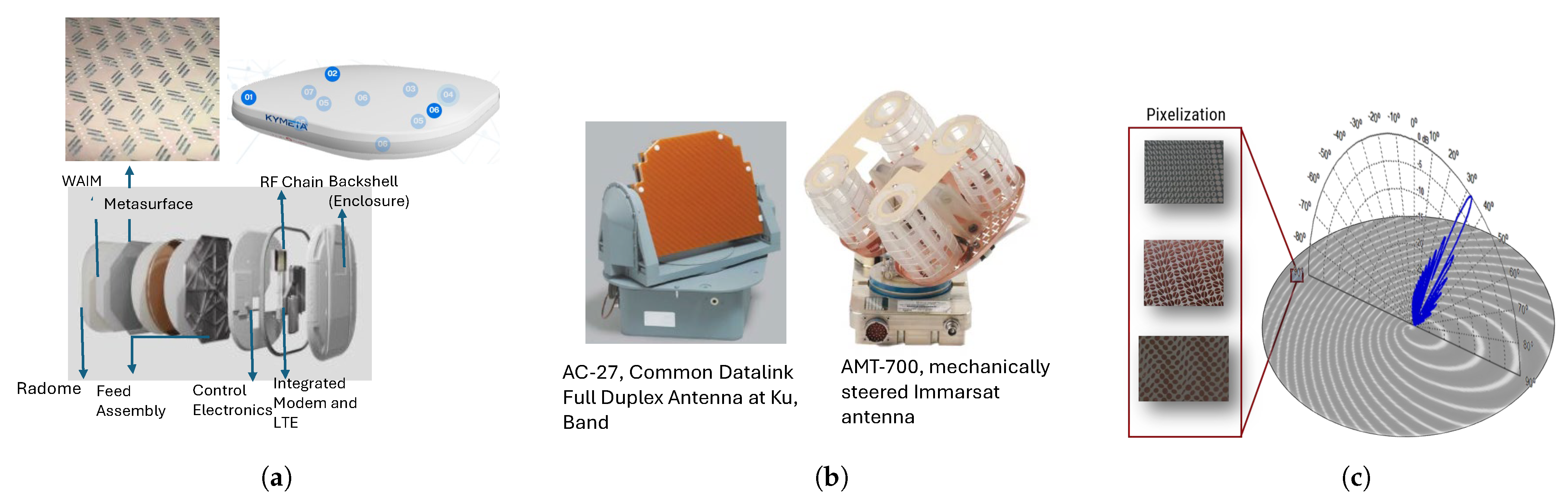
:1. Introduction
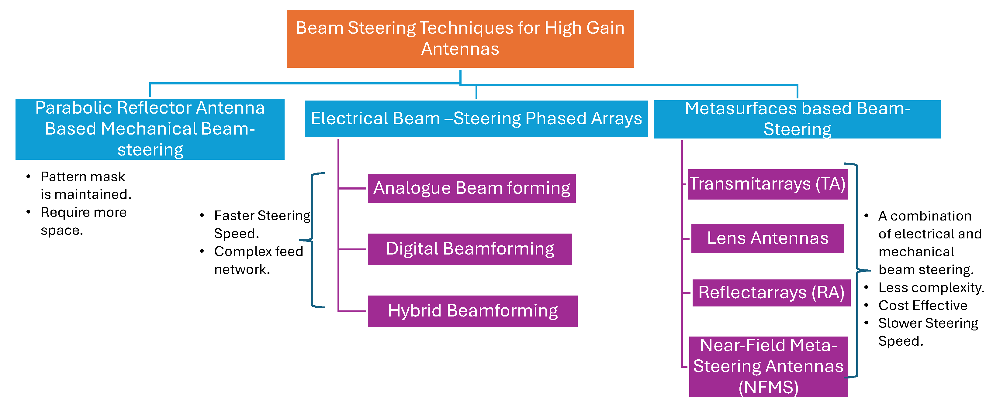
2. Beam Steering Antenna Technologies

| Technique | Reconfigurable | Steering Mechanism | Feed Network Complexity | Metasurface Type | EIRP | G/T | |
|---|---|---|---|---|---|---|---|
| Transmitarrays [32,33,34,35,36,37] | No | Mechanical Translation/rotation of feed or surface | Less | Passive | 22.3–77.5 | Medium to High | Medium to High |
| Reconfigurable Reflectarrays [38,39,40,41] | Possible | Electrical using PIN or Varactor diodes, and Motor in some cases | More | Active | 7–69.41 | Low to High | Low to High |
| Phased Arrays [29,42,43] | Possible | Electrical | More | Active | High | High | High |
| Near Field Meta-steering [31] | No | Mechanical rotation of metasurface | Least | Passive | Medium | N/A | N/A |
3. Scope and Methodology
- The review encapsulates passive beam steering techniques focusing on full-duplex systems incorporating passive metasurfaces.
- Since the first step in designing a passive metasurface is finalizing the phase shifting cell, a subwavelength element that repeats periodically/aperiodically over the entire surface, careful design and selection are crucial and require deliberation. Therefore, the focus of this article is the design analysis of different dual-band phase transformation cell topologies available in the literature, with the pros and cons of each on the system-level parameters. This analysis aims to provide a valuable resource for designers beginning the development of dual-band PGMs used in various applications such as dual-band beam steering, dual-band phase correction, and dual-band lenses.
4. Dual-Band Passive Metasurface Based Beam Steering Techniques
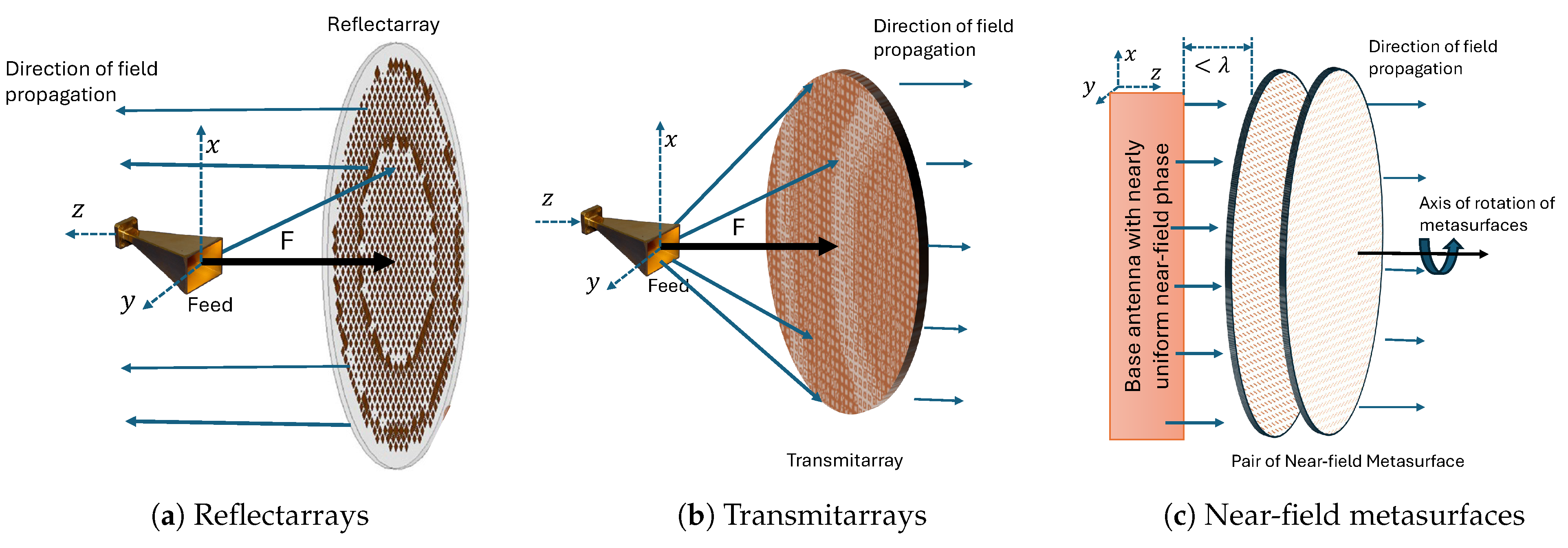
4.1. Reflectarray-Based Beam Steering
4.2. Transmitarrays-Based Beam Steering
4.3. Near-Field Meta-Steering Systems
4.4. A Comparative Analysis of Antenna Beam Steering Based on RAs, TAs and NFMS
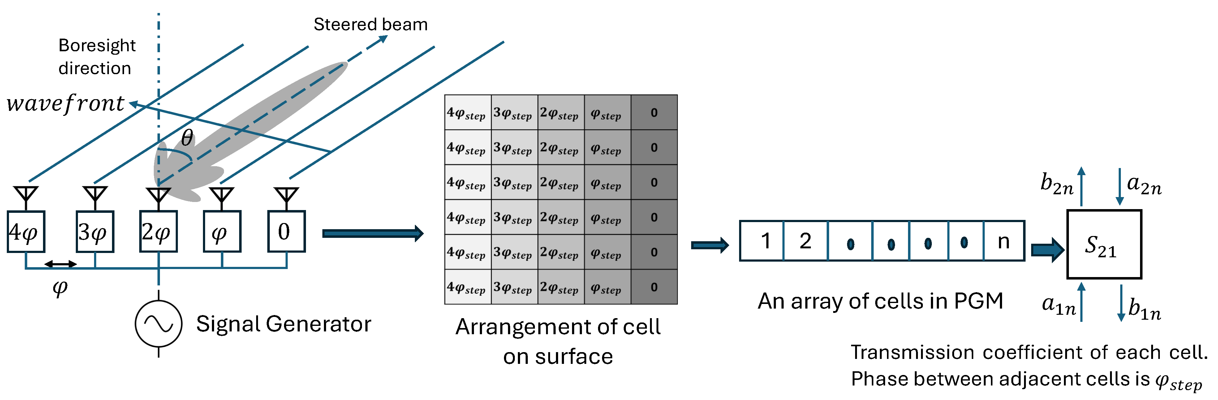
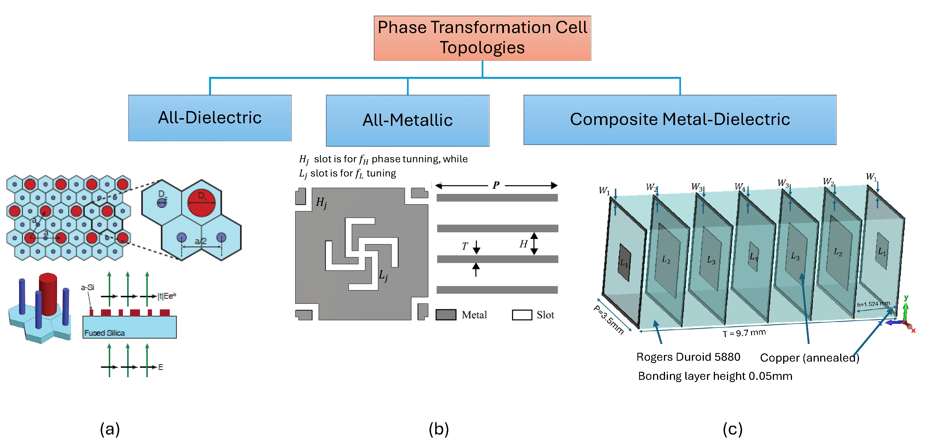
5. Passive Dual-Band Phase-Gradient Metasurfaces
5.1. All-Dielectric Unit Cells
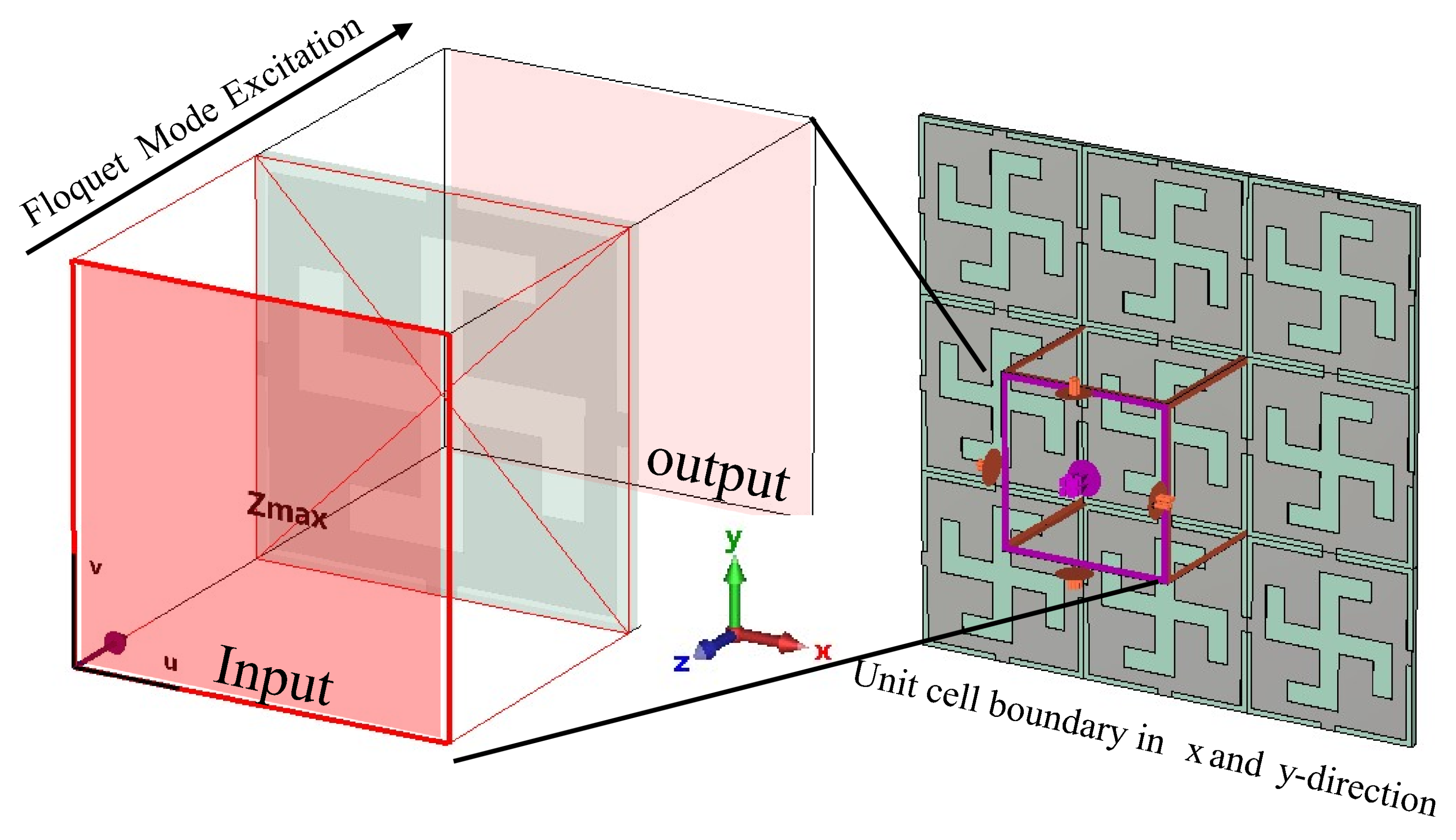
5.2. All-Metallic Unit Cells
5.3. Composite Metal-Dielectric Unit Cells
6. A Comparison of Different Dual-Band Phase-Transformation Cells
7. A Comparative Analysis of Various Reported Dual-Band Passive Metasurfaces Based Antenna Systems
8. Conclusions
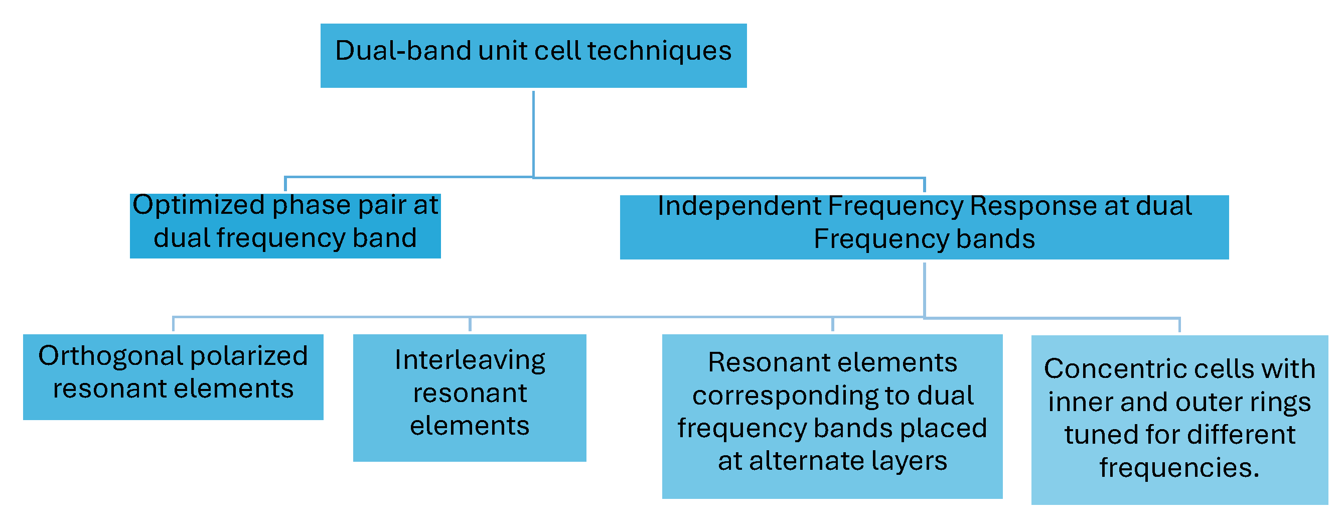
- Interleaved resonant elements [31,33,60,63,64,65,66,68,69,83,100,101]: This technique enables independent tuning but may result in larger cell sizes that may lead to phase quantization error or grating lobes particularly at a higher-frequency band. The placement of cells to form the PGM needs careful investigation to avoid corner element shape discontinuities. Smaller unit cell topologies need to be explored to design a PGM that can allow better resolution in phase correction/tunning and enhance the overall steering range of the antenna system.
- Concentric cell [67]: The designed cell has a modified Jerusalem cross resonator and a modified complementary split ring resonator to tune transmission properties at two frequencies independently. The overall cell is concentric but at the cost of complex geometry for the overall cell.
Author Contributions
Funding
Institutional Review Board Statement
Informed Consent Statement
Data Availability Statement
Conflicts of Interest
Abbreviations
| SATCOM | Satellite Communications |
| COTM | Communication on the move |
| ITU | International Telecommunication Union |
| LEO | Lower Earth Orbit |
| MEO | Medium Earth Orbit |
| GEO | Geostationary Earth Orbit |
| EIRP | Effective Isotropically Radiated Power |
| G/T | Gain-to-noise temperature |
| PGM | Phase-Gradient Metasurface |
| RF | Radio Frequency |
| SOTM | SATCOM on the Move |
| NFMS | Near-Field Meta-Steering |
| RA | Reflectarray |
| TA | Transmitarray |
| RHCP | Right Hand Circularly Polarized |
| LHCP | Left Hand Circularly Polarized |
| PSS | Phase Shifting Surfaces |
| MWS | Microwave Studio |
| PD | Phase Delay |
| PCB | Printed Circuit Board |
| PR | Phase Rotation |
References
- Skyquest. Satellite Data Services Market Insights. Available online: https://www.skyquestt.com/report/satellite-data-services-market (accessed on 31 July 2024).
- Fortune Business Insight. Fortune Business Insights: Satcom Market. Available online: https://www.fortunebusinessinsights.com/satellite-communication-satcom-market-102679 (accessed on 31 July 2024).
- Statista. Internet Usage Worldwide—Statistics & Facts. Available online: https://www.statista.com/topics/1145/internet-usage-worldwide/#topicOverview (accessed on 31 July 2024).
- Straitsresearch. Satellite Communication Market. Available online: https://straitsresearch.com/report/satellite-communicationmarket#:~:text=Market%20Overview,period%20(2022%E2%80%932030) (accessed on 31 July 2024).
- You, R.; Gao, W.; Wu, C.; Li, H. Technologies for Spacecraft Antenna Engineering Design; Springer: Singapore, 2021. [Google Scholar]
- Viasat. Satellite Communications in 2024: The Ins and Outs. Available online: https://news.viasat.com/blog/corporate/satellite-communications-in-2024-the-ins-and-outs (accessed on 31 July 2024).
- Huang, J.; Cao, J. Recent development of commercial satellite communications systems. In Artificial Intelligence in China: Proceedings of the International Conference on Artificial Intelligence in China (Lecture Notes in Electrical Engineering Book 572); Springer: Singapore, 2020; pp. 531–536. [Google Scholar]
- Imarc. Top Players in the Satellite Communication (SATCOM) Market. Available online: https://www.imarcgroup.com/satellite-communication-companies (accessed on 31 July 2024).
- RF Wireless World. Advantages and Disadvantages of LEO Orbit. Available online: https://www.rfwireless-world.com/Terminology/Advantages-and-Disadvantages-of-LEO-orbit.html (accessed on 31 July 2024).
- Lockie, D.G.; Thomson, M. Spacecraft Antennas and Beam Steering Methods for Satellite Communciation System. US Patent 5,642,122, 24 June 1997. [Google Scholar]
- Osoro, O.B.; Oughton, E.J. A techno-economic framework for satellite networks applied to low earth orbit constellations: Assessing Starlink, OneWeb and Kuiper. IEEE Access 2021, 9, 141611–141625. [Google Scholar] [CrossRef]
- He, Y.; Yang, F.; Han, G.; Li, Y. High-throughput SatCom-on-the-move antennas: Technical overview and state-of-the-art. Digit. Commun. Netw. 2023, in press.
- Uchendu, I.; Kelly, J.R. Survey of beam steering techniques available for millimeter wave applications. Prog. Electromagn. Res. 2016, 68, 35–54. [Google Scholar] [CrossRef]
- Zarb-Adami, K.; Faulkner, A.; De Vaate, J.B.; Kant, G.; Picard, P. Beamforming techniques for large-N aperture arrays. In Proceedings of the 2010 IEEE International Symposium on Phased Array Systems and Technology, Waltham, MA, USA, 12–15 October 2010; pp. 883–890. [Google Scholar]
- Rudge, A.; Withers, M. New technique for beam steering with fixed parabolic reflectors. Proc. Inst. Electr. Eng. 1971, 118, 857–863. [Google Scholar] [CrossRef]
- EM Solutions. Available online: https://www.emsolutions.com.au/products-and-solutions/sotm/ (accessed on 1 September 2024).
- Boriskin, A.; Sauleau, R. Aperture Antennas for Millimeter and Sub-Millimeter Wave Applications; Springer: Cham, Switzerland, 2018. [Google Scholar]
- Sazegar, M.; Nassar, I.; Eylander, C.; Momeni, A.; Eylander, B.; Stevenson, R. Ku-Band SATCOM User Terminal with Complete Beam Steering Using a Shared Aperture Metasurface for Full-Duplex Operation. In Proceedings of the 2023 17th European Conference on Antennas and Propagation (EuCAP), Florence, Italy, 26–31 March 2023; pp. 1–3. [Google Scholar]
- Kymeta Corporation. Kymeta Terminal. Available online: https://www.kymetacorp.com/products/terminal/ (accessed on 1 September 2024).
- ThinKom Solutions. ThinKom. Available online: https://www.thinkom.com/technology (accessed on 1 September 2024).
- Kymeta Corporation. Starlink for Homes. Available online: https://www.starlink.com/residential?utm_source=google&utm_medium=paid&utm_campaign=lf_au_res_egn_src_ggl_brd_stk-pe&utm_content=694470362766&utm_term=starlink&utm_id=&gad_source=1&gclid=EAIaIQobChMI18yNvuW5hQMVlhitBh2UggomEAAYASAAEgLbEPD_BwE (accessed on 1 September 2024).
- Gagnon, N. Phase Shifting Surface (PSS) and Phase and Amplitude Shifting Surface (PASS) for Microwave Applications; University of Ottawa: Ottawa, ON, Canada, 2011. [Google Scholar]
- Afzal, M.U.; Esselle, K.P. Steering the beam of medium-to-high gain antennas using near-field phase transformation. IEEE Trans. Antennas Propag. 2017, 65, 1680–1690. [Google Scholar] [CrossRef]
- Akbari, M.; Farahani, M.; Ghayekhloo, A.; Zarbakhsh, S.; Sebak, A.R.; Denidni, T.A. Beam tilting approaches based on phase gradient surface for mmWave antennas. IEEE Trans. Antennas Propag. 2020, 68, 4372–4385. [Google Scholar] [CrossRef]
- Singh, K.; Ahmed, F.; Esselle, K. Electromagnetic metasurfaces: Insight into evolution, design and applications. Crystals 2022, 12, 1769. [Google Scholar] [CrossRef]
- Singh, K.; Afzal, M.U.; Kovaleva, M.; Esselle, K.P. Controlling the most significant grating lobes in two-dimensional beam-steering systems with phase-gradient metasurfaces. IEEE Trans. Antennas Propag. 2019, 68, 1389–1401. [Google Scholar] [CrossRef]
- Singh, K.; Afzal, M.U.; Esselle, K.P. Designing efficient phase-gradient metasurfaces for near-field meta-steering systems. IEEE Access 2021, 9, 109080–109093. [Google Scholar] [CrossRef]
- Zhao, X.; Yuan, C.; Liu, L.; Peng, S.; Zhang, Q.; Zhou, H. All-metal transmit-array for circular polarization design using rotated cross-slot elements for high-power microwave applications. IEEE Trans. Antennas Propag. 2017, 65, 3253–3256. [Google Scholar] [CrossRef]
- Gültepe, G.; Kanar, T.; Zihir, S.; Rebeiz, G.M. A 1024-element Ku-band SATCOM dual-polarized receiver with > 10-dB/KG/T and embedded transmit rejection filter. IEEE Trans. Microw. Theory Tech. 2021, 69, 3484–3495. [Google Scholar] [CrossRef]
- Buchanan, N.; Fusco, V.; Pal, A. Squinted elevation antenna for Ku band DVB satellite reception with electronically steered azimuth. In Proceedings of the 2017 11th European Conference on Antennas and Propagation (EUCAP), Paris, France, 19–24 March 2017; pp. 3437–3440. [Google Scholar]
- Ahmed, F.; Afzal, M.U.; Esselle, K.P.; Thalakotuna, D.N. Novel Dual-Band Phase-Gradient Metascreen and Dual-Band Near-Field Meta-Steering Antenna. IEEE Trans. Antennas Propag. 2024, 72, 2202–2216. [Google Scholar] [CrossRef]
- Matos, S.A.; Lima, E.B.; Silva, J.S.; Costa, J.R.; Fernandes, C.A.; Fonseca, N.J.; Mosig, J.R. High gain dual-band beam-steering transmit array for satcom terminals at Ka-band. IEEE Trans. Antennas Propag. 2017, 65, 3528–3539. [Google Scholar] [CrossRef]
- Pham, T.K.; Guang, L.; González-Ovejero, D.; Sauleau, R. Dual-band transmitarray with low scan loss for satcom applications. IEEE Trans. Antennas Propag. 2020, 69, 1775–1780. [Google Scholar] [CrossRef]
- Song, L.Z.; Zhang, T.; Lai, J.X.; Yang, Y.; Du, J. A 180 GHz to 220 GHz wideband transmitarray with wide-angle beam steering for intersatellite communications. IEEE Trans. Antennas Propag. 2023, 72, 950–955. [Google Scholar] [CrossRef]
- Madi, R.; Clemente, A.; Sauleau, R. Dual-Band, Aperture-Shared Transmitarray for Vehicular SatCom Applications. IEEE Access 2023, 11, 71088–71096. [Google Scholar] [CrossRef]
- Yang, G.; Zhang, S. Dual-band shared-aperture multiple antenna system with beam steering for 5G applications. IEEE Trans. Circuits Syst. II Express Briefs 2022, 69, 4804–4808. [Google Scholar] [CrossRef]
- Yang, S.; Yan, Z.; Cai, M.; Li, X. Low-profile dual-band circularly polarized antenna combining transmitarray and reflectarray for satellite communications. IEEE Trans. Antennas Propag. 2022, 70, 5983–5988. [Google Scholar] [CrossRef]
- Teng, M.; Yu, S.; Kou, N. A Dual-Band Beam-Steering Array Antenna with Integration of Reflectarray and Phased Array. IEEE Antennas Wirel. Propag. Lett. 2023, 22, 1241–1245. [Google Scholar] [CrossRef]
- Sangmahamd, P.; Janpugdee, P.; Zhao, Y. A Metasurface-Based Electronically Reconfigurable and Dual-Polarized Reflectarray Antenna for Beam-Steering Applications. IEEE Access 2023, 11, 137414–137425. [Google Scholar] [CrossRef]
- Li, K.; Zhou, T.; Cai, Y.; Liu, S.; Wang, F.; Ren, Y. A Reconfigurable Beam-Scanning Reflectarray with Switchable Polarization Using Independently Controlled Dual-Linearly Polarized Units. IEEE Antennas Wirel. Propag. Lett. 2024, 23, 1508–1512. [Google Scholar] [CrossRef]
- Sreekavya, M.; Ghosh, B.; Majumder, B. Dual-Band, Dual-Polarized Reconfigurable Reflectarray Antenna Operating at C and X Band. In Proceedings of the 2024 IEEE Wireless Antenna and Microwave Symposium (WAMS), Visakhapatnam, India, 29 February–3 March 2024; pp. 1–5. [Google Scholar]
- Liu, S.; Jiang, K.; Xu, G.; Ding, X.; Zhang, K.; Fu, J.; Wu, Q. A dual-band shared aperture antenna array in Ku/Ka-bands for beam scanning applications. IEEE Access 2019, 7, 78794–78802. [Google Scholar] [CrossRef]
- Kymeta. Kymeta Corp. Available online: https://www.kymetacorp.com/resources/#technical-paper (accessed on 1 September 2024).
- Chaloun, T.; Boccia, L.; Arnieri, E.; Fischer, M.; Valenta, V.; Fonseca, N.J.; Waldschmidt, C. Electronically steerable antennas for future heterogeneous communication networks: Review and perspectives. IEEE J. Microwaves 2022, 2, 545–581. [Google Scholar] [CrossRef]
- Honeywell. Honeywell Aerospace Technologies. Available online: https://aerospace.honeywell.com/us/en/products-and-services/product/hardware-and-systems/satellite-communications/amt-700-antenna (accessed on 28 August 2024).
- Waveup. Wave Up Innovation in Electromagnetics. Available online: http://www.wave-up.it/technologies/ (accessed on 28 August 2024).
- Esselle, K.; Singh, K.; Thalakotuna, D.; Koli, M.N.Y.; Ahmed, F. Beam-steering antenna technologies for space-related applications. In Proceedings of the 2023 17th European Conference on Antennas and Propagation (EuCAP), Florence, Italy, 26–31 March 2023; pp. 1–5. [Google Scholar]
- Esselle, K.P. A brief overview of antenna technologies for communications-on-the-move satellite communication mobile terminals. In Proceedings of the 2020 IEEE International Symposium on Antennas and Propagation and North American Radio Science Meeting, Montreal, QC, Canada, 5–10 July 2020; pp. 1637–1638. [Google Scholar]
- Fonseca, N.J.; Toso, G.; van der Vorst, M.; Jankovic, P.; Angeletti, P. A review of lens-based antenna developments supported by esa for future satellite missions. In Proceedings of the 2018 International Symposium on Antennas and Propagation (ISAP), Busan, Republic of Korea, 23–26 October 2018; pp. 1–2. [Google Scholar]
- Ahmed, F.; Singh, K.; Esselle, K.P. State-of-the-art passive beam-steering antenna technologies: Challenges and capabilities. IEEE Access 2023, 11, 69101–69116. [Google Scholar] [CrossRef]
- Berry, D.; Malech, R.; Kennedy, W. The reflectarray antenna. IEEE Trans. Antennas Propag. 1963, 11, 645–651. [Google Scholar] [CrossRef]
- Mirmozafari, M.; Zhang, Z.; Gao, M.; Zhao, J.; Honari, M.M.; Booske, J.H.; Behdad, N. Mechanically reconfigurable, beam-scanning reflectarray and transmitarray antennas: A review. Appl. Sci. 2021, 11, 6890. [Google Scholar] [CrossRef]
- Budhu, J.; Grbic, A.; Michielssen, E. Dualband stacked metasurface reflectarray. In Proceedings of the 2020 IEEE International Symposium on Antennas and Propagation and North American Radio Science Meeting, Montreal, QC, Canada, 5–10 July 2020; pp. 821–822. [Google Scholar]
- Baladi, E.; Xu, M.Y.; Faria, N.; Nicholls, J.; Hum, S.V. Dual-band circularly polarized fully reconfigurable reflectarray antenna for satellite applications in the Ku-band. IEEE Trans. Antennas Propag. 2021, 69, 8387–8396. [Google Scholar] [CrossRef]
- Nam, Y.H.; Kim, Y.; Lee, S.G.; Lee, J.H. Hybrid reflectarray antenna of passive and active unit cells for highly directive two-direction beam steering. IEEE Access 2022, 11, 6299–6304. [Google Scholar] [CrossRef]
- Luo, Q.; Gao, S.; Li, W.; Sobhy, M.; Bakaimi, I.; de Groot, C.K.; Hayden, B.; Reaney, I.; Yang, X. Multibeam dual-circularly polarized reflectarray for connected and autonomous vehicles. IEEE Trans. Veh. Technol. 2019, 68, 3574–3585. [Google Scholar] [CrossRef]
- Chi, P.L.; Cheng, Y.H.; Yang, T. Novel Dual-Frequency Independent Beam-Scanning Reflectarray. In Proceedings of the 2023 IEEE International Symposium on Antennas and Propagation and USNC-URSI Radio Science Meeting (USNC-URSI), Portland, OR, USA, 23–28 July 2023; pp. 1337–1338. [Google Scholar]
- Dussopt, L. Transmitarray antennas. In Aperture Antennas for Millimeter and Sub-Millimeter Wave Applications; Springer: Berlin/Heidelberg, Germany, 2018; pp. 191–220. [Google Scholar]
- Zeng, Q.; Xue, Z.; Ren, W.; Li, W. Dual-band beam-scanning antenna using rotatable planar phase gradient transmitarrays. IEEE Trans. Antennas Propag. 2020, 68, 5021–5026. [Google Scholar] [CrossRef]
- Lei, H.; Liu, Y.; Jia, Y.; Yue, Z.; Wang, X. A low-profile dual-band dual-circularly polarized folded transmitarray antenna with independent beam control. IEEE Trans. Antennas Propag. 2021, 70, 3852–3857. [Google Scholar] [CrossRef]
- Naseri, P.; Mirzavand, R.; Mousavi, P. Dual-band circularly polarized transmit-array unit-cell at X and K bands. In Proceedings of the 2016 10th European Conference on Antennas and Propagation (EuCAP), Davos, Switzerland, 10–15 April 2016; pp. 1–4. [Google Scholar]
- Naseri, P.; Matos, S.A.; Costa, J.R.; Fernandes, C.A.; Fonseca, N.J. Dual-band dual-linear-to-circular polarization converter in transmission mode application to K/Ka-band satellite communications. IEEE Trans. Antennas Propag. 2018, 66, 7128–7137. [Google Scholar] [CrossRef]
- Wang, P.; Ren, W.; Zeng, Q.; Xue, Z.; Li, W. Dual-band beam-scanning antenna at ka-band by rotation of two transmitarrays. IEEE Antennas Wirel. Propag. Lett. 2022, 21, 1792–1796. [Google Scholar] [CrossRef]
- Aziz, A.; Zhang, X.; Yang, F.; Xu, S.; Li, M. A dual-band orthogonally polarized contour beam transmitarray design. IEEE Trans. Antennas Propag. 2021, 69, 4538–4545. [Google Scholar] [CrossRef]
- Bagheri, M.O.; Hassani, H.R.; Rahmati, B. Dual-band, dual-polarised metallic slot transmitarray antenna. IET Microwaves Antennas Propag. 2017, 11, 402–409. [Google Scholar] [CrossRef]
- Pham, K.T.; Sauleau, R.; Fourn, E.; Diaby, F.; Clemente, A.; Dussopt, L. Dual-band transmitarrays with dual-linear polarization at Ka-band. IEEE Trans. Antennas Propag. 2017, 65, 7009–7018. [Google Scholar] [CrossRef]
- Wang, S.; Chen, Y.; Gao, J.; Zhai, G.; Ding, J. Ultrathin Dual-Band Wide-Angle Beam Scanning Metalens Based on High-Efficiency Meta-Atom. Adv. Photonics Res. 2022, 3, 2100186. [Google Scholar] [CrossRef]
- Hasani, H.; Silva, J.S.; Capdevila, S.; García-Vigueras, M.; Mosig, J.R. Dual-band circularly polarized transmitarray antenna for satellite communications at (20, 30) GHz. IEEE Trans. Antennas Propag. 2019, 67, 5325–5333. [Google Scholar] [CrossRef]
- Hasani, H.; Silva, J.S.; Mosig, J.R.; Garcia-Vigueras, M. Dual-band 20/30 GHz circularly polarized transmitarray for SOTM applications. In Proceedings of the 2016 10th European Conference on Antennas and Propagation (EuCAP), Davos, Switzerland, 10–15 April 2016; pp. 1–3. [Google Scholar]
- Singh, K.; Afzal, M.U.; Esselle, K.P. Efficient Near-Field Meta-Steering Systems for Connectivity-On-The-Move Applications using Hybrid Metasurfaces. In Proceedings of the 2022 IEEE International Symposium on Antennas and Propagation and USNC-URSI Radio Science Meeting (AP-S/URSI), Denver, CO, USA, 10–15 July 2022; pp. 641–642. [Google Scholar]
- Koli, M.N.Y.; Afzal, M.U.; Esselle, K.P. Increasing the gain of beam-tilted circularly polarized radial line slot array antennas. IEEE Trans. Antennas Propag. 2022, 70, 4392–4403. [Google Scholar] [CrossRef]
- Ahmed, F.; Afzal, M.U.; Hayat, T.; Esselle, K.P.; Thalakotuna, D.N. A near-field meta-steering antenna system with fully metallic metasurfaces. IEEE Trans. Antennas Propag. 2022, 70, 10062–10075. [Google Scholar] [CrossRef]
- Baba, A.A.; Hashmi, R.M.; Attygalle, M.; Esselle, K.P.; Borg, D. Ultrawideband beam steering at mm-wave frequency with planar dielectric phase transformers. IEEE Trans. Antennas Propag. 2021, 70, 1719–1728. [Google Scholar] [CrossRef]
- Ettorre, M.; Pavone, S.; Casaletti, M.; Albani, M.; Mazzinghi, A.; Freni, A. Near-Field Focusing by Non-diffracting Bessel Beams. In Aperture Antennas for Millimeter and Sub-Millimeter Wave Applications; Springer: Cham, Switzerland, 2018; pp. 243–288. [Google Scholar]
- Huang, J. Analysis of a microstrip reflectarray antenna for microspacecraft applications. Telecommun. Data Acquis. Rep. 1995. [Google Scholar]
- Gagnon, N.; Petosa, A.; McNamara, D.A. Printed hybrid lens antenna. IEEE Trans. Antennas Propag. 2012, 60, 2514–2518. [Google Scholar] [CrossRef]
- Gagnon, N.; Petosa, A. Using rotatable planar phase shifting surfaces to steer a high-gain beam. IEEE Trans. Antennas Propag. 2013, 61, 3086–3092. [Google Scholar] [CrossRef]
- Gagnon, N.; Petosa, A.; McNamara, D.A. Thin microwave quasi-transparent phase-shifting surface (PSS). IEEE Trans. Antennas Propag. 2010, 58, 1193–1201. [Google Scholar] [CrossRef]
- Ding, F.; Pors, A.; Bozhevolnyi, S.I. Gradient metasurfaces: A review of fundamentals and applications. Rep. Prog. Phys. 2017, 81, 026401. [Google Scholar] [CrossRef]
- Bose, J.C. On the rotation of plane of polarisation of electric wave by a twisted structure. Proc. R. Soc. Lond. 1898, 63, 146–152. [Google Scholar]
- Ali, A.; Mitra, A.; Aïssa, B. Metamaterials and metasurfaces: A review from the perspectives of materials, mechanisms and advanced metadevices. Nanomaterials 2022, 12, 1027. [Google Scholar] [CrossRef]
- Balanis, C.A. Antenna Theory: Analysis and Design; John Wiley & Sons: Hoboken, NJ, USA, 2016. [Google Scholar]
- Arbabi, E.; Arbabi, A.; Kamali, S.M.; Horie, Y.; Faraon, A. Multiwavelength polarization-insensitive lenses based on dielectric metasurfaces with meta-molecules. Optica 2016, 3, 628–633. [Google Scholar] [CrossRef]
- Matos, S.A.; Lima, E.B.; Costa, J.R.; Fernandes, C.A.; Fonseca, N.J. Generic formulation for transmit-array dual-band unit-cell design. In Proceedings of the 2017 11th European Conference on Antennas and Propagation (EUCAP), Paris, France, 19–24 March 2017; pp. 2791–2794. [Google Scholar]
- Baba, A.A.; Hashmi, R.M.; Esselle, K.P.; Weily, A.R. Compact high-gain antenna with simple all-dielectric partially reflecting surface. IEEE Trans. Antennas Propag. 2018, 66, 4343–4348. [Google Scholar] [CrossRef]
- Afzal, M.U.; Esselle, K.P.; Lalbakhsh, A. A methodology to design a low-profile composite-dielectric phase-correcting structure. IEEE Antennas Wirel. Propag. Lett. 2018, 17, 1223–1227. [Google Scholar] [CrossRef]
- Afzal, M.U.; Esselle, K.P.; Zeb, B.A. Dielectric phase-correcting structures for electromagnetic band gap resonator antennas. IEEE Trans. Antennas Propag. 2015, 63, 3390–3399. [Google Scholar] [CrossRef]
- Jain, S.; Abdel-Mageed, M.; Mittra, R. Flat-lens design using field transformation and its comparison with those based on transformation optics and ray optics. IEEE Antennas Wirel. Propag. Lett. 2013, 12, 777–780. [Google Scholar] [CrossRef]
- Emara, M.K.; Tomura, T.; Hirokawa, J.; Gupta, S. Fabry–Pérot-Based Compound All-Dielectric Huygens’ Structure for Circularly Polarized Millimeter-Wave Beamforming. IEEE Antennas Wirel. Propag. Lett. 2020, 19, 1784–1788. [Google Scholar] [CrossRef]
- Al-Nuaimi, M.K.T.; Hong, W.; Zhang, Y. Design of high-directivity compact-size conical horn lens antenna. IEEE Antennas Wirel. Propag. Lett. 2014, 13, 467–470. [Google Scholar] [CrossRef]
- Eskandari, H.; Albadalejo-Lijarcio, J.L.; Zetterstrom, O.; Tyc, T.; Quevedo-Teruel, O. H-plane horn antenna with enhanced directivity using conformal transformation optics. Sci. Rep. 2021, 11, 14322. [Google Scholar] [CrossRef]
- Holzman. A highly compact 60-GHz lens-corrected conical horn antenna. IEEE Antennas Wirel. Propag. Lett. 2004, 3, 280–282. [Google Scholar] [CrossRef]
- Munk, B.A. Frequency Selective Surfaces: Theory and Design; John Wiley & Sons: Hoboken, NJ, USA, 2005. [Google Scholar]
- Abdelrahman, A.H.; Yang, F.; Elsherbeni, A.Z.; Nayeri, P.; Balanis, C.A. Analysis and Design of Transmitarray Antennas; Springer: Berlin/Heidelberg, Germany, 2017. [Google Scholar]
- Ryan, C.G.; Chaharmir, M.R.; Shaker, J.; Bray, J.R.; Antar, Y.M.; Ittipiboon, A. A wideband transmitarray using dual-resonant double square rings. IEEE Trans. Antennas Propag. 2010, 58, 1486–1493. [Google Scholar] [CrossRef]
- Ebrahimi, A.; Withayachumnankul, W.; Al-Sarawi, S.; Abbott, D. Design of dual-band frequency selective surface with miniaturized elements. In Proceedings of the 2014 International Workshop on Antenna Technology: Small Antennas, Novel EM Structures and Materials, and Applications (iWAT), Sydney, Australia, 4–6 March 2014; pp. 201–204. [Google Scholar]
- Li, M.; Behdad, N. Wideband true-time-delay microwave lenses based on metallo-dielectric and all-dielectric lowpass frequency selective surfaces. IEEE Trans. Antennas Propag. 2013, 61, 4109–4119. [Google Scholar] [CrossRef]
- Lima, E.B.; Matos, S.A.; Costa, J.R.; Fernandes, C.A.; Fonseca, N.J. Circular polarization wide-angle beam steering at Ka-band by in-plane translation of a plate lens antenna. IEEE Trans. Antennas Propag. 2015, 63, 5443–5455. [Google Scholar] [CrossRef]
- Naseri, P.; Matos, S.A.; Costa, J.R.; Fernandes, C.A. Phase-Delay Versus Phase-Rotation Cells for Circular Polarization Transmit Arrays—Application to Satellite Ka-Band Beam Steering. IEEE Trans. Antennas Propag. 2018, 66, 1236–1247. [Google Scholar] [CrossRef]
- Nabeel, M.I.; Afzal, M.U.; Singh, K.; Thalakotuna, D.N.; Esselle, K.P. Dual-Band Printed Near-Field Metasurface with Independent Phase Transformation for Enhanced Antenna Gain. IEEE Antennas Wirel. Propag. Lett. 2024, 23, 2401–2405. [Google Scholar] [CrossRef]
- Mutluer, E.; Döken, B.; Kartal, M. A dual-band frequency selective surface design for satellite applications. In Proceedings of the 2018 18th Mediterranean Microwave Symposium (MMS), Istanbul, Turkey, 31 October–2 November 2018; pp. 43–46. [Google Scholar]
- Chaharmir, M.R.; Shaker, J. Design of a multilayer X-/Ka-band frequency-selective surface-backed reflectarray for satellite applications. IEEE Trans. Antennas Propag. 2015, 63, 1255–1262. [Google Scholar] [CrossRef]
- Shi, Y.; Zeng, Q.; Xue, Z.; Ren, W.; Li, W. Dual-band double circularly polarized wide-angle beam-scanning antenna using planar phase gradient transmitarrays. Int. J. Microw. Comput. Aided Eng. 2022, 32, e23170. [Google Scholar] [CrossRef]


| Cell Topology | Dual-Band Design | Op. Freq. BW | Fabrication, Cost | High Temp. App. |
|---|---|---|---|---|
| All-Dielectric | Complex | High | Cheaper if using PLA or ABS | Lose structural integrity |
| All-Metallic | Easy | Low | Laser cutting, suited for flat panels only | Suitable |
| Comp. Metal-Dielectric | Easy | Medium | Traditional printing technique, require expensive laminates | Suffer dielectric breakdown |
| Ref. | Resonant Element | Topology | Number of Layers | Cell Size | Frequency Capability | Polarization | Phase Control |
|---|---|---|---|---|---|---|---|
| [95] | Double Square Loop | Composite separated by air gap | 4 | Wideband (29–32 GHz) | CP | NA | |
| [101] | 4-arm structure for one band, 4-leg structure for other-band | Composite | One metal and one dielectric layer | Dual-band Ku/Ka (14.1–16 GHz and 29.2–36.8 GHz) | Dual | Separate tuning of elements by length variation | |
| [102] | Cross dipole for higher frequency, backed by square loops for lower frequency | Composite interleaved structure | Five dielectric and seven metal layers | and | Dual-band (20, 30 GHz) | CP | NA |
| [69] | Split ring center elements for lower frequency, quarter split circle at corners for higher frequency | Composite | Five metal and four dielectric layers | 0.53 and 0.8 | Dual-band (20, 30 GHz) | CP | Independent phase tuning by rotation of split rings |
| [84] | Square Patch Middle and square loop mentions shape against design frequ | Composite | seven metal and six dielectric layers | Dual-band (20, 30 GHz) | CP | Optimal Phase Pair Selection | |
| [60] | High frequency and low frequency patches | Composite | Three metal & two dielectric layers, bonded together | 0.49 and 0.6 | Dual-band (12, 15 GHz) | Dual CP | NA |
| [68] | Swastika cross slot for lower frequency, half cross slot on cell corners for higher frequency | Composite, Thin substrate separated by air gap | Three metal and three dielectric layers | Dual-band (20, 30 GHz) | CP | Independent Frequency tuning by length variation | |
| [59] | Three concentric square loops | Composite structure, bonded layers | Five metal & four dielectric layers | Dual-band (8, 14 GHz) | CP | Optimum Phase pair by length variation | |
| [33] | Vertical and Horizontal Dipoles | Composite Bonded Layers | Three metal and three dielectric layers | Dual-band (20, 30 GHz) | LP | Independent frequency tuning as the resonating elements are cross-polarized | |
| [65] | Cross slot and magnetic dipole slot | All metal | Three metal layers | Dual-band (11, 12.5 GHz) | CP | Independent frequency tuning as the resonating elements are cross-polarized | |
| [31] | Modified swastika slot in the middle for LF, and half swastika slot in corners for HF | All metal, separated by air gap | Four metal layers | Dual-band (Ku) | CP | Optimum phase pair with partially independent phase response |
| Ref. | Steering Mechanism | Operating Frequency (GHz)/Bandwidth (%) | Steering Range () | Total Antenna Height | Peak Gain (dBi) | Gain Variation/Scan Loss (dB) | Technique |
|---|---|---|---|---|---|---|---|
| [59] | Metasurface Rotation | 8, 14/N-A | 16.7, 19.8 | 1.7 | TA | ||
| [31] | Metasurface Rotation | 11.9, 14.2/3.4, 7.2 | 15, 19.8 | 3.0 | NFMS | ||
| [60] | Patch Rotation | 12, 15/8.8, 9.1 | 25.3, 24.9 | N-A | TA | ||
| [67] | Feed Translation | 20, 30/10, 6.7 | 18, 17.7 | 3.9, 3.5 | Metalens | ||
| [68] | Feed Translation | 20, 30/10, 7 | 15.3, 15.5 | 2.3, 3.6 | TA | ||
| [59] | Metasurface Rotation | X, Ku/N-A | 16.7, 19.8 | 5.4, 5.3 | TA | ||
| [32] | Feed Translation | 20, 30/N-A | 29, 27 | 3.6, 3.3 | TA | ||
| [103] | Feed Translation | 20, 30/N-A | ≥6.24 | 21.8, 24.3 | 2.6, 2.7 | TA | |
| [33] | Feed Translation | 19.5, 29/10.8, 11.7 | ≥11 | 30, 27 | 2.0 | TA | |
| [35] | Feed Translation | 19.8, 28.2/19.8, 12.0 | 27.1, 29.9 | 1.5, 3.4 | TA | ||
| [36] | Feed Translation | 3.5, 28/N-A | 6.4, 19.6 | Multiple Antenna | |||
| [66] | Feed Translation | 19.5, 29/11.3, 11.4 | 25.9, 29 | 3.0, 3.2 | TA | ||
| [62] | Translation and rotation | 20.4, 29.6/4, 8 | 23.4, 25.3 | 1.8, 2.5 | TA |
| Parameter | NFMS | TA | RA |
|---|---|---|---|
| Feed Blockage | No | No | Yes |
| Antenna Overall Height | Least | Higher | Higher |
| Aperture Efficiency | Medium | Higher | Higher |
| Dual-band beam steering | Easier | Easier | Complex |
Disclaimer/Publisher’s Note: The statements, opinions and data contained in all publications are solely those of the individual author(s) and contributor(s) and not of MDPI and/or the editor(s). MDPI and/or the editor(s) disclaim responsibility for any injury to people or property resulting from any ideas, methods, instructions or products referred to in the content. |
© 2024 by the authors. Licensee MDPI, Basel, Switzerland. This article is an open access article distributed under the terms and conditions of the Creative Commons Attribution (CC BY) license (https://creativecommons.org/licenses/by/4.0/).
Share and Cite
Nabeel, M.I.; Singh, K.; Afzal, M.U.; Thalakotuna, D.N.; Esselle, K.P. Dual-Band Passive Beam Steering Antenna Technologies for Satellite Communication and Modern Wireless Systems: A Review. Sensors 2024, 24, 6144. https://doi.org/10.3390/s24186144
Nabeel MI, Singh K, Afzal MU, Thalakotuna DN, Esselle KP. Dual-Band Passive Beam Steering Antenna Technologies for Satellite Communication and Modern Wireless Systems: A Review. Sensors. 2024; 24(18):6144. https://doi.org/10.3390/s24186144
Chicago/Turabian StyleNabeel, Maira I., Khushboo Singh, Muhammad U. Afzal, Dushmantha N. Thalakotuna, and Karu P. Esselle. 2024. "Dual-Band Passive Beam Steering Antenna Technologies for Satellite Communication and Modern Wireless Systems: A Review" Sensors 24, no. 18: 6144. https://doi.org/10.3390/s24186144
APA StyleNabeel, M. I., Singh, K., Afzal, M. U., Thalakotuna, D. N., & Esselle, K. P. (2024). Dual-Band Passive Beam Steering Antenna Technologies for Satellite Communication and Modern Wireless Systems: A Review. Sensors, 24(18), 6144. https://doi.org/10.3390/s24186144