
Extrinsic Calibration for a Modular 3D Scanning Quality Validation Platform with a 3D Checkerboard

 ,
,  ,
,  and
and
Abstract
1. Introduction
2. Materials and Methods
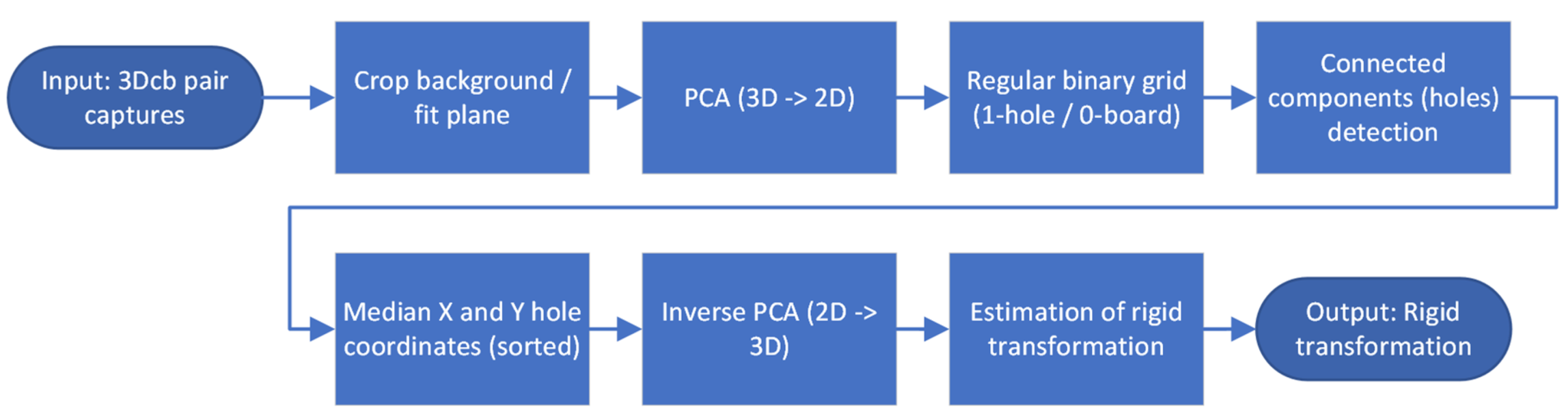
| Algorithm 1. MATLAB pseudocode to calculate the rigid transformation between two 3D scanning systems from a pair of 3D checkerboard captures. |
| Pc2 %point cloud from capture of 3Dcb from system 2 pc1_ref %point cloud from system 1 (reference coordinate system) function Checkerboards3d_estimateT(pc2, pc1_ref) % remove background pc2_noBackground = abs(pc2-distEstimation) <= eps pc1_noBackground = abs(pc1_ref-distEstimation) <= eps for pc = pc2_noBackground, pc1_noBackground do % fit plane, do PCA to transform from 3D into 2D planeModel = pcfitplane(pc) [pcaPlane,coeff,mu] = pca(planeModel) % create regular binary grid for [x,y] = min(pcaPlane):resolution:max(pcaPlane) point_nn = findNearestNeighbors(pcaPlane, [x,y], 1) if abs(point_nn-[x,y])>resolution zGrid(x,y) = 1 end if end for % detect connected components (holes) CC = bwconncomp(zGrid) % calculate median coordinates of holes, sort them and % use inverse PCA to transform back into 3D Median_cc = median(CC) holeMedians = sort(Median_cc) holeMedians3D = holeMedians * transpose(coeff) + mu end for % estimate the geometric transformation between hole medians from both checkerboards tFormEst = estimateGeometricTransform3D(holeMedians3D_2, holeMedians3D_1,’rigid’) return tFormEst end function |
3. Results
4. Discussion
5. Conclusions
Supplementary Materials
Author Contributions
Funding
Institutional Review Board Statement
Informed Consent Statement
Data Availability Statement
Acknowledgments
Conflicts of Interest
Appendix A

| Author & Reference | Sensor Type | Checkerboard | Multicapture or Single Capture | Texture Required | Code Available |
|---|---|---|---|---|---|
| J. Beltran [15] | LiDAR–camera (stereo, mono) | Calibration target with four round holes andArUco markers | Multicapture | No | Velo2cam |
| G. Yan [16] | LiDAR–camera (mono) | Calibration target with four round holes andcheckerboard pattern | Multicapture | Yes | OpenCalib |
| J. Domhof [17] | Radar–camera (stereo)–LiDAR | Calibration target with four round holes | Multicapture | No | Multi_sensor_ calibration |
| J. Zhang [18] | LiDAR–camera–thermal | 2D checkerboards and 3D checkerboard | Multicapture | Yes | No |
| J. Rangel [19] | Thermal–RGB-D camera | 3D checkerboard | Multicapture | Yes | No |
| K. Skala [20] | Thermal–RGB-D camera | 3D checkerboard | Multicapture | Yes | No |
| Proposed | Depth cameras (Structured light–active stereo–ToF) | 3D checkerboard | Single capture | No | Extrinsic3D Calibration |
| Author and Reference | Sensor Type | Toolbox Name | Operating System–Platform |
|---|---|---|---|
| C. Guindel [28] | LiDAR–stereo | Velo2cam | ROS |
| J. Beltran [15] | LiDAR–camera (stereo, mono) | Velo2cam | ROS |
| R. Unnikrishnan [29] | Camera–LiDAR | LCCT | MATLAB |
| A. Geiger [30] | LiDAR–ToF–Camera (stereo) | LIBCBDETECT | MATLAB |
| G. Yan [31] | LiDAR–camera (mono) | OpenCalib | C++ |
| G. Yan [16] | LiDAR–camera (mono) | OpenCalib | C++ |
| J. Domhof [17] | Radar–camera (stereo)–LiDAR | Multi_sensor_calibration | ROS |
| J. K. Huang [32] | LiDAR–camera (mono) | extrinsic_lidar_camera_calibration | MATLAB |
| A. Dhall [33] | LiDAR–camera (mono, stereo) | lidar_camera_calibration | ROS |
| M. Velas [34] | LiDAR–RGB camera (mono) | but_calibration_camera_velodyne | ROS |
| L. Yin [35] | LiDAR–camera (mono) | multimodal_data_studio | MATLAB |
| P. C. Su [36] | RGB-D cameras | RGBD_CameraNetwork_Calibration | C++ |
| Proposed (Kaiser et al.) | Depth cameras (Structured light–active stereo–ToF) | Extrinsic3DCalibration | MATLAB |
| Author and Reference | Sensor Type | Checkerboard or Scene | Features | Multicapture or Single Capture | Publication Type | Texture Required | Autonomous Driving |
|---|---|---|---|---|---|---|---|
| M. Lindner [37] | PMD ToF–RGB camera (mono) | 2D checkerboard | Plane | MC | C | Yes | X |
| S. Fuchs [38] | ToF | 2D checkerboard | Plane (dark–bright) | MC | C | Yes | X |
| J. Zhu [39] | ToF–passive stereo | 2D checkerboard | Plane (dark–bright) | MC | C | Yes | X |
| H. Zou [40] | Laser profilers | Spheres | Spheres | MC | J | No | No |
| J. Schmidt [41] | ToF | Scene | Point correspondence | MC | C | Intensity | X |
| H. Lee [42] | LiDAR | Planar objects from Scene | Plane correspondence | MC | J | No | Yes |
| S. Chen [43] | LiDAR | Spheres | Sphere center and corresponding points | MC | J | No | Yes |
| C. Guindel [28] | LiDAR–stereo | Calibration target with four round holes | Plane, Circles and point correspondence | MC | C | No | Yes |
| J. Beltran [15] | LiDAR–camera (stereo–mono) | Calibration target with four round holes and ArUco markers | Plane, Circles, point correspondence and ArUco markers | MC | J | No–Yes | Yes |
| Y. M. Kim [44] | ToF–camera (stereo) | 2D checkerboard | Corners | MC | C | Yes | No |
| D. Scaramuzza [45] | LiDAR–camera (mono) | Scene | Natural features | MC | C | Yes | Yes |
| R. Unnikrishnan [29] | Camera–LiDAR | 2D checkerboard | Corners and Plane | MC | O | Yes | Yes |
| Q. Zhang [46] | Camera–LiDAR | 2D checkerboard | Plane | MC | C | Yes | Yes |
| A. Geiger [30] | LiDAR–ToF–Camera (stereo) | Multiple 2D checkerboards | Corners and Planes | SC (Multitarget) | C | Yes | X |
| L. Zhou [47] | Stereo–LiDAR | 2D checkerboard | Plane and Line correspondences | MC | C | Yes | Yes |
| Q. Wang [48] | LiDAR–camera | 3x 2D checkerboard | Planes and Corners | MC | J | Yes | Yes |
| S. Verma [49] | Camera (mono)–LiDAR | 2D checkerboard | Planes and Corners | MC | C | Yes | Yes |
| J. Ou [50] | LiDAR–camera (mono, stereo) | 2D checkerboard | Corners, intensity and Plane | MC | J | Yes | Yes |
| X. Gong [51] | LiDAR–camera | Trihedron | Planes | MC | J | Yes | Yes |
| G. Yan [31] | LiDAR–camera (mono) | Calibration target with four round holes and checkerboard pattern | Circles and Corners | MC | O | Yes | Yes |
| Y. An [52] | LiDAR–camera (mono) | 2D checkerboard | Plane and Corners | MC | J | Yes | Yes |
| S. A. Rodriguez F. [53] | LiDAR–camera (mono) | Circle | Circle | MC | C | Yes | Yes |
| G. Yan [16] | LiDAR–camera (mono) | Calibration target with four round holes and checkerboard pattern | Circles and Corners | MC | J | Yes | Yes |
| J. Zhang [18] | LiDAR–camera–thermal | 2D checkerboards and 3D checkerboard | Corners and circles | MC | C | Yes | Yes |
| J. Domhof [17] | Radar–camera (stereo)–LiDAR | Calibration target with four round holes | Circles | MC | C | No | Yes |
| E. S. Kim [54] | LiDAR–camera (mono) | 2D checkerboard | Corners and Plane | MC | J | Yes | Yes |
| Y. Wang [55] | LiDAR–camera (mono) | Review | n.a. | n.a. | C | n.a. | Yes |
| A. Khurana [56] | LiDAR–camera (mono, stereo) | Review | n.a. | n.a. | J | n.a. | Yes |
| J. Nie [57] | LiDAR–camera (mono) | Review | n.a. | n.a. | C | n.a. | Yes |
| D. J. Yeong [58] | LiDAR–camera (mono, stereo) | Review | n.a. | n.a. | J | n.a. | Yes |
| P. An [59] | LiDAR–camera (mono) | 2D checkerboards | Corners and Plane | Multitarget | J | Yes | Yes |
| J. Persic [60] | LiDAR–Radar | Triangular trihedralcorner reflector | Triangle and Plane | MC | C | No | Yes |
| J. K. Huang [32] | LiDAR–camera (mono) | Planar square targets | Plane and Corners | MC | J | Yes | Yes |
| A. Dhall [33] | LiDAR–camera (mono, stereo) | Planar boards with ArUco tags | Corners and Edges | MC | O | Yes | Yes |
| M. Velas [34] | LiDAR–RGB camera (mono) | Calibration target with four round holes | Circles and edges | SC | C | Yes | Yes |
| L. Yin [35] | LiDAR–camera (mono) | 2D checkerboard | Corners and plane | MC | J | Yes | Yes |
| H. Liu [61] | RGB-D cameras | Spheres | Sphere center | MC | J | Yes | X |
| A. Perez-Yus [62] | RGB camera–Depth camera | Line observations | Lines | MC | J | Yes | Yes |
| C. Daniel Herrera [63] | RGB camera–Depth camera | 2D checkerboard | Corners and Plane | MC | J | Yes | No |
| J. Chaochuan [64] | RGB-D cameras | Calibration tower | Circles | MC | J | Yes | No |
| Y. C. Kwon [65] | RGB-D cameras | Circles and spheres | Circles | MC | J | Yes | No |
| Z. Wu [66] | RGB camera–Depth camera | 3D Checkerboard | Corners | MC | C | Yes | No |
| R. Avetisyan [67] | RGB-D cameras | 2D Checkerboard and Markers | Corners and Markers | MC | C | Yes | No |
| R. S. Pahwa [68] | PMD depth camera (ToF) | 2D checkerboard | Corners and Plane | MC | C | Yes | No |
| D. S. Ly [69] | Mono cameras | Scene | Lines | MC | J | Yes | No |
| W. Li [70] | 3D scanner–optical tracker | 3D benchmark | Point set (ICP) | MC | J | No | No |
| M. Ruan [71] | Depth cameras | Spherical target | Shere center | MC | C | No | No |
| N. Eichler [72] | Depth cameras | human motion | Skeletal joints | MC | J | No | No |
| B. S. Park [73] | RGB-D cameras | 3D Charuco board | QR code and feature points | MC | J | Yes | No |
| J. Guan [74] | Mono cameras | Spheres | Sphere center | MC | J | Yes | No |
| P. C. Su [36] | RGB-D cameras | Spheres | Sphere center | MC | J | Yes | No |
| J. Rangel [19] | Thermal–RGB-D camera | 3D checkerboard | Circular holes | MC | C | Yes | No |
| K. Skala [20] | Thermal–RGB-D camera | 3D checkerboard | Rectangular holes | MC | J | Yes | No |
| Proposed (Kaiser et al.) | Depth cameras (Structured light–active stereo–ToF) | 3D checkerboard | Rectangular holes and Plane | SC | J | No | No |
References
- Bassani, T.; Stucovitz, E.; Galbusera, F.; Brayda-Bruno, M. Is rasterstereography a valid noninvasive method for the screening of juvenile and adolescent idiopathic scoliosis? Eur. Spine J. 2019, 28, 526–535. [Google Scholar] [CrossRef] [PubMed]
- Marin, L.; Lovecchio, N.; Pedrotti, L.; Manzoni, F.; Febbi, M.; Albanese, I.; Patanè, P.; Pellino, V.C.; Vandoni, M. Acute Effects of Self-Correction on Spine Deviation and Balance in Adolescent Girls with Idiopathic Scoliosis. Sensors 2022, 22, 1883. [Google Scholar] [CrossRef] [PubMed]
- Paśko, S.; Glinkowski, W. Combining 3D Structured Light Imaging and Spine X-ray Data Improves Visualization of the Spinous Lines in the Scoliotic Spine. Appl. Sci. 2021, 11, 301. [Google Scholar] [CrossRef]
- Ledwoń, D.; Danch-Wierzchowska, M.; Bugdol, M.; Bibrowicz, K.; Szurmik, T.; Myśliwiec, A.; Mitas, A.W. Real-Time Back Surface Landmark Determination Using a Time-of-Flight Camera. Sensors 2021, 21, 6425. [Google Scholar] [CrossRef] [PubMed]
- Albert, J.A.; Owolabi, V.; Gebel, A.; Brahms, C.M.; Granacher, U.; Arnrich, B. Evaluation of the Pose Tracking Performance of the Azure Kinect and Kinect v2 for Gait Analysis in Comparison with a Gold Standard: A Pilot Study. Sensors 2020, 20, 5104. [Google Scholar] [CrossRef] [PubMed]
- Xu, Z.; Zhang, Y.; Fu, C.; Liu, L.; Chen, C.; Xu, W.; Guo, S. Back Shape Measurement and Three-Dimensional Reconstruction of Spinal Shape Using One Kinect Sensor. In Proceedings of the 2020 IEEE 17th International Symposium on Biomedical Imaging (ISBI), Iowa City, IA, USA, 3–7 April 2020; pp. 745–749. [Google Scholar] [CrossRef]
- Rehouma, H.; Noumeir, R.; Essouri, S.; Jouvet, P. Advancements in Methods and Camera-Based Sensors for the Quantification of Respiration. Sensors 2020, 20, 7252. [Google Scholar] [CrossRef]
- Kokabu, T.; Kawakami, N.; Uno, K.; Kotani, T.; Suzuki, T.; Abe, Y.; Maeda, K.; Inage, F.; Ito, Y.M.; Iwasaki, N.; et al. Three-dimensional depth sensor imaging to identify adolescent idiopathic scoliosis: A prospective multicenter cohort study. Sci. Rep. 2019, 9, 9678. [Google Scholar] [CrossRef]
- Nam, K.W.; Park, J.; Kim, I.Y.; Kim, K.G. Application of Stereo-Imaging Technology to Medical Field. Healthc. Informatics Res. 2012, 18, 158–163. [Google Scholar] [CrossRef]
- Zhang, W.; Sun, X.; Yu, Q. Moving Object Detection under a Moving Camera via Background Orientation Reconstruction. Sensors 2020, 20, 3103. [Google Scholar] [CrossRef]
- Chapel, M.-N.; Bouwmans, T. Moving objects detection with a moving camera: A comprehensive review. Comput. Sci. Rev. 2020, 38, 100310. [Google Scholar] [CrossRef]
- Liu, T.; Liu, Y. Moving Camera-Based Object Tracking Using Adaptive Ground Plane Estimation and Constrained Multiple Kernels. J. Adv. Transp. 2021, 2021, 8153474. [Google Scholar] [CrossRef]
- Jung, S.; Cho, Y.; Lee, K.; Chang, M. Moving Object Detection with Single Moving Camera and IMU Sensor using Mask R-CNN Instance Image Segmentation. Int. J. Precis. Eng. Manuf. 2021, 22, 1049–1059. [Google Scholar] [CrossRef]
- Jung, S.; Cho, Y.; Kim, D.; Chang, M. Moving Object Detection from Moving Camera Image Sequences Using an Inertial Measurement Unit Sensor. Appl. Sci. 2020, 10, 268. [Google Scholar] [CrossRef]
- Beltran, J.; Guindel, C.; de la Escalera, A.; Garcia, F. Automatic Extrinsic Calibration Method for LiDAR and Camera Sensor Setups. IEEE Trans. Intell. Transp. Syst. 2022, 23, 17677–17689. [Google Scholar] [CrossRef]
- Yan, G.; Liu, Z.; Wang, C.; Shi, C.; Wei, P.; Cai, X.; Ma, T.; Liu, Z.; Zhong, Z.; Liu, Y.; et al. OpenCalib: A multi-sensor calibration toolbox for autonomous driving. Softw. Impacts 2022, 14, 100393. [Google Scholar] [CrossRef]
- Domhof, J.; Kooij, J.F.P.; Gavrila, D.M. A Joint Extrinsic Calibration Tool for Radar, Camera and Lidar. IEEE Trans. Intell. Veh. 2021, 6, 571–582. [Google Scholar] [CrossRef]
- Zhang, J.; Siritanawan, P.; Yue, Y.; Yang, C.; Wen, M.; Wang, D. A Two-step Method for Extrinsic Calibration between a Sparse 3D LiDAR and a Thermal Camera. In Proceedings of the 2018 15th International Conference on Control, Automation, Robotics and Vision, ICARCV 2018, Singapore, 18–21 November 2018; pp. 1039–1044. [Google Scholar] [CrossRef]
- Rangel, J.; Soldan, S.; Kroll, A. 3D Thermal Imaging: Fusion of Thermography and Depth Cameras. e-J. Nondestruct. Test. 2015, 20. Available online: https://www.ndt.net/search/docs.php3?id=17665 (accessed on 16 September 2023).
- Skala, K.; Lipić, T.; Sovic, I.; Gjenero, L.; Grubisic, I. 4D thermal imaging system for medical applications. Period. Biol. 2011, 113, 407–416. [Google Scholar]
- 3D Camera|MotionCam|Photoneo Focused on 3D. Available online: https://www.photoneo.com/motioncam-3d (accessed on 2 September 2023).
- TIDA-00254 Reference Design|TI.com. Available online: https://www.ti.com/tool/TIDA-00254 (accessed on 2 September 2023).
- BoofCV. Available online: https://boofcv.org/index.php?title=Main_Page (accessed on 2 September 2023).
- Marshall, G.F.; Stutz, G.E. Handbook of Optical and Laser Scanning; Taylor & Francis: Abingdon, UK, 2018. [Google Scholar]
- DLPLCR4500EVM Evaluation Board|TI.com. Available online: https://www.ti.com/tool/DLPLCR4500EVM (accessed on 2 September 2023).
- VGA Industriekamera USB 3.0 Vision MV-CA023-10UM. Available online: https://www.maxxvision.com/produkte/kameras/usb3-vision-kameras/220/mv-ca023-10um (accessed on 2 September 2023).
- Kaiser, M.; Brusa, T.; Wyss, M.; Ćuković, S.; Bertsch, M.; Taylor, W.R.; Koch, V.M. Minimal Required Resolution to Capture the 3D Shape of the Human Back—A Practical Approach. Sensors 2023, 23, 7808. [Google Scholar] [CrossRef]
- Guindel, C.; Beltran, J.; Martin, D.; Garcia, F. Automatic extrinsic calibration for lidar-stereo vehicle sensor setups. In Proceedings of the IEEE Conference on Intelligent Transportation Systems, ITSC, Maui, HI, USA, 4–7 November 2018; pp. 1–6. [Google Scholar] [CrossRef]
- Unnikrishnan, R. Fast Extrinsic Calibration of a Laser Rangefinder to a Camera. 2005. Available online: www.cs.cmu.edu/ (accessed on 10 August 2023).
- Geiger, A.; Moosmann, F.; Car, Ö.; Schuster, B. Automatic camera and range sensor calibration using a single shot. In Proceedings of the 2012 IEEE International Conference on Robotics and Automation, Saint Paul, MN, USA, 14–18 May 2012; pp. 3936–3943. [Google Scholar] [CrossRef]
- Yan, G.; He, F.; Shi, C.; Wei, P.; Cai, X.; Li, Y. Joint Camera Intrinsic and LiDAR-Camera Extrinsic Calibration. February 2022. Available online: https://arxiv.org/abs/2202.13708v3 (accessed on 10 August 2023).
- Huang, J.K.; Grizzle, J.W. Improvements to Target-Based 3D LiDAR to Camera Calibration. IEEE Access 2020, 8, 134101–134110. [Google Scholar] [CrossRef]
- Dhall, A.; Chelani, K.; Radhakrishnan, V.; Krishna, K.M. LiDAR-Camera Calibration Using 3D-3D Point Correspondences. May 2017. Available online: https://arxiv.org/abs/1705.09785v1 (accessed on 10 August 2023).
- Velas, M.; Spanel, M.; Materna, Z.; Herout, A. Calibration of RGB Camera With Velodyne LiDAR. Available online: http://hdl.handle.net/11025/26408 (accessed on 28 February 2024).
- Yin, L.; Luo, B.; Wang, W.; Yu, H.; Wang, C.; Li, C. CoMask: Corresponding Mask-Based End-to-End Extrinsic Calibration of the Camera and LiDAR. Remote Sens. 2020, 12, 1925. [Google Scholar] [CrossRef]
- Su, P.-C.; Shen, J.; Xu, W.; Cheung, S.-C.S.; Luo, Y. A Fast and Robust Extrinsic Calibration for RGB-D Camera Networks. Sensors 2018, 18, 235. [Google Scholar] [CrossRef]
- Lindner, M.; Kolb, A. Calibration of the intensity-related distance error of the PMD TOF-camera. In Proceedings of the Intelligent Robots and Computer Vision XXV: Algorithms, Techniques, and Active Vision, Boston, MA, USA, 9–11 September 2007; Volume 6764, p. 67640W. [Google Scholar] [CrossRef]
- Fuchs, S.; Hirzinger, G. Extrinsic and depth calibration of ToF-cameras. In Proceedings of the 26th IEEE Conference on Computer Vision and Pattern Recognition, CVPR, Anchorage, AK, USA, 24–26 June 2008. [Google Scholar] [CrossRef]
- Zhu, J.; Wang, L.; Yang, R.; Davis, J. Fusion of time-of-flight depth and stereo for high accuracy depth maps. In Proceedings of the 26th IEEE Conference on Computer Vision and Pattern Recognition, CVPR, Anchorage, AK, USA, 24–26 June 2008. [Google Scholar] [CrossRef]
- Zou, H.; Xia, R.; Zhao, J.; Zhang, T.; Zhang, T.; Chen, Y.; Fu, S. Extrinsic calibration method for 3D scanning system with four coplanar laser profilers. Meas. Sci. Technol. 2022, 34, 015906. [Google Scholar] [CrossRef]
- Schmidt, J.; Brückner, M.; Denzler, J. Extrinsic self-calibration of time-of-flight cameras using a combination of 3D and intensity descriptors. In Proceedings of the VMV 2011—Vision, Modeling and Visualization, Berlin, Germany, 4–6 October 2011; pp. 269–276. [Google Scholar] [CrossRef]
- Lee, H.; Chung, W. Extrinsic Calibration of Multiple 3D LiDAR Sensors by the Use of Planar Objects. Sensors 2022, 22, 7234. [Google Scholar] [CrossRef] [PubMed]
- Chen, S.; Liu, J.; Wu, T.; Huang, W.; Liu, K.; Yin, D.; Liang, X.; Hyyppä, J.; Chen, R. Extrinsic Calibration of 2D Laser Rangefinders Based on a Mobile Sphere. Remote. Sens. 2018, 10, 1176. [Google Scholar] [CrossRef]
- Kim, Y.M.; Chan, D.; Theobalt, C.; Thrun, S. Design and calibration of a multi-view TOF sensor fusion system. In Proceedings of the 2008 IEEE Computer Society Conference on Computer Vision and Pattern Recognition Workshops, CVPR Workshops, Anchorage, AK, USA, 24–26 June 2008. [Google Scholar] [CrossRef]
- Scaramuzza, D.; Harati, A.; Siegwart, R. Extrinsic self calibration of a camera and a 3D laser range finder from natural scenes. In Proceedings of the IEEE International Conference on Intelligent Robots and Systems, San Diego, CA, USA, 29 October–2 November 2007; pp. 4164–4169. [Google Scholar] [CrossRef]
- Zhang, Q.; Pless, R. Extrinsic calibration of a camera and laser range finder (improves camera calibration). In Proceedings of the 2004 IEEE/RSJ International Conference on Intelligent Robots and Systems (IROS), Sendai, Japan, 28 September–2 October 2004; Volume 3, pp. 2301–2306. [Google Scholar] [CrossRef]
- Zhou, L.; Li, Z.; Kaess, M. Automatic Extrinsic Calibration of a Camera and a 3D LiDAR Using Line and Plane Correspondences. In Proceedings of the IEEE International Conference on Intelligent Robots and Systems, Madrid, Spain, 1–5 October 2018; pp. 5562–5569. [Google Scholar] [CrossRef]
- Wang, Q.; Yan, C.; Tan, R.; Feng, Y.; Sun, Y.; Liu, Y. 3d-Cali: Automatic Calibration for Camera and Lidar Using 3d Checkerboard. Measurement 2022, 203, 111971. [Google Scholar] [CrossRef]
- Verma, S.; Berrio, J.S.; Worrall, S.; Nebot, E. Automatic extrinsic calibration between a camera and a 3D Lidar using 3D point and plane correspondences. In Proceedings of the 2019 IEEE Intelligent Transportation Systems Conference, ITSC 2019, Auckland, New Zealand, 27–30 October 2019; pp. 3906–3912. [Google Scholar] [CrossRef]
- Ou, J.; Huang, P.; Zhou, J.; Zhao, Y.; Lin, L. Automatic Extrinsic Calibration of 3D LIDAR and Multi-Cameras Based on Graph Optimization. Sensors 2022, 22, 2221. [Google Scholar] [CrossRef]
- Gong, X.; Lin, Y.; Liu, J. 3D LIDAR-Camera Extrinsic Calibration Using an Arbitrary Trihedron. Sensors 2013, 13, 1902–1918. [Google Scholar] [CrossRef]
- An, Y.; Li, B.; Wang, L.; Zhang, C.; Zhou, X. Calibration of a 3D laser rangefinder and a camera based on optimization solution. J. Ind. Manag. Optim. 2021, 17, 427–445. [Google Scholar] [CrossRef]
- Rodriguez, F.S.A.; Frémont, V.; Bonnifait, P. Extrinsic calibration between a multi-layer lidar and a camera. In Proceedings of the IEEE International Conference on Multisensor Fusion and Integration for Intelligent Systems, Seoul, Republic of Korea, 20–22 August 2008; pp. 214–219. [Google Scholar] [CrossRef]
- Kim, E.-S.; Park, S.-Y. Extrinsic Calibration between Camera and LiDAR Sensors by Matching Multiple 3D Planes. Sensors 2019, 20, 52. [Google Scholar] [CrossRef]
- Wang, Y.; Li, J.; Sun, Y.; Shi, M. A Survey of Extrinsic Calibration of LiDAR and Camera. Proceedings of 2021 International Conference on Autonomous Unmanned Systems (ICAUS 2021), Changsha, China, 24–26 September 2021; Lecture Notes in Electrical Engineering. Springer: Singapore, 2022; Volume 861, pp. 933–944. [Google Scholar]
- Khurana, A.; Nagla, K.S. Extrinsic Calibration Methods for Laser Range Finder and Camera: A Systematic Review. Mapan-J. Metrol. Soc. India 2021, 36, 669–690. [Google Scholar] [CrossRef]
- Nie, J.; Pan, F.; Xue, D.; Luo, L. A Survey of Extrinsic Parameters Calibration Techniques for Autonomous Devices. In Proceedings of the 33rd Chinese Control and Decision Conference, CCDC 2021, Kunming, China, 22–24 May 2021; pp. 3543–3548. [Google Scholar] [CrossRef]
- Yeong, D.J.; Velasco-hernandez, G.; Barry, J.; Walsh, J. Sensor and Sensor Fusion Technology in Autonomous Vehicles: A Review. Sensors 2021, 21, 2140. [Google Scholar] [CrossRef] [PubMed]
- An, P.; Ma, T.; Yu, K.; Fang, B.; Zhang, J.; Fu, W.; Ma, J. Geometric calibration for LiDAR-camera system fusing 3D-2D and 3D-3D point correspondences. Opt. Express 2020, 28, 2122–2141. [Google Scholar] [CrossRef] [PubMed]
- Persic, J.; Markovic, I.; Petrovic, I. Extrinsic 6DoF calibration of 3D LiDAR and radar. In Proceedings of the 2017 European Conference on Mobile Robots, ECMR 2017, Paris, France, 6–8 September 2017. [Google Scholar] [CrossRef]
- Liu, H.; Qu, D.; Xu, F.; Zou, F.; Song, J.; Jia, K. Approach for accurate calibration of RGB-D cameras using spheres. Opt. Express 2020, 28, 19058–19073. [Google Scholar] [CrossRef] [PubMed]
- Perez-Yus, A.; Fernandez-Moral, E.; Lopez-Nicolas, G.; Guerrero, J.J.; Rives, P. Extrinsic Calibration of Multiple RGB-D Cameras From Line Observations. IEEE Robot. Autom. Lett. 2018, 3, 273–280. [Google Scholar] [CrossRef]
- Herrera, C.D.; Kannala, J.; Heikkilä, J. Joint depth and color camera calibration with distortion correction. IEEE Trans. Pattern Anal. Mach. Intell. 2012, 34, 2058–2064. [Google Scholar] [CrossRef] [PubMed]
- Chaochuan, J.; Ting, Y.; Chuanjiang, W.; Binghui, F.; Fugui, H. An extrinsic calibration method for multiple RGB-D cameras in a limited field of view. Meas. Sci. Technol. 2020, 31, 045901. [Google Scholar] [CrossRef]
- Kwon, Y.C.; Jang, J.W.; Hwang, Y.; Choi, O. Multi-Cue-Based Circle Detection and Its Application to Robust Extrinsic Calibration of RGB-D Cameras. Sensors 2019, 19, 1539. [Google Scholar] [CrossRef]
- Wu, Z.; Zhu, W.; Zhu, Q. Semi-Transparent Checkerboard Calibration Method for KINECTrs Color and Depth Camera. In Proceedings of the 2018 International Conference on Network, Communication, Computer Engineering (NCCE 2018), Chongqing, China, 26–27 May 2018; pp. 141–148. [Google Scholar] [CrossRef]
- Avetisyan, R.; Willert, M.; Ohl, S.; Staadt, O. Calibration of Depth Camera Arrays. 2014. Available online: https://ep.liu.se/ecp/106/006/ecp14106006.pdf (accessed on 28 February 2024).
- Pahwa, R.S.; Do, M.N.; Ng, T.T.; Hua, B.S. Calibration of depth cameras using denoised depth images. In Proceedings of the 2014 IEEE International Conference on Image Processing, ICIP 2014, Paris, France, 27–30 October 2014; pp. 3459–3463. [Google Scholar] [CrossRef]
- Ly, D.S.; Demonceaux, C.; Vasseur, P.; Pégard, C. Extrinsic calibration of heterogeneous cameras by line images. Mach. Vis. Appl. 2014, 25, 1601–1614. [Google Scholar] [CrossRef]
- Li, W.; Fan, J.; Li, S.; Tian, Z.; Zheng, Z.; Ai, D.; Song, H.; Yang, J. Calibrating 3D Scanner in the Coordinate System of Optical Tracker for Image-To-Patient Registration. Front. Neurorobotics 2021, 15, 636772. [Google Scholar] [CrossRef]
- Ruan, M.; Huber, D. Extrinsic Calibration of 3D Sensors Using a Spherical Target. In Proceedings of the 2014 2nd International Conference on 3D Vision, Tokyo, Japan, 8–11 December 2014. [Google Scholar]
- Eichler, N.; Hel-Or, H.; Shimshoni, I. Spatio-Temporal Calibration of Multiple Kinect Cameras Using 3D Human Pose. Sensors 2022, 22, 8900. [Google Scholar] [CrossRef] [PubMed]
- Park, B.S.; Kim, W.; Kim, J.K.; Kim, D.W.; Seo, Y.H. Iterative extrinsic calibration using virtual viewpoint for 3D reconstruction. Signal Process. 2022, 197, 108535. [Google Scholar] [CrossRef]
- Guan, J.; Deboeverie, F.; Slembrouck, M.; Van Haerenborgh, D.; Van Cauwelaert, D.; Veelaert, P.; Philips, W. Extrinsic Calibration of Camera Networks Using a Sphere. Sensors 2015, 15, 18985–19005. [Google Scholar] [CrossRef] [PubMed]


| Use Case | Posture–Movement | Systems |
|---|---|---|
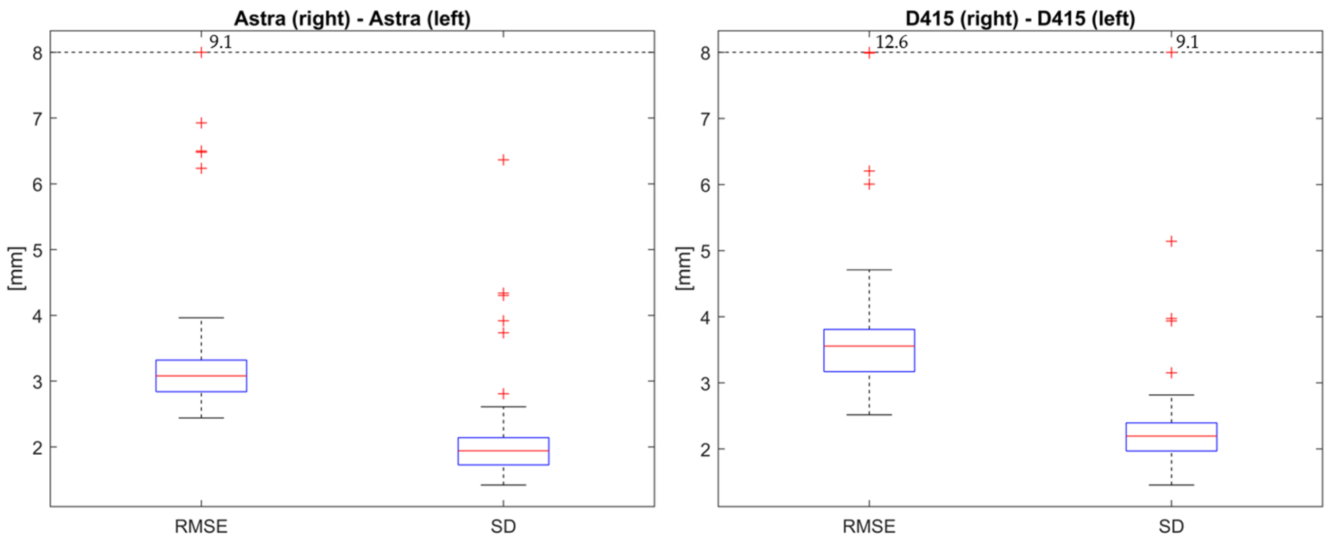
| 1: Register captures from left and right camera pairs | Static standing upright | 2× Orbbec Astra, 2× Intel D415 |
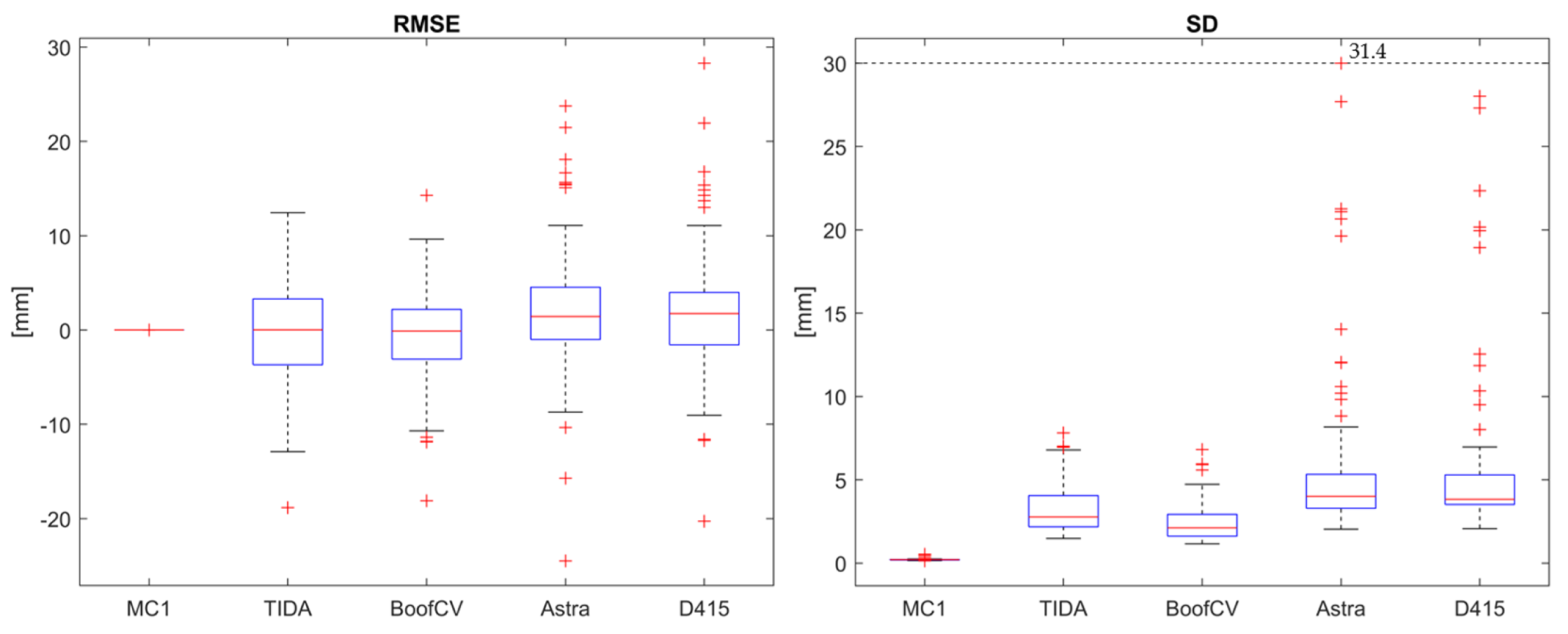
| 2: Register captures to its reference capture | Static standing upright | TIDA-00254, BoofCV, 2× Orbbec Astra, 2× Intel D415, Photoneo MotionCam-3D |
| 3: Register captures from above and behind | Dynamic forward bending | 2× Photoneo MotionCam-3D |
| MotionCam 1 | TIDA-00254 | BoofCV | 2× Orbbec Astra Mini | 2× Intel D415 |
|---|---|---|---|---|
| 0 mm (0.2 mm) | 0.02 mm (2.9 mm) | 0.1 mm (2.1 mm) | 1.5 mm (4.0 mm) | 1.7 mm (3.9 mm) |
| System | Methodology | Resolution | Accuracy |
|---|---|---|---|
| Photoneo MotionCam-3D M+ | SL | 1680 × 1200 and 1120 × 800 | error <0.3 mm at 0.9 m |
| TIDA-00254 | SL | 912 × 1140 and 1920 × 1200 | error ~1 mm at 1 m |
| BoofCV | AS | 912 × 1140 and 1920 × 1200 | error ~1 mm at 1 m |
| Intel D415 | AS | 1280 × 720 | error <2% up to 2 m |
| Orbbec Astra Mini | SL | 640 × 480 | error <3 mm at 1 m |
Disclaimer/Publisher’s Note: The statements, opinions and data contained in all publications are solely those of the individual author(s) and contributor(s) and not of MDPI and/or the editor(s). MDPI and/or the editor(s) disclaim responsibility for any injury to people or property resulting from any ideas, methods, instructions or products referred to in the content. |
© 2024 by the authors. Licensee MDPI, Basel, Switzerland. This article is an open access article distributed under the terms and conditions of the Creative Commons Attribution (CC BY) license (https://creativecommons.org/licenses/by/4.0/).
Share and Cite
Kaiser, M.; Brusa, T.; Bertsch, M.; Wyss, M.; Ćuković, S.; Meixner, G.; Koch, V.M. Extrinsic Calibration for a Modular 3D Scanning Quality Validation Platform with a 3D Checkerboard. Sensors 2024, 24, 1575. https://doi.org/10.3390/s24051575
Kaiser M, Brusa T, Bertsch M, Wyss M, Ćuković S, Meixner G, Koch VM. Extrinsic Calibration for a Modular 3D Scanning Quality Validation Platform with a 3D Checkerboard. Sensors. 2024; 24(5):1575. https://doi.org/10.3390/s24051575
Chicago/Turabian StyleKaiser, Mirko, Tobia Brusa, Martin Bertsch, Marco Wyss, Saša Ćuković, Gerrit Meixner, and Volker M. Koch. 2024. "Extrinsic Calibration for a Modular 3D Scanning Quality Validation Platform with a 3D Checkerboard" Sensors 24, no. 5: 1575. https://doi.org/10.3390/s24051575
APA StyleKaiser, M., Brusa, T., Bertsch, M., Wyss, M., Ćuković, S., Meixner, G., & Koch, V. M. (2024). Extrinsic Calibration for a Modular 3D Scanning Quality Validation Platform with a 3D Checkerboard. Sensors, 24(5), 1575. https://doi.org/10.3390/s24051575