2.1. Principle of SHMF-MZI
In this study, the single mode fiber (SMF), step-index multimode fiber (SIMMF) and graded-index multimode fiber (GIMMF) employed in the creation of the SHMF-MZI were sourced from Yangtze Optical Fiber Company. The structure of the SHMF-MZI is illustrated in
Figure 1, which is constructed using a section of GIMMF spliced with two sections of SIMMF on both of its ends, and the diameter of the GIMMF is smaller than that of the SIMMF. When light transmits from the input-SMF into SIMMF1, due to the mismatch between the fiber core diameters, higher-order core modes are stimulated in SIMMF1. When light transmits to the GIMMF, due to the mismatching of the mode fields between GIMMF and SIMMF1, part of the light is coupled to the core modes of the GIMMF, and the rest is coupled to the cladding modes of the GIMMF and finally recoupled into the high-order core modes of SIMMF2. Light in the core of the GIMMF is propagated along the sinusoidal curve-like trajectory and also finally recoupled into the core of SIMMF2, thus finally forming an in-line optical fiber interferometer called SHMF-MZI. The specially designed structure of the SHMF-MZI could achieve extremely high curvature sensitivity within a small range of bends [
27].
The transmission of the SHMF-MZI sensor can be given by the following:
where
is the output light intensity,
and
are the light intensity of the core and cladding modes of the GIMMF, respectively,
and
are the effective refractive indices of the core and cladding of the GIMMF, respectively,
is the length of the GIMMF, and
is the wavelength.
The free spectral range (
FSR) of the SHMF-MZI sensor is given by the following:
where ∆
n is the effective refractive index difference between the core mode and cladding mode of the GIMMF. The normalized extinction ratio of the SHMF-MZI sensor can be expressed as follows:
2.2. Simulation and Optimization of SHMF-MZI
In order to determine the structural parameters of the SHMF-MZI sensor to achieve a desirable transmission spectrum that is suitable for the application of RR and HR measurement, the simulation is carried out using the Beam Propagation Method (BPM) in Rsoft 2018 software. The effect of the length of the SIMMF and GIMMF on the transmission spectrum of the SHMF-MZI is investigated separately using the control variable approach. The structural parameters of the optical fiber used in this work are shown in
Table 1.
In the simulation, the length of the GIMMF is fixed at 2 cm, and the length of the SIMMF is set to be 0, 0.5, 1, 1.5, 2, and 2.5 mm, respectively, to compute the spectra of the SHMF-MZI in the wavelength range from 1250 nm to 1650 nm. The results are shown in
Figure 2a. It can be seen that the length of the SIMMF has strong influences on the transmission spectrum. When the length of the SIMMF is 0 mm, that is, SMF is directly fused to the GIMMF, the interference spectrum does not appear, and the transmission spectrum is close to a straight line. It is because the SIMMF plays a decisive role, which enables the GIMMF to stimulate the higher-order transmission modes. On the contrary, when the length of the SIMMF exceeds 0 mm and gradually increases, the FSR of the transmission spectrum tends to decrease, leading the peaks of the spectrum to become more and more dense. Considering the overall uniformity of the transmission spectra as well as the compactness of the sensor as a whole, the length of the SIMMF is designed as 2 mm.
Subsequently, the length of the SIMMF is fixed at 2 mm, and the characteristics of the transmission spectrum are simulated under the condition that the length of the GIMMF is 1 cm, 2 cm, 5 cm, 10 cm, 20 cm, and 50 cm, respectively, and the results are shown in
Figure 2b. It can be seen that the FSR of the transmission spectrum becomes smaller with the increase in the length of the GIMMF, and when the length of the GIMMF exceeds 2 cm, the spectrum becomes more and more dense, and the visibility of the stripes decreases obviously. Therefore, based on the above simulation results, the lengths of SIMMF and GIMMF for the SHMF-MZI sensor are chosen to be 2 mm and 2 cm, respectively, for the subsequent fabrication and experiments.
2.3. SHMF-MZI-Based Microbend Deformer Sensor
The microbend deformer can make the optical fiber bend regularly to achieve intensity demodulation, which is also suitable for the SHMF-MZI sensor. In the microbend deformer, the SHMF-MZI sensor experiences multi-segment bending as a result of applied forces, which effectively enhances the pressure sensitivity of the sensor. The transmission coefficient of light in the SHMF-MZI sensor is the function of pressure ∆F; by extracting the intensity change in the output light, the force information received by the sensor can be demodulated. A typical microbend deformer transducer is sawtooth-shaped with two main parameters, including microbend spacing
and the number of microbend spacings
N. For GIMMF, there is an optimal microbend spacing
for the microbend deformer given by [
18] the following:
where
a is the radius of the fiber core,
n is the refractive index of the fiber core, and
N.A. is the numerical aperture of the fiber. When
satisfies Equation (4), the transmission mode of the SHMF-MZI sensor reaches full coupling, and the microbend loss and sensitivity reach the maximum. Moreover, the sensitivity of the fiber optic microbend sensor increases with the number of microbend
N [
25,
26]. Therefore, it is anticipated that the sensing region of the fiber optic sensor, which is the GIMMF, is fully covered by the microbend deformer.
The schematic diagram of the SHMF-MZI-based microbend sensor is shown in
Figure 3a. The microbend deformer was fabricated by many sawtooth units pasted on the cover material with strong glue, and each unit was produced by injecting the silicone tube with UV glue, which was then cured to a solid state under a UV light. The optimal microbend spacing is 1.11 mm as calculated by Equation (4). For the purpose of fabrication accuracy, we set the diameter of the silicone tube to be 1 mm; that is, the microbend spacing
was 1 mm. Since the length of the GIMMF was designed as 2 cm, the number of microbend
N was calculated to be 18. Considering that the microbend spacing changes with the change in elastic material for most of the knitted microbend deformer [
19], in this work, the silicone tubes were attached to the back side of an inelastic Velcro with a strong adhesive, and then the SHMF-MZI sensor was attached directly to the belt using the inelastic Velcro, which made the belt easy to clean and replace. In addition, a piece of inelastic material was sewn into the belt, which would ensure that the belt could be freely stretched without affecting the sensing area. The top view and side view of the SHMF-MZI-based microbend deformer sensor are shown in
Figure 3b,c, respectively.
It has been proven previously that the interference intensity of the SHMF-MZI sensor is nearly independent of the temperature [
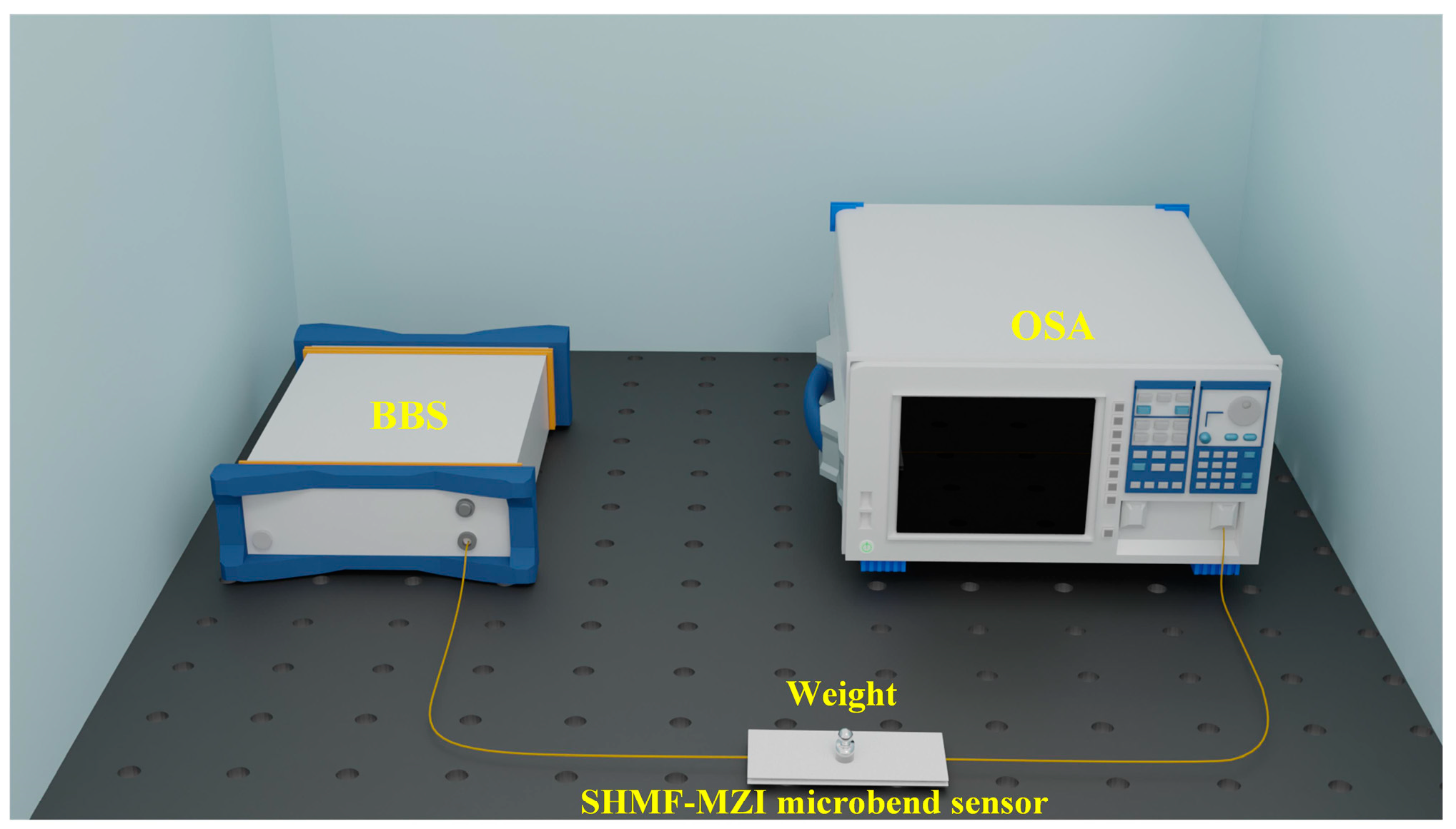
27]. The microbend deformer used in this work has a very low thermal conductivity coefficient. Consequently, the influence of temperature on the SHMF-MZI microsensor can be neglected. In order to analyze the response of the SHMF-MZI-based microbend sensor to micro-pressure, experiments were conducted by adding different standard micro-pressures to the sensor. As shown in
Figure 4, light emitted from a broadband light source (BBS, CONQUER ASE 1528 nm–1610 nm) passes through the SHMF-MZI microbend sensor, and the spectra are recorded by an optical spectral analyzer (OSA, AQ6370D, 600–1700 nm). Weights of 0–7 g corresponding to pressures of 0–0.0686 N, with a step size of 1 g, were placed on the SHMF-MZI sensor in turn.
Figure 5a shows the transmission spectrum of the SHMF-MZI sensor before and after encapsulation with the microbend deformer. It can be seen that the transmission spectrum of the SHMF-MZI sensor after encapsulation is better than that before encapsulation. The FSR of the interference spectrum is nearly unchanged while the visibility of the interference fringes is significantly improved, which can be attributed to the fact that the microbend deformer has improved the coupling efficiency of the SHMF-MZI.
Figure 5b,c show the transmission spectrum and the corresponding intensity near a wavelength of 1590 nm under different pressures, respectively, indicating that the intensity at around 1590 nm almost linearly varies with the pressure and the pressure sensitivity is ~98 dB/N, which is about 327, 778, and 34 times higher than that of FBGs [
28], plastic optical fibers [
29], and thermoplastic polyurethane optical fiber [
30], respectively. Therefore, the proposed SHMF-MZI-based microbend sensor is highly sensitive to micro-pressure and very suitable for detecting vital signal parameters such as HR, RR, BCG, etc.


 ,
, 


