Communication

Design and Preliminary Ground Experiment for Deployable Sunshade Structures of a Modular Space Telescope

1
Changchun Institute of Optics, Fine Mechanics and Physics, Chinese Academy of Sciences, Changchun 130033, China
2
Chinese Academy of Sciences Key Laboratory of On-Orbit Manufacturing and Integration for Space Optics System, Changchun 130033, China
3
University of Chinese Academy of Sciences, Beijing 100049, China
*
Author to whom correspondence should be addressed.
Sensors 2024, 24(7), 2280; https://doi.org/10.3390/s24072280
Submission received: 21 February 2024 / Revised: 28 March 2024 / Accepted: 1 April 2024 / Published: 3 April 2024
(This article belongs to the Section Sensors Development)

Abstract

:
On-orbit assembling space telescope (OAST) is one of the most feasible methods to implement a large-scale space telescope. Unlike a monolithic space telescope (such as Hubble Space Telescope, HST) or a deployable space telescope (such as James Webb Space Telescope, JWST), OAST can be assembled in the spatial environment. To ensure proper telescope performance, OAST must be equipped with a large deployable sunshade. In order to verify the technology of the OAST, the authors propose a modular space telescope on the China Space Station (CSS) and design a deployable sunshade. The deployable mechanism of the sunshade is made up of a radial deployable mechanism and an axial deployable mechanism. The paper describes the overall design approach, the key component technologies, and the design and preliminary testing of a part of the deployable sunshade assembly.

1. Introduction

Space telescopes play an important role in astronomical research. They are the key platforms for the astronomy study. According to the optical principle, increasing the optical aperture can significantly increase the observation angle resolution. To meet the growing demands of multiple applications, larger-aperture space telescopes need to be built in the future. A simple way to increase the optical aperture is to make the primary mirror bigger. One way is to design an on-orbit assembling space telescope (OAST).
The Next Generation Space Telescope started in 1996, and in 2002, it was renamed the James Webb Space Telescope (JWST) [1]. It could compress its space by folding the primary mirror, second mirror, sunshade, and so on into the Ariane V ECA fairing and deployed in the space. The primary mirror diameter of the JWST is 6.5 m. The next space telescope, such as LUVOIR [2], has the same way to fold the telescope into the SLS. But this approach uses a single launching vehicle, which has a certain carrying capacity.
The OAST was first presented by NASA around the early 2000s. It has a modular design and can be modularly manufactured on the ground and modularly launched into space. The OAST can be launched by using several carrier rockets, unlike the deployable space telescope that only uses one rocket.
Several assembling space telescope projects have been put forward, as shown in Figure 1. In 1999, Boeing had a space telescope project named the Next, Next Generation Space Telescope (NNGST) [3]. Then, the autonomously assembled space telescope (AAST) was brought out in 2003 [4]. NASA and GFSC introduced the Thirty Meter Space Telescope (TMST) in 2006 [5] and the Modular Assembled Space Telescope (MAST) in 2013 [6]. The evolvable space telescope (EST) project was planned, with three assembly stages [7,8]. In 2015, JPL brought out the robotically assembled, modular space telescope (RAMST) [9]. CIOMP is coming up with a 10-m-diameter OAST [10,11].
To verify the technology of the OAST, several small OASTs have been brought out, such as the assembly of a large modular optical space telescope (ALMOST) in 2008 [12], Optical Testbed and Integration on ISS eXperiment (OPTIIX) in 2012 [13], and modular orbital demonstration of an evolvable space telescope (MODEST) in 2015 [8,14], as shown in Figure 2. The small OASTs described above are both planned for the International Space Station.
In addition to the telescopes mentioned above, antennas also can be deployed in space. Antennas with a diameter of 100 m and larger were designed in the 1970s [15,16,17], as well as other antennas, like Sunflower [18], MEA [18], SSDA [19], and EGS [20]. But they have a paraboloid surface, not suitable for the OAST.
At present, the China Space Station (CSS) has completed several launches. Tianhe core module, Wentian lab module, and Mengtian lab module have completed joint work. In the future, the China Space Station Telescope (CSST) will be launched into space. Soon, the OAST technology can be verified in space.
The deployable sunshade is a key technology for the OAST. The telescopes need to have a large deployable sunshade structure design, such as on the JWST [21,22,23,24], LUVOIR [2], and IXO [25]. In this paper, we demonstrate the design and analysis of the sunshade of the OAST on the CSS. We hope some of the analysis results will be helpful to the design of the OAST and other space telescopes.

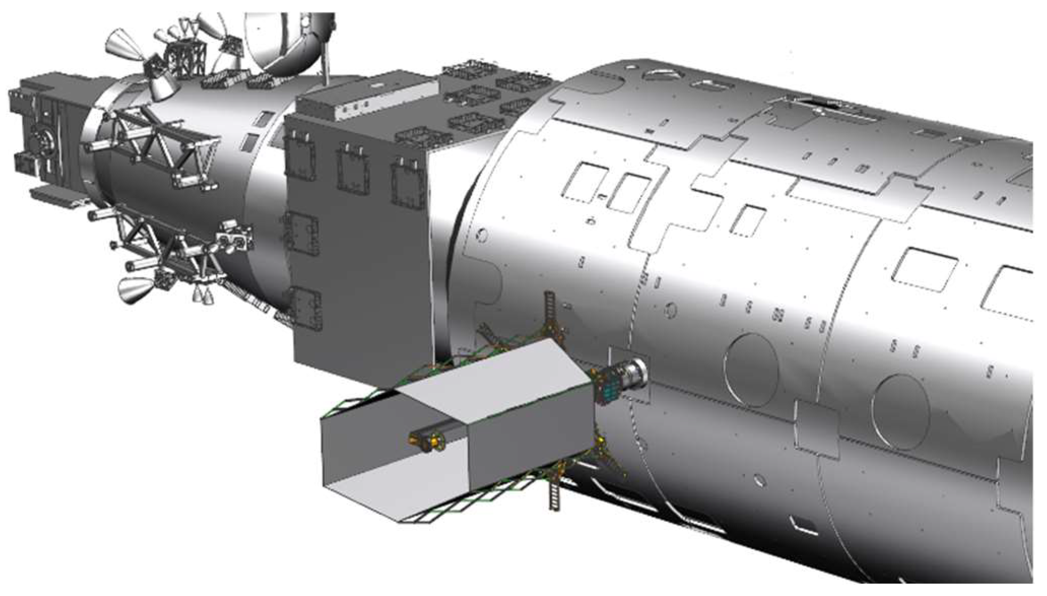
2. The Modular Space Telescope on CSS

2.1. The Top Design of the Modular Space Telescope on CSS

Like the OPTIIX and MODEST projects, the modular space telescope modules can be transported to the CSS by cargo ships. The modular space telescope can be assembled by robotic arms or astronauts. The modular space telescope consists of several modular components, such as an optical module, submirror module, second mirror module, sunshade, etc. The modular space telescope’s working state is shown in Figure 3.
Based on existing engineering experience, such as JWST, to reduce the impact of external vibration, the sunshade is mounted on the bus. There are also vibration isolation devices between the optical system and the bus. To keep the quality of the imaging, the space telescope modules need vibration isolation devices. However, the sunshade cannot be put on the CSS, so the vibration isolation devices can only be put at the bottom of the optical system, which reduces the external vibration effects from the sunshade and CSS as much as possible.

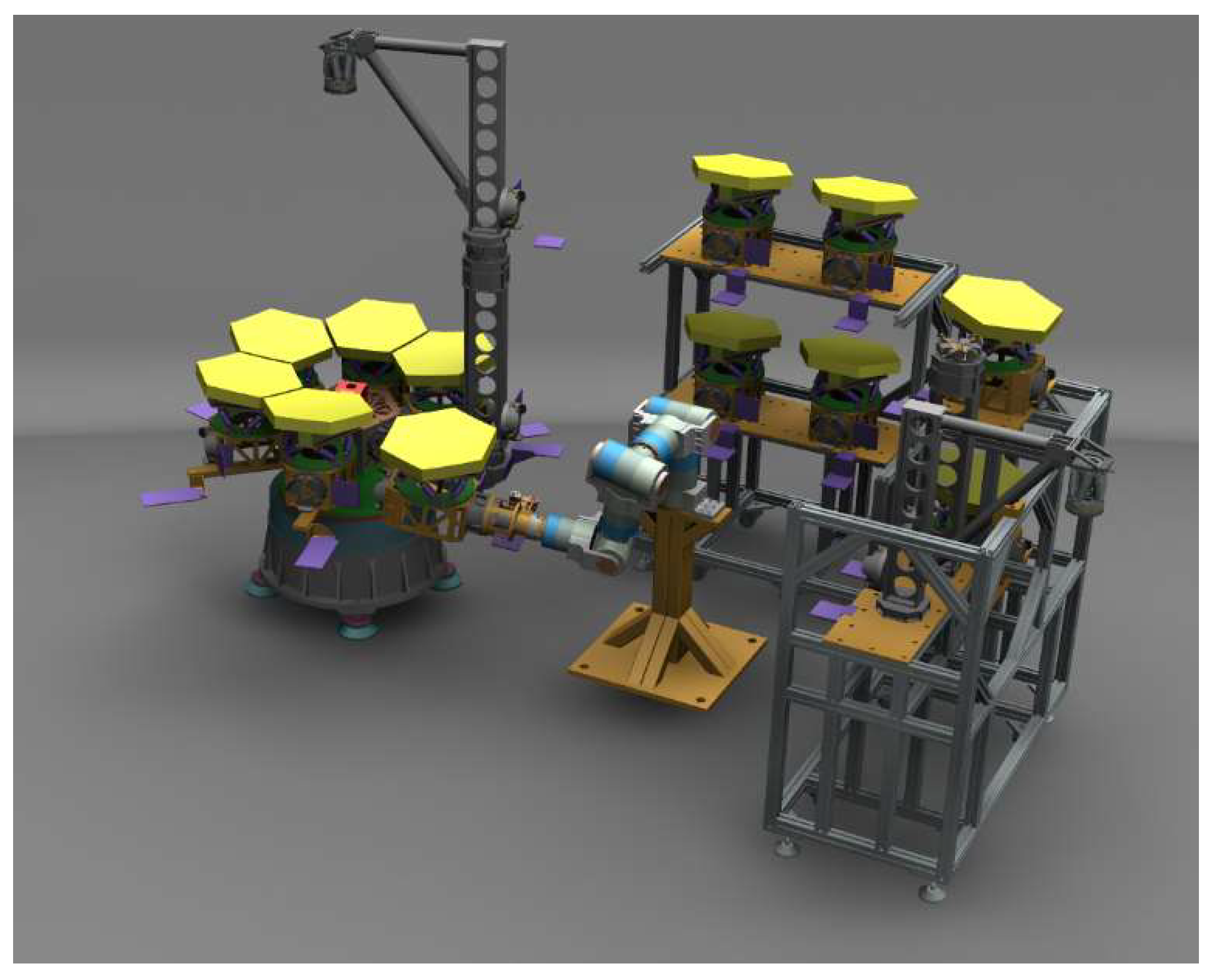
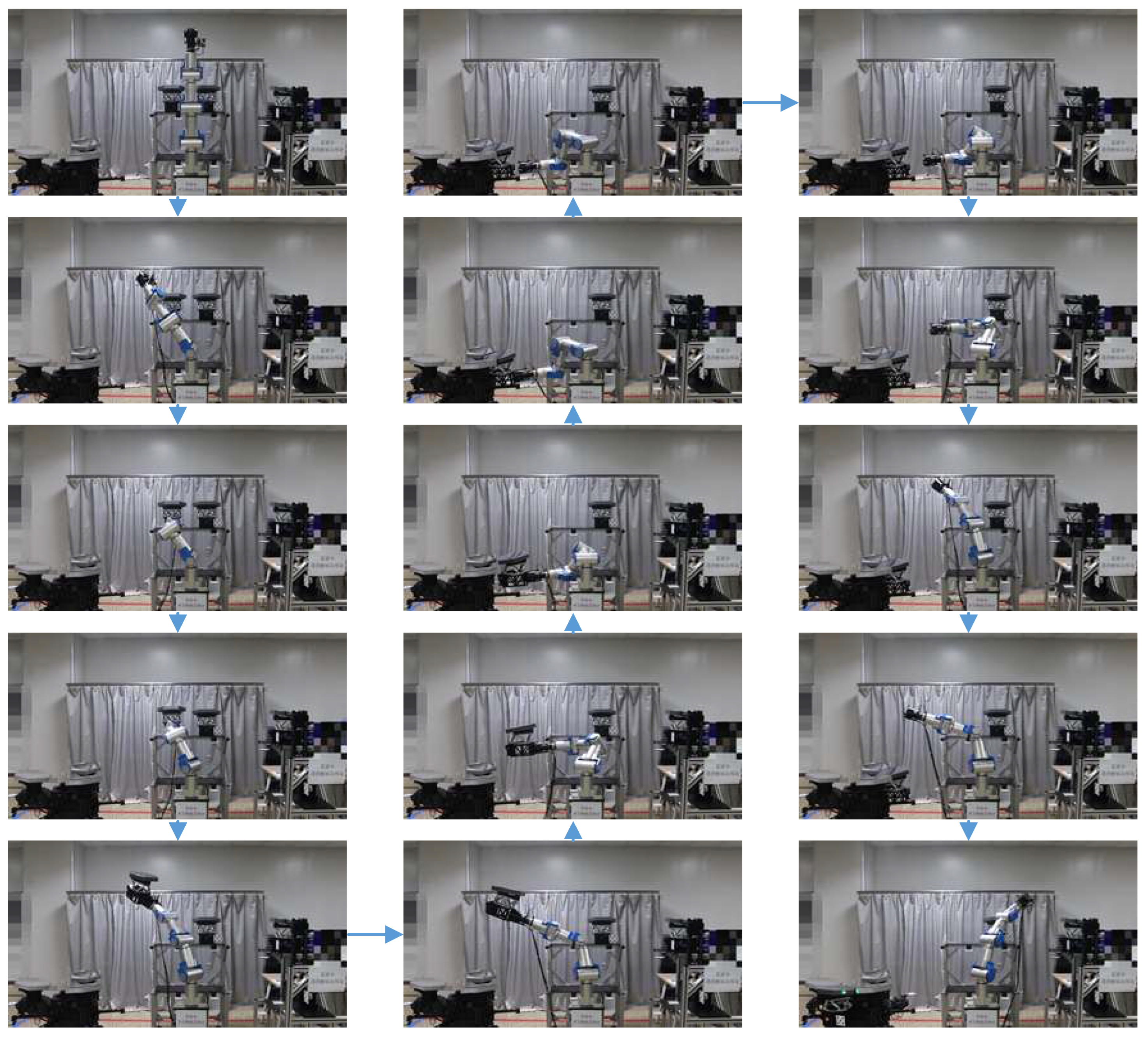
2.2. The Ground Experiment of the Robot Assembly Process

In the early work, the assembly test of the prototype of the ground telescope was carried out. The whole test system is composed of a structural prototype, a submirror module, a second mirror module, and a robotic arm.
Through 3D software (UG 10), we simulate the assembly process and determine the relative position relationship of the robotic arm and telescope prototype. The assembly simulation is shown in Figure 4. Then, the actual assembly test is carried out, and the assembly is shown in Figure 5.
In the process of the submirror assembly, the robotic arm first grabs the submirror. According to the spatial trajectory planning, the robotic arm moves the submirror to the installation location. Using the hand-eye camera, which is at the end of the robotic arm, the robotic arm completes the approach to the telescope prototype. When the submirror interface moves to the capture range, the docking interface is actively locked and the robotic arm moves through the force sensor. After the prototype lock is completed, the robotic arm unlocks the submirror and moves away from the telescope prototype. The telescope prototype will then rotate to prepare for the next assembly.

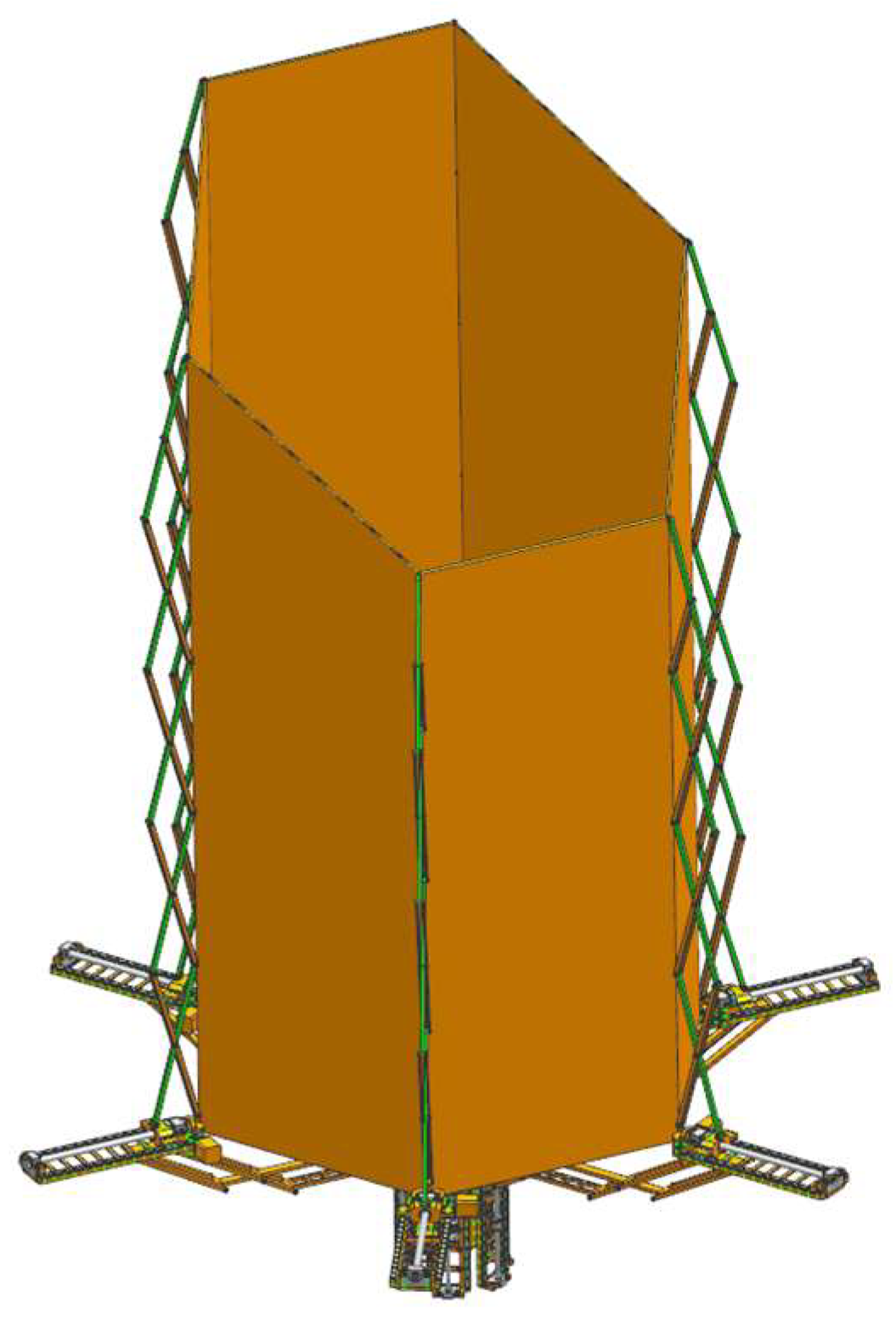
3. The Design of the Deployable Sunshade Assembly Structures

3.1. Requirements

After the optical elements are manufactured, the space telescope modules are transported to the CSS by cargo ships. Astronauts will check modules and complete parts of the assembly work in the CSS. The main optical machine module can be moved to the outer load of the CSS cabin by the robotic arm.
To verify the assembly process of the module, the module installation is completed by using the robotic arm. In the assembly process, the sunshade needs to provide sufficient space for the robotic arm. After the assembly, the sunshade is expanded. Then, the active optical adjustment and optical imaging work are carried out.
The sunshade is required throughout the whole process as follows:
(1)
The sunshade module needs to meet the volume, weight, and other limitation requirements of the package when the sunshade is in the cargo ship.
(2)
The sunshade module needs to meet the volume and other limitation requirements of the CSS.
(3)
The sunshade module needs to meet the volume, weight, and other limitation requirements when the sunshade moves from the inside of the CSS to the outside of the CSS.
(4)
The sunshade module needs to provide sufficient volume for the robotic arm during the assembly process.
(5)
The sunshade module needs to meet the function of keeping out the stray light.
(6)
The sunshade module’s dynamic responses should not affect the imaging of the optical system.
To meet the sixth requirement, vibration isolation devices are installed between the sunshade and the main optical machine. Besides the sixth requirement, other requirements can be reduced to the constraint requirements for the sunshade module in the folded state and deployable state, which can be addressed by a good structural and mechanism design.

3.2. Structure Design

The deployable mechanism of the sunshade is made up of a radial deployable mechanism and an axial deployable mechanism. The radial deployable mechanism achieves folding and deployable functions through in-plane rotation. The axial deployable mechanism is a scissor-like element (SLE), which achieves folding and deployment in a straight axial direction.
Because the CSS is in LEO, to effectively block stray light mainly from the sun, the sunshade needs to have a certain angle. Hence, the number of SLEs in the axial deployable mechanism may not be the same.
A single deployable component consists of two sets of driving devices, corresponding to the radial and axial deployable mechanisms. Most of the structures are made of aluminum alloy. Hence, the deployable sunshade assembly structures meet all the requirements proposed in Section 3.1. The next general structure design will adopt a more lightweight structure design.
The deployable sunshade assembly structures are shown in Figure 6, Figure 7 and Figure 8. Figure 6 shows the deployable sunshade assembly structures in the folding state. Figure 7 shows the radial deployable mechanism deployed, and Figure 8 shows the radial and axial deployable mechanisms deployed. To meet the volume and weight requirements of the sunshade, the parameters of the structure need to be adjusted carefully.

3.3. Kinematics Analysis

3.3.1. Radial Deployable Mechanism

The radial deployable mechanism consists of several radial deployable components. A single radial deployable component is shown in Figure 9. There are ten key points of the single radial deployable component, such as points A, B, C, D, E, F, G, H, I, and J. There are six rods, such as rods AC, BD, DE, GH, HJ, and JF. Point C is on the rod BD. Point E is on the rod JF. Point G is on the rod AC. And the point I is on the rod BD. Rods AC, HJ, and DE are in parallel. Rods BD, GH, and JF are in parallel.
The length of AB is lc. The length of AC is lb. The length of BC is la. The length of BD is ld. The length of the CD is ldla. The length of DE is le. The length of EF is lf. The length of GC is lh. The length of GH is lg. The length of the ID is ldla. The length of JE is ldlalg. Hence, we can get the angle between rod BC and rod BA and the angle between rod AB and rod AC, which can be expressed as
cos C B A = l a 2 + l c 2 l b 2 2 l a l c
cos B A C = l b 2 + l c 2 l a 2 2 l b l c
Hence, the ten points’ coordinates can be expressed as
A 0 , l c
B 0 , 0
C l a sin C B A , l a cos C B A
D l d sin C B A , l d cos C B A
E l d sin C B A + l e sin B A C , l d cos C B A + l e cos B A C
F l d sin C B A + l e sin B A C + l f sin C B A , l d cos C B A + l e cos B A C l f cos C B A
G l a sin C B A l h sin B A C , l a cos C B A l h cos B A C
H l a sin C B A l h sin B A C + l g sin C B A , l a cos C B A l h cos B A C l g cos C B A
I l a sin C B A + l g sin C B A , l a cos C B A l g cos C B A
J l a sin C B A + l g sin C B A + l e sin B A C , l a cos C B A l g cos C B A + l e cos B A C

3.3.2. Axial Deployable Mechanism

A single axial deployable component consists of several SLEs. Each SLE is the mechanism are shown in Figure 10. There are five key points of the single SLE, such as points M, N, O, P, and Q. Point O is the midpoint of the rod MQ and rod NP. The length of both MQ and NP is l. The length of both MO and NO is l/2. The distance of MN is x. θ is the angle from MN to MQ. The angle is positive for anticlockwise. Hence, we can get the angle of the NMQ, which can be shown as
cos θ = x l
The point coordinates of the i-th SLE can be expressed as
M i 0 , i 1 l sin θ
N i x , i 1 l sin θ
O i 1 2 x , i 1 2 l sin θ
P i 0 , i l sin θ
Q i x , i l sin θ
The point velocities of the i-th SLE can be expressed as
M ˙ i = 0 , i 1 x l 2 x 2 x ˙
N ˙ i = x ˙ , i 1 x l 2 x 2 x ˙
O ˙ i = 1 2 x ˙ , i 1 2 x l 2 x 2 x ˙
P ˙ i = 0 , i x l 2 x 2 x ˙
Q ˙ i = x ˙ , i x l 2 x 2 x ˙
The point accelerations of the i-th SLE can be expressed as
M ¨ i = 0 , i 1 l 2 l 2 x 2 3 2 x ˙ 2 + x l 2 x 2 x ¨
N ¨ i = x ¨ , i 1 l 2 l 2 x 2 3 2 x ˙ 2 + x l 2 x 2 x ¨
O ¨ i = 1 2 x ¨ , i 1 2 l 2 l 2 x 2 3 2 x ˙ 2 + x l 2 x 2 x ¨
P ¨ i = 0 , i l 2 l 2 x 2 3 2 x ˙ 2 + x l 2 x 2 x ¨
Q ¨ i = x ¨ , i l 2 l 2 x 2 3 2 x ˙ 2 + x l 2 x 2 x ¨
The rotation velocities of the i-th SLE can be expressed as
ω M Q = ω N P = 1 l 2 x 2 x ˙
The rotation accelerations of the i-th SLE can be expressed as
α M Q = α N P = x ¨ l 2 x 2 x x ˙ 2 l 2 x 2 3 2

3.3.3. Structure Parameters
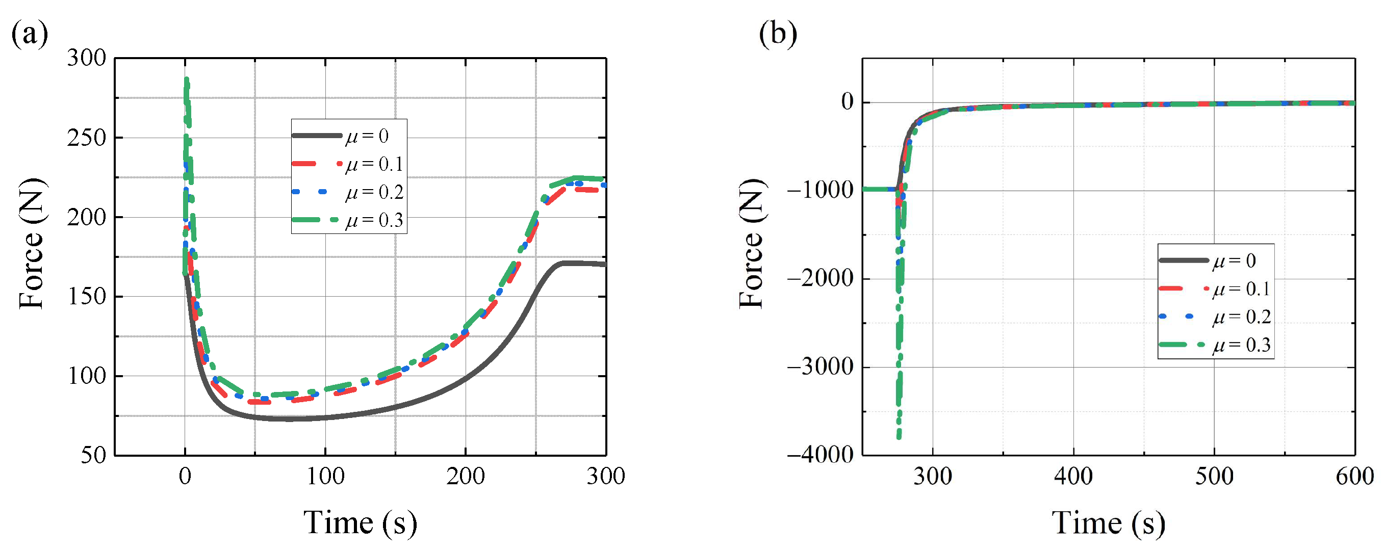
The above equations can be combined to establish the structural kinematics model; the structural boundary constraint equations, such as the constraint boundary equations in the process of axial deployable mechanism, can be established
X M = X P R 0 Y P = Y Q h 0
where R0 indicates the radius of the sunshade inscribed circle, and h0 indicates the height of the sunshade. The constraint boundary equations before the radial deployable process
Y Q 5 l 0 Y Q 6 w 0 × cos 30
where l0 indicates the length of the storage box, and w0 indicates the width of the storage box.
The initial structural parameters are obtained through parameter adjustment. Then, the parameters are adjusted based on the 3D model and corrected if there are structural interferences. Finally, the structural design is obtained as shown in Figure 6, Figure 7 and Figure 8.

3.4. Force Analyses

The sunshade needs to deploy on the CSS. To verify the feasibility of the motion mechanism, it is necessary to conduct force analyses on the deployment mechanism of the sunshade and determine the motor torque. This section mainly analyzes its development along the optical axis direction as an example. The force analysis by formulations provides a preliminary scheme design and uses multi-dynamic software (UG 10) for simulation to get more accurate data.

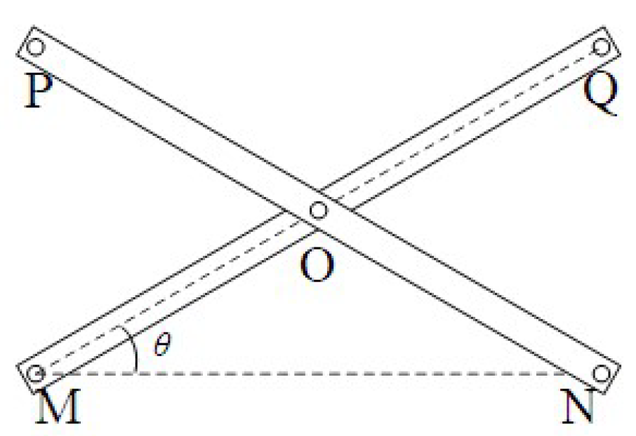
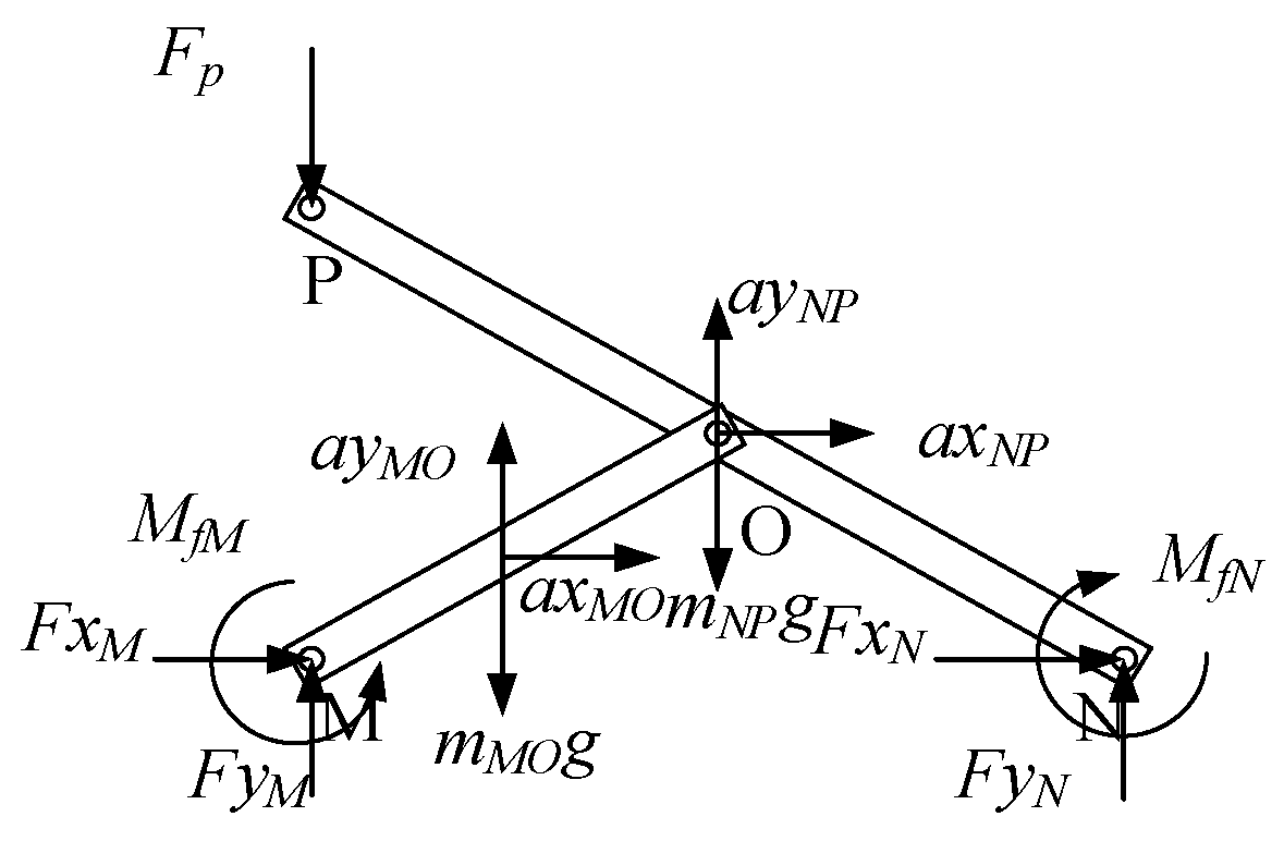
3.4.1. The Force Analysis of the Top SLE

The force analysis of the top SLE is shown in Figure 11 where a possible external force Fp is applied at point P. The force analyses of the rod MO and rod NP are shown in Figure 12. The calculation formulation can be obtained as follows
F x M + F x O = m M O a x M O
F y M + F y O = m M O g + m A C a y M O
F x M F x O 1 4 l sin θ + F y O F y M 1 4 l cos θ + M f M + M f O = J r M O ω M O
F x N F x O = m N P a x N P
F y N F y O F p m N P g = m N P a y N P
F x N 1 2 l sin θ + F y N 1 2 l cos θ + F p 1 2 l cos θ M f O M f N = J r N P ω N P
where, MfM, MfO, and MfN are friction torques caused by friction. They can be calculated by functions as follows
M f M = sgn ω M Q μ F x M 2 + F y M 2 R M f O = sgn ω M Q μ F x O 2 + F y O 2 R M f N = sgn ω M Q μ F x N 2 + F y N 2 R
where μ is the coefficient of friction, and R is the radius of the pin. Hence, we can get the forces of the points M, N, and O, which are FxM, FyM, FxN, FyN, FxO, and FyO.

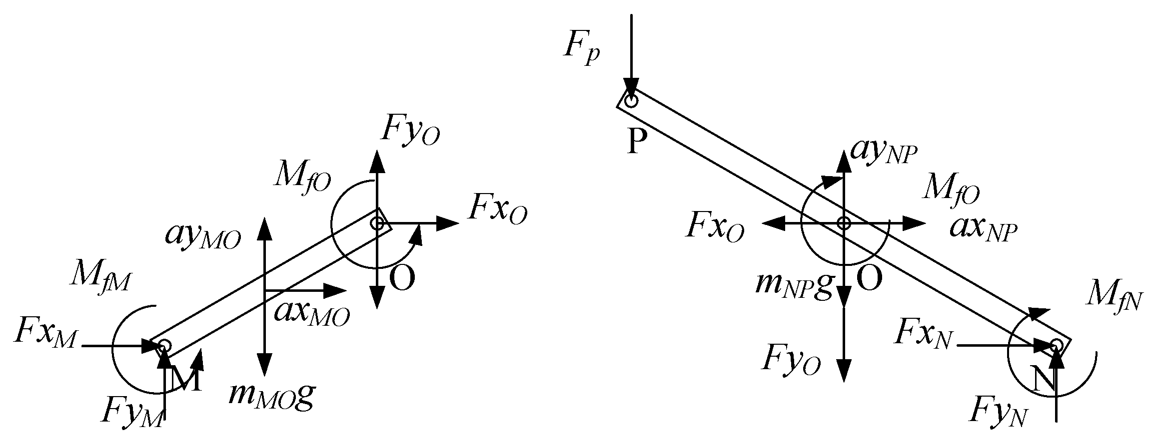
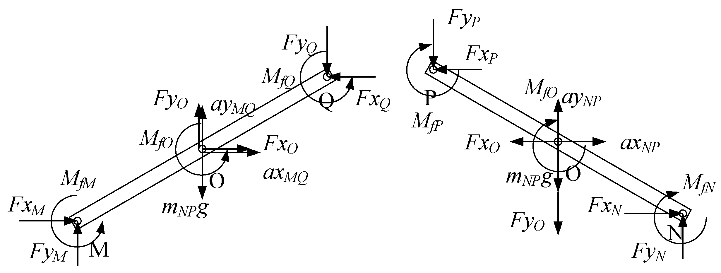
3.4.2. The Force Analysis of the Normal SLE

The force analyses of the rod MQ and the rod NP are shown in Figure 13. The calculation formulation can be obtained as follows
F x M + F x O F x Q = m M Q a x M Q
F y M + F y O F y Q m M Q g = m M Q a y M Q
F x M 1 2 l sin θ F y M 1 2 l cos θ + F x Q 1 2 l sin θ F y Q 1 2 l cos θ + M f M + M f O + M f Q = J r M Q ω M Q
F x N F x O F x P = m N P a x N P
F y N F y O F y P m N P g = m N P a y N P
F x N 1 2 l sin θ + F y N 1 2 l cos θ + F x P 1 2 l sin θ + F y P 1 2 l cos θ M f N M f O M f P = J r N P ω N P
where MfQ and MfP are friction torques caused by friction. They can be calculated by functions as follows
M f P = sgn ω M Q μ F x P 2 + F y P 2 R M f Q = sgn ω M Q μ F x Q 2 + F y Q 2 R
FxP, FyP, FxQ, and FyQ are known quantities. They are reaction forces. Hence, we can get the forces of the points M, N, and O, which are FxM, FyM, FxN, FyN, FxO, and FyO.

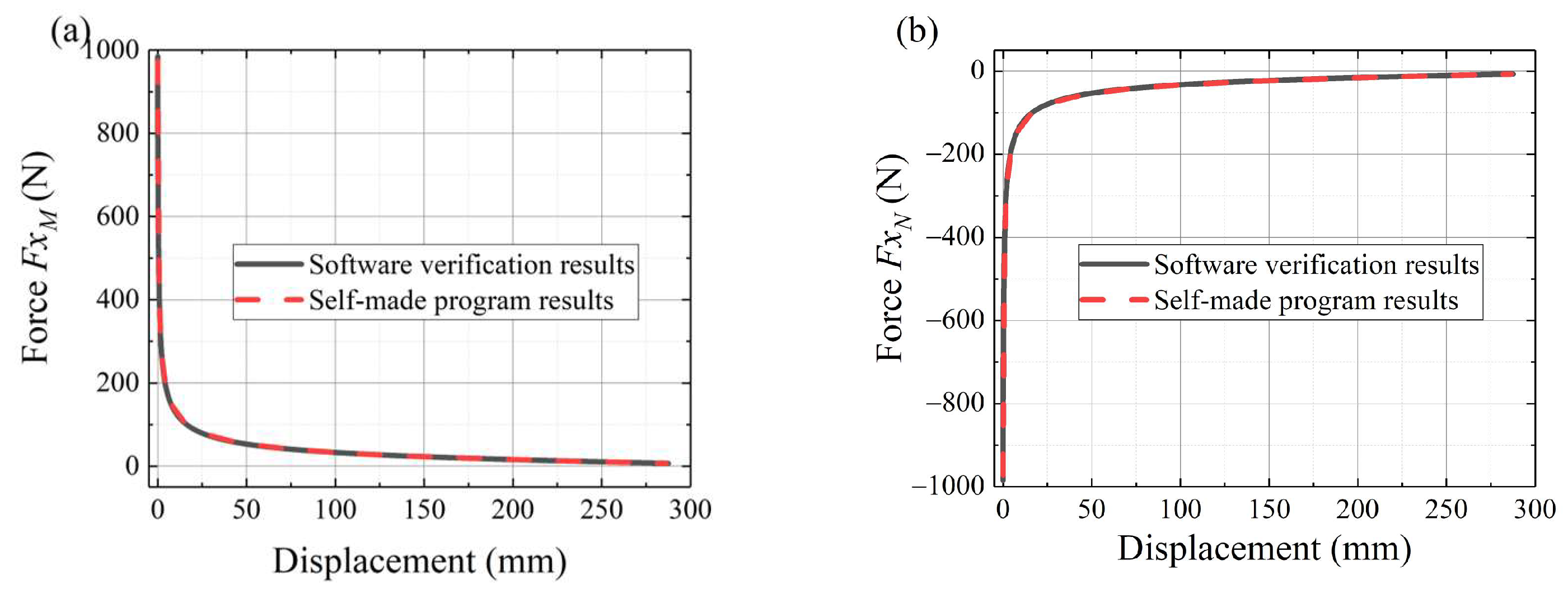
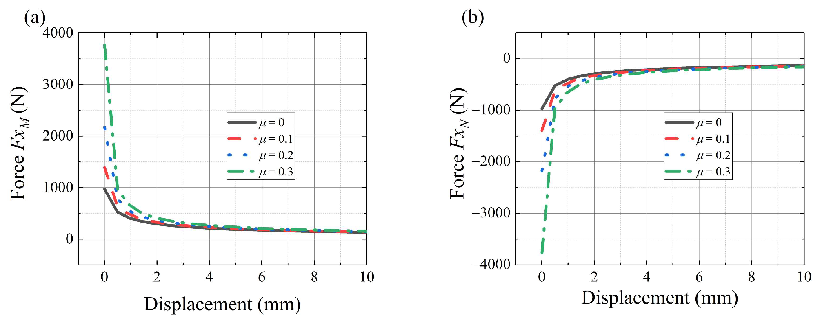
3.4.3. Force Analysis Results

To calculate the forces of point M, point N, and point O, we program according to the above equations. To verify the accuracy of the calculation results, we use multi-body dynamics software for verification. Both models are in the gravity. Figure 14a,b shows the horizontal forces of point M and point N without friction, respectively. The black solid line represents the software verification results. The red dashed line represents the calculation results of the self-made program. It shows that the red line results are consistent with the black line results, which proves the validity of the force analysis. From simulation data and the structure design, the motor torque can be determined.
In practice, the effect of friction can greatly influence the deployable mechanism. The functions above can be used to complete the preliminary design. Figure 15a,b shows the horizontal forces of point M and point N with friction, respectively. It shows different forces with different friction parameters. At the starting position of the movement, the driving force peaks and rapidly decreases. Figure 15 only shows the beginning of the movement.
Multi-body dynamic software is used to finish the dynamic simulation. The motion processes are shown in Figure 16 and Figure 17. The radial deployable motion and the axial deployable motion are completed in turn. Figure 18a,b shows the driving forces of the radial deployable mechanism and the axial deployable mechanism with friction, respectively.
Table 1 shows the peak value of the forces. It shows that the maximum relative error is approximately 3.2% with μ = 0.3. From the multi-body dynamic software solutions, when considering friction with μ = 0.3, the force of the radial deployable increases about 173% from 168 N to 290 N at the beginning and about 132% from 171 N to 225 N, and the force of the axial deployable increase around 395% from 984 N to 3887 N. The friction coefficient is assumed to be 0.3. From simulation data and the structure design, the motor torque can be determined.

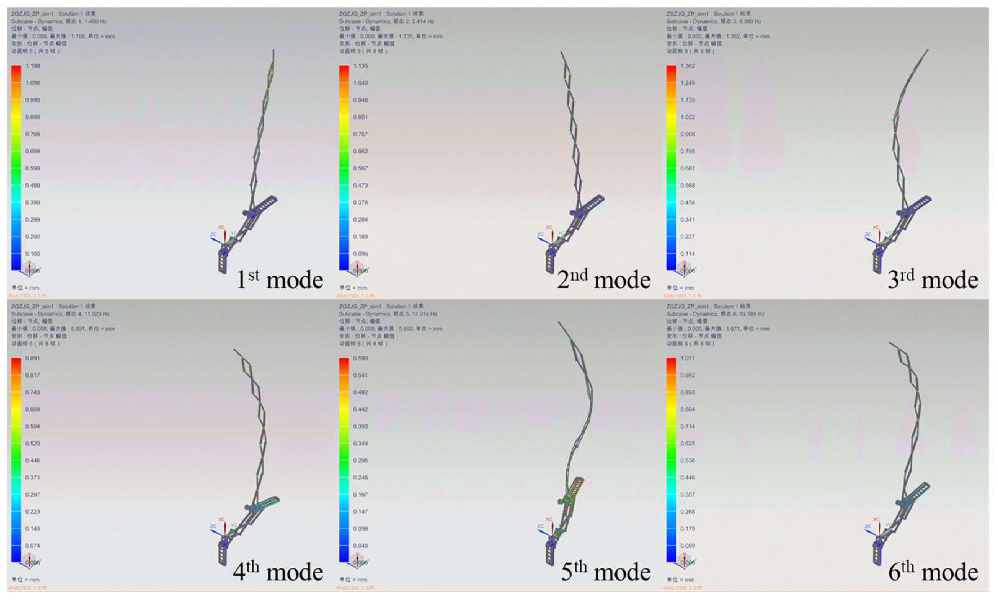
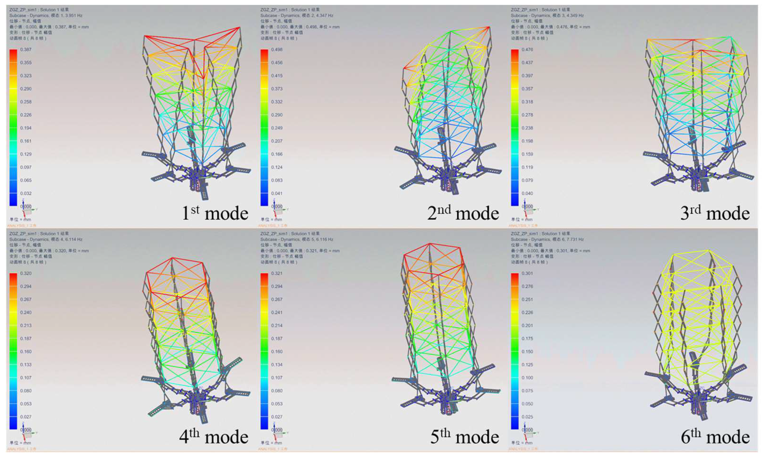
3.5. Vibrational Modes

The vibrational modes of the single deployable component are shown in Figure 19. It shows the first to the sixth mode shapes. The numerical results of the vibrational modes are shown in Table 2. The minimum frequency of the structure is 1.46 Hz. For the 1st mode and 2nd mode, the mode shapes mainly swing in the two horizontal directions, respectively.
The sunshade usually consists of several deployable components. The vibrational modes of the sunshade are shown in Figure 20. It shows the first to the sixth mode shapes. The numerical results of the vibrational modes are shown in Table 2. The minimum frequency of the structure is 3.951 Hz. By increasing the constraints, the 1st mode and 2nd mode frequencies increase. Figure 20 shows more mode shapes—such as the sixth mode is the twisting mode.
The current simulation results show that there should be a vibration isolation device between the telescope optical system and the sunshade. The performance of the vibration isolation device determines the optical system metrics. Also, the natural frequency of the sunshade deployable components can still be improved by structure design, such as the constraints between single components.

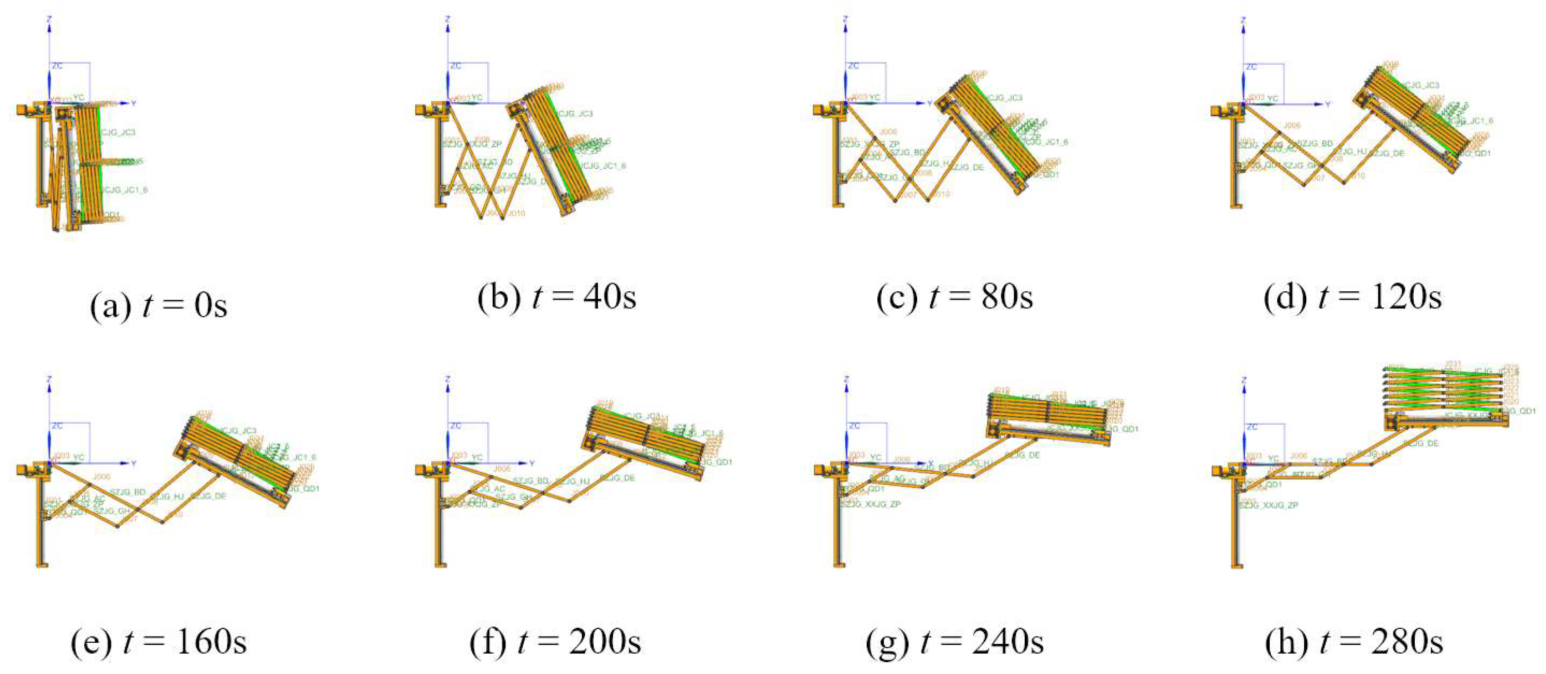
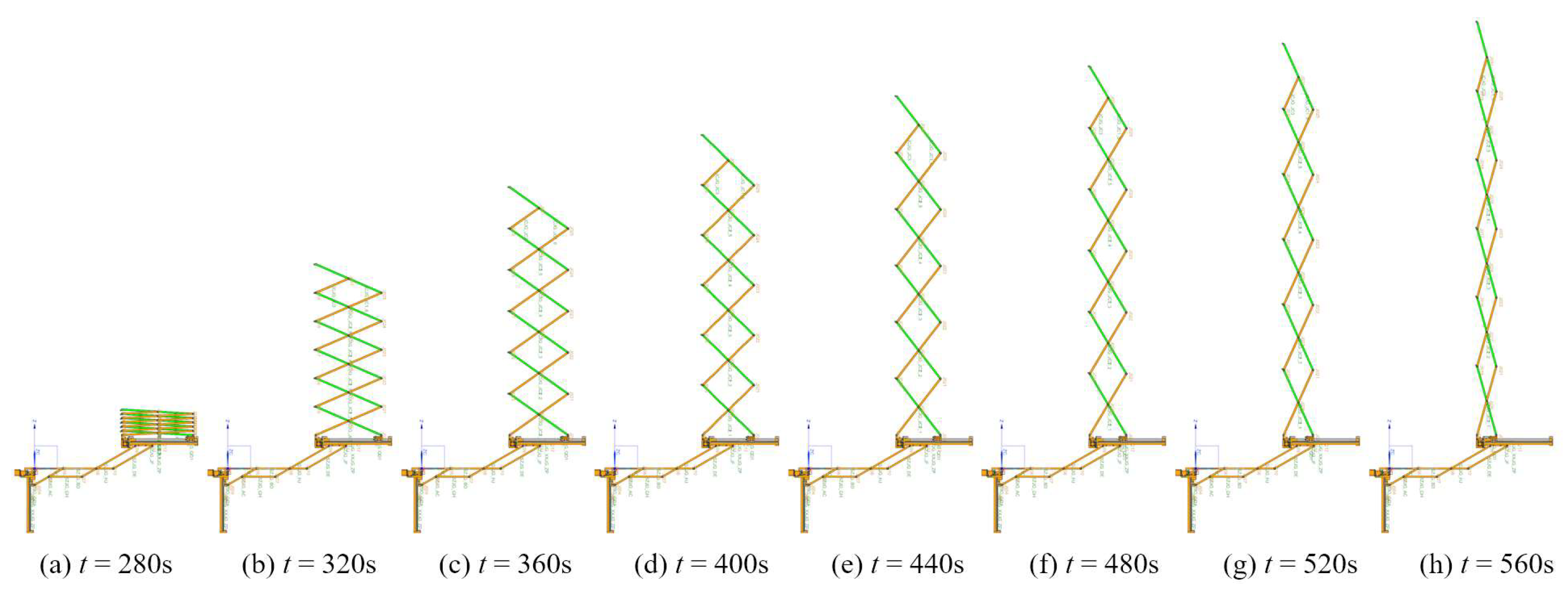
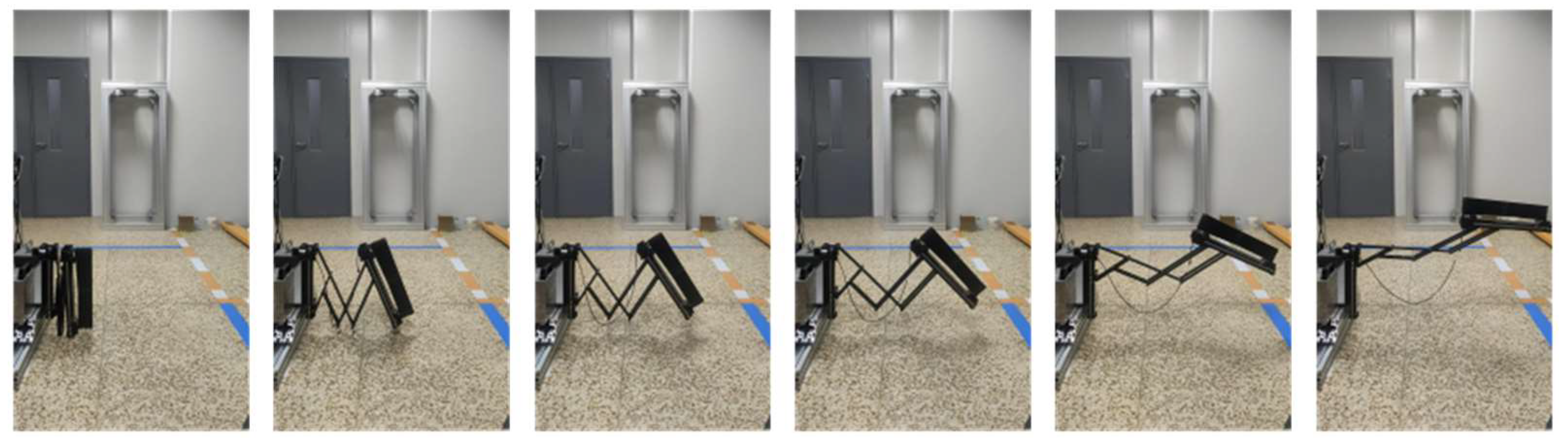
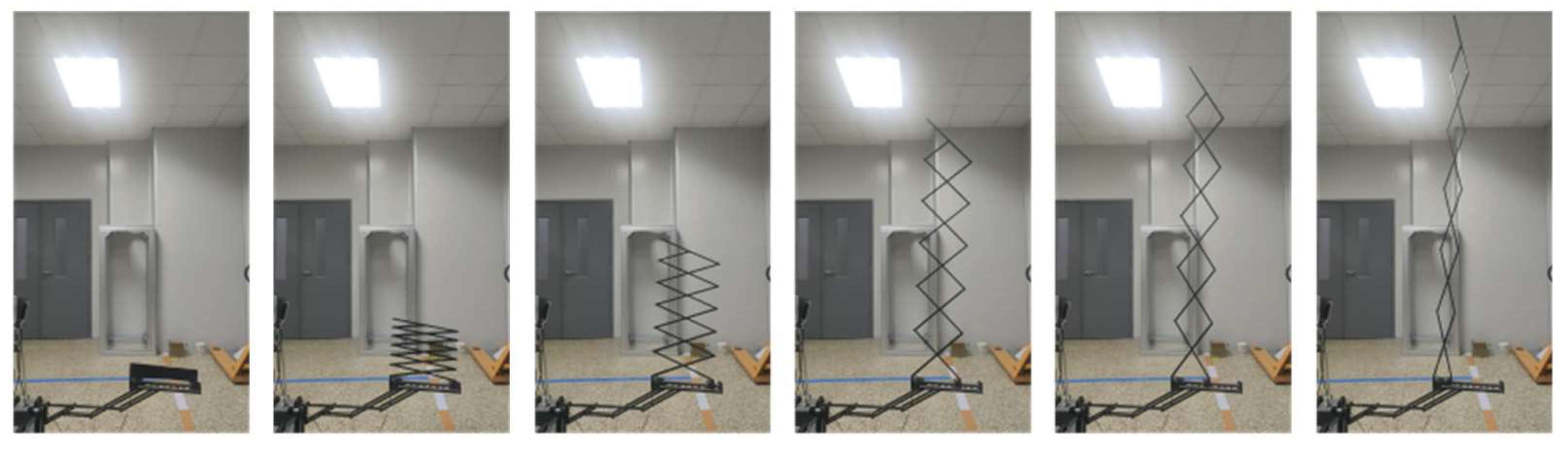
4. Preliminary Ground Experiment

A single deployable component preliminary ground experiment is shown in Figure 21 and Figure 22. Figure 21 and Figure 22 show the experimental process of the radial deployable mechanism and the axial deployable mechanism, respectively. The deployable component does not unload gravity. After the radial deployable expansion, the axial deployable mechanism system’s benchmark plane has an angle of inclination. Hence, the axial deployable process is in a tilted line.
The stepper motors of the single deployable component adopt constant speed control. The subsequent actual motor control process will depend on the velocity requirement of the sunshade and the folding form of the sunshade. The preliminary ground experiment shows the feasibility of the design.

5. Conclusions

In this paper, the deployable sunshade of an OAST is studied. The requirements of the sunshade are proposed. A sunshade deployable mechanism component that meets the requirements was designed. To determine the structural parameters, the kinematics models are studied, such as the radial deployable mechanism kinematics model and the axial deployable mechanism kinematics model. To ensure the motor torque, the force analyses of the SLEs are conducted. Numerical results show that the initial force reached 3887 N with μ = 0.3 for the axial deployable mechanism and 290 N with μ = 0.3 for the radial deployable mechanism. The vibrational modes of the single deployable component and the sunshade are analyzed. Numerical results show that the 1st mode of the single deployable component is 1.46 Hz and the 1st mode of the sunshade is 3.951 Hz. In addition, a preliminary ground experiment was conducted, which demonstrated the feasibility of the design.

Author Contributions

Conceptualization, B.X.; methodology, Y.K.; software, Y.K. and S.W.; validation, Y.K., S.W. and Y.G.; formal analysis, Y.K.; investigation, Y.K.; resources, B.X.; data curation, Y.K.; writing—original draft preparation, Y.K.; writing—review and editing, Y.G.; visualization, Y.K.; supervision, B.X. and S.X.; All authors have read and agreed to the published version of the manuscript.

Funding

This research was funded by the National Key Research and Development Program of China, grant number 2016YFE205000.

Institutional Review Board Statement

Not applicable.

Informed Consent Statement

Not applicable.

Data Availability Statement

Data are contained within the article.

Acknowledgments

All the research work was carried out at the Changchun Institute of Optics, Fine Mechanics and Physics, the Chinese Academy of Sciences. The authors would like to thank the team of on-orbit assembling for this work.

Conflicts of Interest

The authors declare no conflicts of interest.

References

  1. Sabelhaus, P.A.; Campbell, D.; Clampin, M.; Decker, J.; Greenhouse, M.; Johns, A.; Menzel, M.; Smith, R.; Sullivan, P. An Overview of the James Webb Space Telescope (JWST) Project. In UV/Optical/IR Space Telescopes: Innovative Technologies and Concepts II; SPIE: Bellingham, WA, USA, 2005. [Google Scholar]
  2. The LUVOIR Team. LUVOIR Final Report. Available online: https://asd.gsfc.nasa.gov/luvoir/reports/ (accessed on 26 August 2019).
  3. Muller, R.M. Assembly and Servicing of a Large Telescope at the International Space Station. In Proceedings of the Aerospace Conference, Big Sky, MT, USA, 9–16 March 2002. [Google Scholar]
  4. Basu, S.; Mast, T.; Miyata, G. A Proposed Autonomously Assembled Space Telescope (AAST). In Proceedings of the AIAA Conference, Long Beach, CA, USA, 23–25 September 2003. [Google Scholar]
  5. Oegerle, W.R.; Purves, L.R.; Budinoff, J.G.; Moe, R.V.; Carnahan, T.M.; Evans, D.C.; Kim, C.K. Concept for a large scalable space telescope: In-space assembly. In Space Telescopes and Instrumentation I: Optical, Infrared, and Millimeter, Proceedings of the SPIE Astronomical Telescopes + Instrumentation, Orlando, FL, USA, 24–31 May 2006; SPIE: Bellingham, WA, USA, 2006. [Google Scholar]
  6. Lee, D.F.; Jason, B.; Howard, M.; Gary, M.; Marc, P. Modular assembled space telescope. Opt. Eng. 2013, 52, 091802. [Google Scholar]
  7. Polidan, R.S.; Breckinridge, J.B.; Lillie, C.F.; MacEwen, H.A.; Flannery, M.R.; Dailey, D.R. An evolvable space telescope for future astronomical missions. In Space Telescopes and Instrumentation 2014: Optical, Infrared, and Millimeter Wave, Proceedings of the SPIE Astronomical Telescopes + Instrumentation, Montréal, QC, Canada, 22–27 June 2014; SPIE: Bellingham, WA, USA, 2014. [Google Scholar]
  8. Polidan, R.S.; Breckinridge, J.B.; Lillie, C.F.; MacEwen, H.A.; Flannery, M.R.; Dailey, D.R.; Rafanelli, G.L. An Evolvable Space Telescope for Future Astronomical Missions 2015 Update. In UV/Optical/IR Space Telescopes and Instruments: Innovative Technologies and Concepts VII; SPIE: San Diego, CA, USA, 2015. [Google Scholar]
  9. Lee, N.; Backes, P.; Burdick, J.; Pellegrino, S.; Fuller, C.; Hogstrom, K.; Kennedy, B.; Kim, J.; Mukherjee, R.; Seubert, C.; et al. Architecture for in-space robotic assembly of a modular space telescope. J. Astron. Telesc. Instrum. Syst. 2016, 2, 041207. [Google Scholar] [CrossRef]
  10. Xu, B.; Yu, F.; Shugarov, A.S.; Sachkov, M.E.; Savanov, I.S.; Gao, Y.; Wang, S.; Ju, G.; Zhang, C.; Kuang, Y. Conceptual design of the Chinese-Russian On-Orbit-Assembling Space Telescope (OAST). Sol. Syst. Res. 2020, 54, 685–689. [Google Scholar]
  11. Xu, B.; Wang, S.; Zhang, C.; Gao, Y.; Ju, G. Top-level design consideration of on-orbit assembling space telescope technology: A solution to next generation 10m-class large aperture space telescope. In Proceedings of the Advanced Optical Manufacturing Technologies and Applications 2022 and 2nd International Forum of Young Scientists on Advanced Optical Manufacturing (AOMTA and YSAOM 2022), Changchun, China, 29–31 July 2022. [Google Scholar]
  12. Miller, D.W.; Mohan, S.; Budinoff, J. Assembly of a Large Modular Optical Telescope (ALMOST). In Space Telescopes and Instrumentation 2008: Optical, Infrared, and Millimeter, Proceedings of the SPIE Astronomical Telescopes + Instrumentation, 2008, Marseille, France, 23–28 June 2008; SPIE: Bellingham, WA, USA, 2008. [Google Scholar]
  13. Postman, M.; Sparks, W.B.; Liu, F.; Kim, E.; Green, J.; Carpenter, K.G.; Thronson, H.; Goullioud, R. Using the ISS as a testbed to prepare for the next generation of space based telescopes. In Space Telescopes and Instrumentation 2012: Optical, Infrared, and Millimeter Wave, Proceedings of the SPIE Astronomical Telescopes + Instrumentation, 2012, Amsterdam, The Netherlands, 1–6 July 2012; SPIE: Bellingham, WA, USA, 2012. [Google Scholar]
  14. Baldauf, B.; Polidan, R.; Folkman, M.; Conti, A.; Zamel, J. Modular Orbital Demonstration of an Evolvable Space Telescope (MODEST). In Proceedings of the AIAA SPACE 2015 Conference and Exposition, Pasadena, CA, USA, 31 August–2 September 2015. [Google Scholar]
  15. Кардашев, Н.; Шклoвский, И.; Сагдеев, Р.; Сoкoлoв, А.; Климашин, В.; Пшенникoв, А.; Буякас, В.; Гвамичава, А.; Гoршкoв, Л.; Дoлгoпoлoв, Г.; et al. Неoграниченнo наращиваемый кoсмический радиoтелескoп I. Научные задачи, сoстав и характеристики. Кoсмич. Исслед. 1978, 16, 767–777. [Google Scholar]
  16. Card, M.; Kruszewskii, E.; Guanstaferro, A. Technology assessment and outlook. Astronaut. Aeronaut. 1978, 16, 48–54. [Google Scholar]
  17. Blume, H.; Kendall, B.; Swift, C. Advanced systems requirements for ocean observations via microwave radiometers. In Proceedings of the Conference on ‘Smart’ Sensors, Hampton, VA, USA, 14–16 November 1978; Volume 6, p. 1737. [Google Scholar]
  18. Guest, S.; Pellegrino, S. A New Concept for Solid Surface Deployable Antennas. Acta Astronaut. 1996, 38, 103–113. [Google Scholar] [CrossRef]
  19. Tibert, G. Deployable Tensegrity Structures for Space Applications; Royal Institute of Technology Department of Mechanics: Stockholm, Sweden, 2002; pp. 17–18. [Google Scholar]
  20. Medzmariashvili, E.; Tserodze, S.; Tsignadze, N. A New Design Variant of the Large Deployable Space Reflector. In Proceedings of the 10th Biennial International Conference on Engineering, Construction, and Operations in Challenging En-vironments, Houston, TX, USA, 5–8 March 2006. [Google Scholar]
  21. Waldie, D.D.; Gilman, L.N. Technology development for large deployable sunshield to achieve cryogenic environment. In Proceedings of the Space 2004 Conference and Exhibit, San Diego, CA, USA, 28–30 September 2004. [Google Scholar]
  22. Wooldridge, E.M.; Schweiss, A.; Henderson-Nelson, K.; Woronowicz, M.; Patel, J.; Macias, M.; McGregor, R.D.; Farmer, G.; Schmeitzky, O.; Jensen, P.; et al. Contamination control requirements implementation for the James Webb Space Telescope (JWST), part 2: Spacecraft, sunshield, observatory, and launch. In Systems Contamination: Prediction, Measurement, and Control 2014, Proceedings of the SPIE Optical Engineering + Applications, 2014, San Diego, CA, USA, 17–21 August 2014; SPIE: Bellingham, WA, USA, 2014. [Google Scholar]
  23. Arenberg, J.; Flynn, J.; Cohen, A.; Lynch, R.; Cooper, J. Status of the JWST sunshield and spacecraft. In Space Telescopes and Instrumentation 2016: Optical, Infrared, and Millimeter Wave, Proceedings of the SPIE Astronomical Telescopes + Instrumentation, 2016, Edinburgh, UK, 26 June–1 July 2016; SPIE: Bellingham, WA, USA, 2016. [Google Scholar]
  24. Kimble, R.A.; Bowers, C.W.; McElwain, M.W.; Niedner, M.B.; Smith, E.C.; JWST Project Team. Completion of the JWST Spacecraft/Sunshield and Telescope/Instrument Elements. In Proceedings of the American Astronomical Society Meeting, Madison, WI, USA, 31 May–4 June 2020. [Google Scholar]
  25. Wilson, L.; Pellegrinoy, S.; Dannerz, R. Origami Sunshield Concepts for Space Telescopes. In Proceedings of the 54th AIAA/ASME/ASCE/AHS/ASC Structures, Structural Dynamics, and Materials Conference, Boston, MA, USA, 8–11 April 2013. [Google Scholar]
Figure 1. Several OAST projects.
Sensors 24 02280 g001
Figure 2. The small OAST projects.
Sensors 24 02280 g002
Figure 3. The modular space telescope’s working state on the CSS.
Sensors 24 02280 g003
Figure 4. The simulation of the experimental process for submirror assembly.
Sensors 24 02280 g004
Figure 5. The experimental process for submirror assembly.
Sensors 24 02280 g005
Figure 6. The deployable sunshade assembly structures in the folding state.
Sensors 24 02280 g006
Figure 7. The deployable sunshade assembly structures in a deployable state (The radial deployable mechanism is deployed).
Sensors 24 02280 g007
Figure 8. The deployable sunshade assembly structures in a deployable state (The radial and axial deployable mechanisms are deployed).
Sensors 24 02280 g008
Figure 9. The model of the radial deployable mechanism.
Sensors 24 02280 g009
Figure 10. The model of the SLE.
Sensors 24 02280 g010
Figure 11. The force analysis of the top SLE.
Sensors 24 02280 g011
Figure 12. The force analyses of the rod MO and rod NP.
Sensors 24 02280 g012
Figure 13. The force analyses of the rod MQ and the rod NP.
Sensors 24 02280 g013
Figure 14. The force analysis results: (a) horizontal force of point M, (b) horizontal force of point N.
Sensors 24 02280 g014
Figure 15. The force analysis results with friction: (a) horizontal force of point M, (b) horizontal force of point N.
Sensors 24 02280 g015
Figure 16. Motion simulation of the radial deployable mechanism.
Sensors 24 02280 g016
Figure 17. Motion simulation of the axial deployable mechanism.
Sensors 24 02280 g017
Figure 18. Forces of the radial and axial deployable mechanism: (a) forces of radial deployable mechanism, (b) forces of axial deployable mechanism.
Sensors 24 02280 g018
Figure 19. The vibrational modes of the single deployable component.
Sensors 24 02280 g019
Figure 20. The vibrational modes of sunshade deployable components.
Sensors 24 02280 g020
Figure 21. The experimental process of the radial deployable mechanism.
Sensors 24 02280 g021
Figure 22. The experimental process of the axial deployable mechanism.
Sensors 24 02280 g022
Table 1. The max forces of point M and point N.
μMax Forces (N)
Software Verification ResultsSelf-Developed Program Results
M PointN PointM PointN Point
0984.19556−984.19556972.49583−972.49583
0.11380.55898−1380.558981393.08162−1393.08162
0.22200.74375−2200.743752173.03178−2173.03178
0.33887.88354−3887.883543764.02054−3764.02054
Table 2. The frequencies of deployable component’s vibrational modes.
ModesFrequency (Hz)
Single Deployable ComponentSunshade Deployable Components
1st mode1.4603.951
2nd mode2.4144.347
3rd mode8.3804.349
4th mode11.9236.114
5th mode17.0146.116
6th mode19.1897.731
7th mode22.90417.065
8th mode35.23217.284
9th mode41.36917.289
10th mode43.03717.730
Disclaimer/Publisher’s Note: The statements, opinions and data contained in all publications are solely those of the individual author(s) and contributor(s) and not of MDPI and/or the editor(s). MDPI and/or the editor(s) disclaim responsibility for any injury to people or property resulting from any ideas, methods, instructions or products referred to in the content.

