
Testing and Analysis of Selected Navigation Parameters of the GNSS/INS System for USV Path Localization during Inland Hydrographic Surveys

Abstract
:1. Introduction
2. Materials and Methods
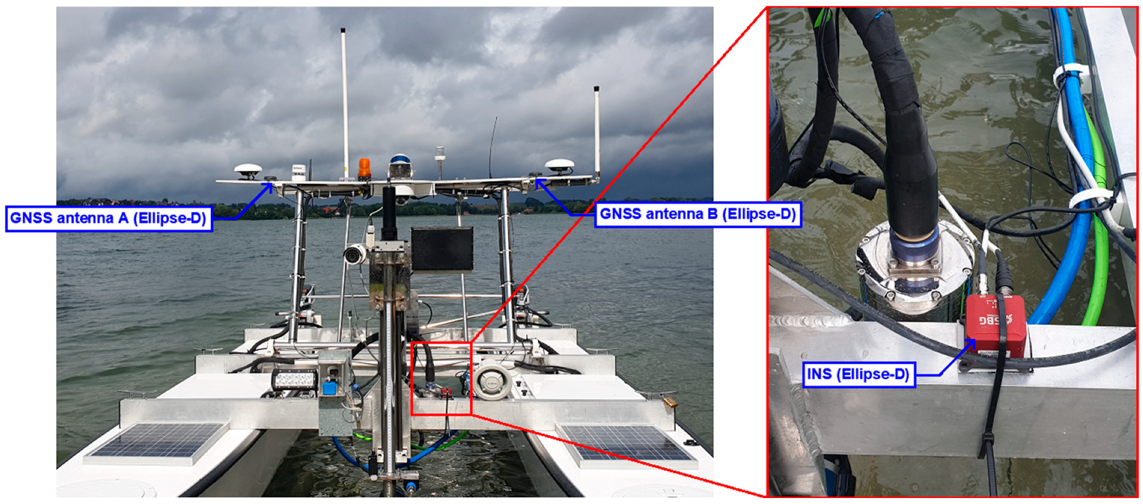
2.1. Measurement Equipment
- IMU is the main component of an INS. It comprises three gyroscopes, three accelerometers and three magnetometers, which are applied to determine angular velocities and accelerations along the RPY axis: roll, pitch and yaw of the moving vehicle. Detailed technical data of measurement devices included in the Ellipse-D IMU are presented in [52];
- Two GNSS antennas are applied to determine the course of a moving object. They receive satellite signals from GPS: L1 C/A and L2C; GLObal Navigation Satellite System (GLONASS): L1OF and L2OF; BeiDou Navigation Satellite System (BDS): B1 and B2; as well as Galileo: E1 and E5b. The update rate of GNSS signals is 5 Hz;
- sbgCenter software is applied to configure and control GNSS/INS measurement parameters in real time.
- The GNSS/INS system allows operation in two modes:
- ○
- Differential—a method that transmits differential observations via a General Packet Radio Service (GPRS)/Wireless Local Area Network (WLAN), a satellite connection or Very High Frequency (VHF) from a base station (the so-called reference station) with known coordinates to a mobile receiver for which the position coordinates are determined. This measurement technique enables a positioning accuracy of up to tens of centimetres.
- ○
- RTK—a method that transmits L1 and L2 carrier phase observations from a base station with known coordinates to a mobile receiver for which the position coordinates are determined. The positioning accuracy at the centimetre level is provided by double-difference measurements and the integer ambiguity resolution.
- GNSS/INS data: accelerations, angles and position coordinates should be recorded as frequently as possible. The Ellipse-D system allows measurements to be registered with the frequency of 200 Hz.
- Adaptive—designed to move longer distances without operator intervention. After setting the course, the vessel will move it regardless of weather conditions, making corrections on an ongoing basis to maintain the set direction;
- Autonomous—the basic setting allowing autonomous measurements. It enables the setting of route points along which the vessel will move, while simultaneously conducting data acquisition;
- Dynamic positioning—a useful mode when it is necessary to maintain a constant position, e.g., when determining the speed of sound in water in a vertical profile. The vessel will compensate for the impact of wind and other forces acting on it to stop drifting and stay in one place as much as possible;
- Manual—a mode enabling manual control by the operator, e.g., when mooring the vessel or to reach the measurement area with the anti-collision module still active, which will prevent a collision with another watercraft. Additionally, the position, course and all important navigational information are constantly displayed on the chart.
2.2. GNSS/INS Measurements
2.3. GNSS/INS Data Processing
- λ—failure rate,
- μ—renewal rate.
3. Results
4. Discussion
5. Conclusions
Funding
Informed Consent Statement
Data Availability Statement
Conflicts of Interest
References
- Barrera, C.; Padrón Armas, I.; Luis, F.; Llinas, O.; Marichal, N. Trends and Challenges in Unmanned Surface Vehicles (USV): From Survey to Shipping. TransNav Int. J. Mar. Navig. Saf. Sea Transp. 2021, 15, 135–142. [Google Scholar] [CrossRef]
- Liu, Z.; Zhang, Y.; Yu, X.; Yuan, C. Unmanned Surface Vehicles: An Overview of Developments and Challenges. Annu. Rev. Control 2016, 41, 71–93. [Google Scholar] [CrossRef]
- Makar, A. Determination of USV’s Direction Using Satellite and Fluxgate Compasses and GNSS-RTK. Sensors 2022, 22, 7895. [Google Scholar] [CrossRef] [PubMed]
- Włodarczyk-Sielicka, M.; Połap, D.; Prokop, K.; Połap, K.; Stateczny, A. Spatial Visualization Based on Geodata Fusion Using an Autonomous Unmanned Vessel. Remote Sens. 2023, 15, 1763. [Google Scholar] [CrossRef]
- Breivik, M.; Hovstein, V.E.; Fossen, T.I. Straight-line Target Tracking for Unmanned Surface Vehicles. Model. Identif. Control 2008, 29, 131–149. [Google Scholar] [CrossRef]
- Makar, A. Coastal Bathymetric Sounding in Very Shallow Water Using USV: Study of Public Beach in Gdynia, Poland. Sensors 2023, 23, 4215. [Google Scholar] [CrossRef]
- Sun, X.; Wang, G.; Fan, Y.; Mu, D.; Qiu, B. An Automatic Navigation System for Unmanned Surface Vehicles in Realistic Sea Environments. Appl. Sci. 2018, 8, 193. [Google Scholar] [CrossRef]
- Burdziakowski, P.; Stateczny, A. Universal Autonomous Control and Management System for Multipurpose Unmanned Surface Vessel. Pol. Mar. Res. 2019, 26, 30–39. [Google Scholar]
- Lewicka, O. Method for Accuracy Assessment of Topo-bathymetric Surface Models Based on Geospatial Data Recorded by UAV and USV Vehicles. Metrol. Meas. Syst. 2023, 30, 461–480. [Google Scholar] [CrossRef]
- Mujta, W.; Wlodarczyk-Sielicka, M.; Stateczny, A. Testing the Effect of Bathymetric Data Reduction on the Shape of the Digital Bottom Model. Sensors 2023, 23, 5445. [Google Scholar] [CrossRef]
- Shen, W.; Yang, Z.; Yang, C.; Li, X. A LiDAR SLAM-assisted Fusion Positioning Method for USVs. Sensors 2023, 23, 1558. [Google Scholar] [CrossRef]
- Stateczny, A.; Kazimierski, W.; Gronska-Sledz, D.; Motyl, W. The Empirical Application of Automotive 3D Radar Sensor for Target Detection for an Autonomous Surface Vehicle’s Navigation. Remote Sens. 2019, 11, 1156. [Google Scholar] [CrossRef]
- Pu, H.; Liu, Y.; Luo, J.; Xie, S.; Peng, Y.; Yang, Y.; Yang, Y.; Li, X.; Su, Z.; Gao, S.; et al. Development of an Unmanned Surface Vehicle for the Emergency Response Mission of the ‘Sanchi’ Oil Tanker Collision and Explosion Accident. Appl. Sci. 2020, 10, 2704. [Google Scholar] [CrossRef]
- Solana Rubio, S.; Salas Romero, A.; Cerezo Andreo, F.; González Gallero, R.; Rengel, J.; Rioja, L.; Callejo, J.; Bethencourt, M. Comparison between the Employment of a Multibeam Echosounder on an Unmanned Surface Vehicle and Traditional Photogrammetry as Techniques for Documentation and Monitoring of Shallow-water Cultural Heritage Sites: A Case Study in the Bay of Algeciras. J. Mar. Sci. Eng. 2023, 11, 1339. [Google Scholar] [CrossRef]
- Totland, A.; Johnsen, E. Kayak Drone—A Silent Acoustic Unmanned Surface Vehicle for Marine Research. Front. Mar. Sci. 2022, 9, 986752. [Google Scholar] [CrossRef]
- Specht, M.; Specht, C.; Stateczny, A.; Marchel, Ł.; Lewicka, O.; Paliszewska-Mojsiuk, M.; Wiśniewska, M. Determining the Seasonal Variability of the Territorial Sea Baseline in Poland (2018–2020) Using Integrated USV/GNSS/SBES Measurements. Energies 2021, 14, 2693. [Google Scholar] [CrossRef]
- Specht, M.; Stateczny, A.; Specht, C.; Widźgowski, S.; Lewicka, O.; Wiśniewska, M. Concept of an Innovative Autonomous Unmanned System for Bathymetric Monitoring of Shallow Waterbodies (INNOBAT System). Energies 2021, 14, 5370. [Google Scholar] [CrossRef]
- Chang, H.-C.; Hsu, Y.-L.; Hung, S.-S.; Ou, G.-R.; Wu, J.-R.; Hsu, C. Autonomous Water Quality Monitoring and Water Surface Cleaning for Unmanned Surface Vehicle. Sensors 2021, 21, 1102. [Google Scholar] [CrossRef] [PubMed]
- Ferri, G.; Manzi, A.; Fornai, F.; Ciuchi, F.; Laschi, C. The HydroNet ASV, a Small-sized Autonomous Catamaran for Real-time Monitoring of Water Quality: From Design to Missions at Sea. IEEE J. Ocean. Eng. 2015, 40, 710–726. [Google Scholar] [CrossRef]
- Chen, H.; Zhu, C.; Chen, J.; Peng, Y.; Yao, J. Design of Unmanned Surface Vehicle for Submarine Pipeline Detection. In Proceedings of the 2018 IEEE 4th Information Technology and Mechatronics Engineering Conference (ITOEC 2018), Chongqing, China, 14–16 December 2018. [Google Scholar]
- Nikolakopoulos, K.G.; Lampropoulou, P.; Fakiris, E.; Sardelianos, D.; Papatheodorou, G. Synergistic Use of UAV and USV Data and Petrographic Analyses for the Investigation of Beachrock Formations: A Case Study from Syros Island, Aegean Sea, Greece. Minerals 2018, 8, 534. [Google Scholar] [CrossRef]
- Wang, Y.; Liu, W.; Liu, J.; Sun, C. Cooperative USV–UAV Marine Search and Rescue with Visual Navigation and Reinforcement Learning-based Control. ISA Trans. 2023, 137, 222–235. [Google Scholar] [CrossRef] [PubMed]
- Xiao, X.; Dufek, J.; Woodbury, T.; Murphy, R. UAV Assisted USV Visual Navigation for Marine Mass Casualty Incident Response. In Proceedings of the 2017 IEEE/RSJ International Conference on Intelligent Robots and Systems (IROS 2017), Vancouver, BC, Canada, 24–28 September 2017. [Google Scholar]
- Patterson, R.G.; Lawson, E.; Udyawer, V.; Brassington, G.B.; Groom, R.A.; Campbell, H.A. Uncrewed Surface Vessel Technological Diffusion Depends on Cross-sectoral Investment in Open-ocean Archetypes: A Systematic Review of USV Applications and Drivers. Front. Mar. Sci. 2021, 8, 736984. [Google Scholar] [CrossRef]
- Xie, J.; Zhou, R.; Luo, J.; Peng, Y.; Liu, Y.; Xie, S.; Pu, H. Hybrid Partition-based Patrolling Scheme for Maritime Area Patrol with Multiple Cooperative Unmanned Surface Vehicles. J. Mar. Sci. Eng. 2020, 8, 936. [Google Scholar] [CrossRef]
- Marchel, Ł.; Specht, C.; Specht, M. Assessment of the Steering Precision of a Hydrographic USV along Sounding Profiles Using a High-precision GNSS RTK Receiver Supported Autopilot. Energies 2020, 13, 5637. [Google Scholar] [CrossRef]
- Makar, A. Determination of the Minimum Safe Distance between a USV and a Hydro-engineering Structure in a Restricted Water Region Sounding. Energies 2022, 15, 2441. [Google Scholar] [CrossRef]
- Makar, A. Limitations of Multi-GNSS Positioning of USV in Area with High Harbour Infrastructure. Electronics 2023, 12, 697. [Google Scholar] [CrossRef]
- Stateczny, A.; Burdziakowski, P.; Najdecka, K.; Domagalska-Stateczna, B. Accuracy of Trajectory Tracking Based on Nonlinear Guidance Logic for Hydrographic Unmanned Surface Vessels. Sensors 2020, 20, 832. [Google Scholar] [CrossRef] [PubMed]
- Won, D.H.; Lee, E.; Heo, M.; Lee, S.-W.; Lee, J.; Kim, J.; Sung, S.; Jae, Y. Selective Integration of GNSS, Vision Sensor, and INS Using Weighted DOP Under GNSS-challenged Environments. IEEE Trans. Instrum. Meas. 2014, 63, 2288–2298. [Google Scholar] [CrossRef]
- Yan, P.; Jiang, J.; Tang, Y.; Zhang, F.; Xie, D.; Wu, J.; Liu, J.; Liu, J. Dynamic Adaptive Low Power Adjustment Scheme for Single-frequency GNSS/MEMS-IMU/Odometer Integrated Navigation in the Complex Urban Environment. Remote Sens. 2021, 13, 3236. [Google Scholar] [CrossRef]
- Vagle, N.; Broumandan, A.; Lachapelle, G. Multi-antenna GNSS and Inertial Sensors/Odometer Coupling for Robust Vehicular Navigation. IEEE Internet Things J. 2018, 5, 4816–4828. [Google Scholar] [CrossRef]
- Yang, L.; Li, Y.; Wu, Y.; Rizos, C. An Enhanced MEMS-INS/GNSS Integrated System with Fault Detection and Exclusion Capability for Land Vehicle Navigation in Urban Areas. GPS Solut. 2014, 18, 593–603. [Google Scholar] [CrossRef]
- Yan, W.; Zhang, Q.; Zhang, Y.; Wang, A.; Zhao, C. The Validation and Performance Assessment of the Android Smartphone Based GNSS/INS Coupled Navigation System. In Proceedings of the 12th China Satellite Navigation Conference (CSNC 2021), Nanchang, China, 22–25 May 2021. [Google Scholar]
- Gang, H.-S.; Pyun, J.-Y. A Smartphone Indoor Positioning System Using Hybrid Localization Technology. Energies 2019, 12, 3702. [Google Scholar] [CrossRef]
- Jing, S.; Zhan, X.; Liu, B.; Chen, M. Weak and Dynamic GNSS Signal Tracking Strategies for Flight Missions in the Space Service Volume. Sensors 2016, 16, 1412. [Google Scholar] [CrossRef] [PubMed]
- Li, N.; Guan, L.; Gao, Y.; Du, S.; Wu, M.; Guang, X.; Cong, X. Indoor and Outdoor Low-cost Seamless Integrated Navigation System Based on the Integration of INS/GNSS/LIDAR System. Remote Sens. 2020, 12, 3271. [Google Scholar] [CrossRef]
- Zhuang, Y.; Lan, H.; Li, Y.; El-Sheimy, N. PDR/INS/WiFi Integration Based on Handheld Devices for Indoor Pedestrian Navigation. Micromachines 2015, 6, 793–812. [Google Scholar] [CrossRef]
- Pytka, J.; Budzyński, P.; Józwik, J.; Michałowska, J.; Tofil, A.; Łyszczyk, T.; Błażejczak, D. Application of GNSS/INS and an Optical Sensor for Determining Airplane Takeoff and Landing Performance on a Grassy Airfield. Sensors 2019, 19, 5492. [Google Scholar] [CrossRef] [PubMed]
- Qian, C.; Liu, H.; Tang, J.; Chen, Y.; Kaartinen, H.; Kukko, A.; Zhu, L.; Liang, X.; Chen, L.; Hyyppä, J. An Integrated GNSS/INS/LiDAR-SLAM Positioning Method for Highly Accurate Forest Stem Mapping. Remote Sens. 2017, 9, 3. [Google Scholar] [CrossRef]
- El-Diasty, M. Development of Real-time PPP-based GPS/INS Integration System Using IGS Real-time Service for Hydrographic Surveys. J. Surv. Eng. 2016, 142, 05015005. [Google Scholar] [CrossRef]
- El-Diasty, M. Evaluation of KSACORS-based Network GNSS-INS Integrated System for Saudi Coastal Hydrographic Surveys. Geomat. Nat. Hazards Risk 2020, 11, 1426–1446. [Google Scholar] [CrossRef]
- Elsheikh, M.; Abdelfatah, W.; Noureldin, A.; Iqbal, U.; Korenberg, M. Low-cost Real-time PPP/INS Integration for Automated Land Vehicles. Sensors 2019, 19, 4896. [Google Scholar] [CrossRef]
- Zhu, F.; Shen, Y.; Wang, Y.; Jia, J.; Zhang, X. Fusing GNSS/INS/Vision with a Priori Feature Map for High-precision and Continuous Navigation. IEEE Sens. J. 2021, 21, 23370–23381. [Google Scholar] [CrossRef]
- Du, S.; Zhang, S.; Gan, X. A Hybrid Fusion Strategy for the Land Vehicle Navigation Using MEMS INS, Odometer and GNSS. IEEE Access 2020, 8, 152512–152522. [Google Scholar] [CrossRef]
- Specht, M.; Specht, C.; Dąbrowski, P.; Czaplewski, K.; Smolarek, L.; Lewicka, O. Road Tests of the Positioning Accuracy of INS/GNSS Systems Based on MEMS Technology for Navigating Railway Vehicles. Energies 2020, 13, 4463. [Google Scholar] [CrossRef]
- Specht, M.; Specht, C.; Stateczny, A.; Burdziakowski, P.; Dąbrowski, P.; Lewicka, O. Study on the Positioning Accuracy of the GNSS/INS System Supported by the RTK Receiver for Railway Measurements. Energies 2022, 15, 4094. [Google Scholar] [CrossRef]
- Sun, Z.; Tang, K.; Wang, X.; Wu, M.; Guo, Y. High-speed Train Tunnel Navigation Method Based on Integrated MIMU/ODO/MC Navigation. Appl. Sci. 2021, 11, 3680. [Google Scholar] [CrossRef]
- Cahyadi, M.; Asfihani, T.; Mardiyanto, R.; Erfianti, R. Loosely Coupled GNSS and IMU Integration for Accurate i-Boat Horizontal Navigation. Int. J. Geoinform. 2022, 18, 111–122. [Google Scholar]
- Choi, W.; Kang, H.; Lee, J. Robust Localization of Unmanned Surface Vehicle Using DDQN-AM. Int. J. Control Autom. Syst. 2021, 19, 1920–1930. [Google Scholar] [CrossRef]
- Liu, W.; Liu, Y.; Bucknall, R. A Robust Localization Method for Unmanned Surface Vehicle (USV) Navigation Using Fuzzy Adaptive Kalman Filtering. IEEE Access 2019, 7, 46071–46083. [Google Scholar] [CrossRef]
- SBG Systems. Ellipse Series. Available online: https://www.sbg-systems.com/products/ellipse-series/ (accessed on 9 April 2024).
- SBG Systems. Ellipse Documentation. Available online: https://support.sbg-systems.com/sc/el/latest/documentations-resources/ellipse-documentation (accessed on 9 April 2024).
- Stateczny, A.; Specht, C.; Specht, M.; Brčić, D.; Jugović, A.; Widźgowski, S.; Wiśniewska, M.; Lewicka, O. Study on the Positioning Accuracy of GNSS/INS Systems Supported by DGPS and RTK Receivers for Hydrographic Surveys. Energies 2021, 14, 7413. [Google Scholar] [CrossRef]
- IHO-S-44; IHO Standards for Hydrographic Surveys, 6.1.0 ed. IHO: Monaco, Monaco, 2022.
- Bouwmeester, E.C.; Heemink, A.W. Optimal Line Spacing in Hydrographic Survey. Int. Hydrogr. Rev. 1993, 70, 37–48. [Google Scholar]
- Specht, O. Land and Seabed Surface Modelling in the Coastal Zone Using UAV/USV-based Data Integration. Sensors 2023, 23, 8020. [Google Scholar] [CrossRef] [PubMed]
- Stenborg, E. The Swedish Parallel Sounding Method State of the Art. Int. Hydrogr. Rev. 1987, 64, 7–14. [Google Scholar]
- Specht, M. Method of Evaluating the Positioning System Capability for Complying with the Minimum Accuracy Requirements for the International Hydrographic Organization Orders. Sensors 2019, 19, 3860. [Google Scholar] [CrossRef] [PubMed]
- Specht, C. Availability, Reliability and Continuity Model of Differential GPS Transmission. Annu. Navig. 2003, 5, 1–85. [Google Scholar]
- Oguntuase, J.O.; Hiroji, A.; Komolafe, P. How Good Is a Tactical-grade GNSS + INS (MEMS and FOG) in a 20-m Bathymetric Survey? Sensors 2023, 23, 754. [Google Scholar] [CrossRef]


| RMSE | Time That Has Elapsed Since the GNSS Signal Was Not Available | |||
|---|---|---|---|---|
| 0 s | 10 s | |||
| DGPS | RTK | DGPS | RTK | |
| 2D position (m) | 1.2 | 0.01 | 3 | 1 |
| Height (m) | 1.5 | 0.02 | 3.5 | 1 |
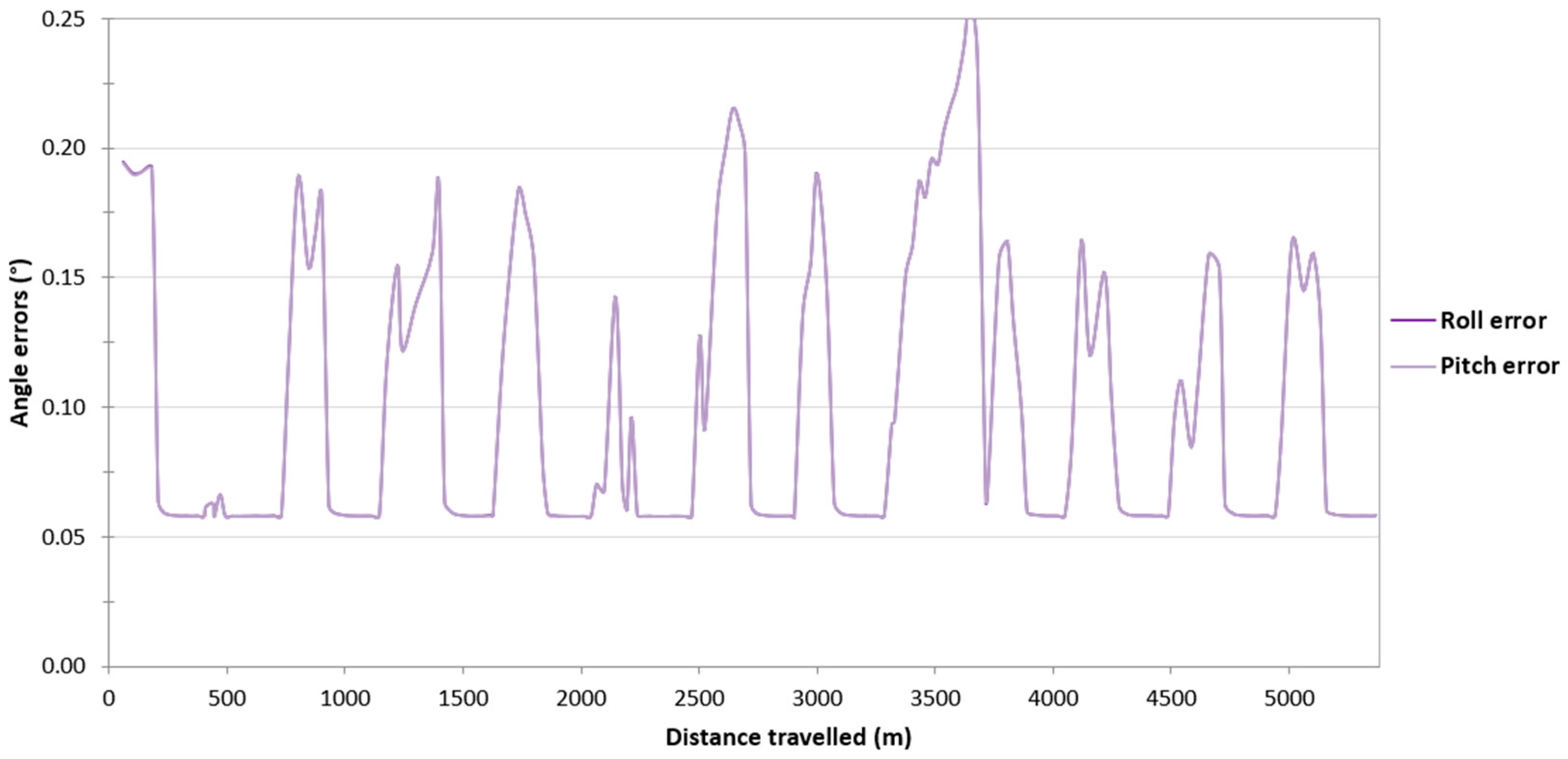
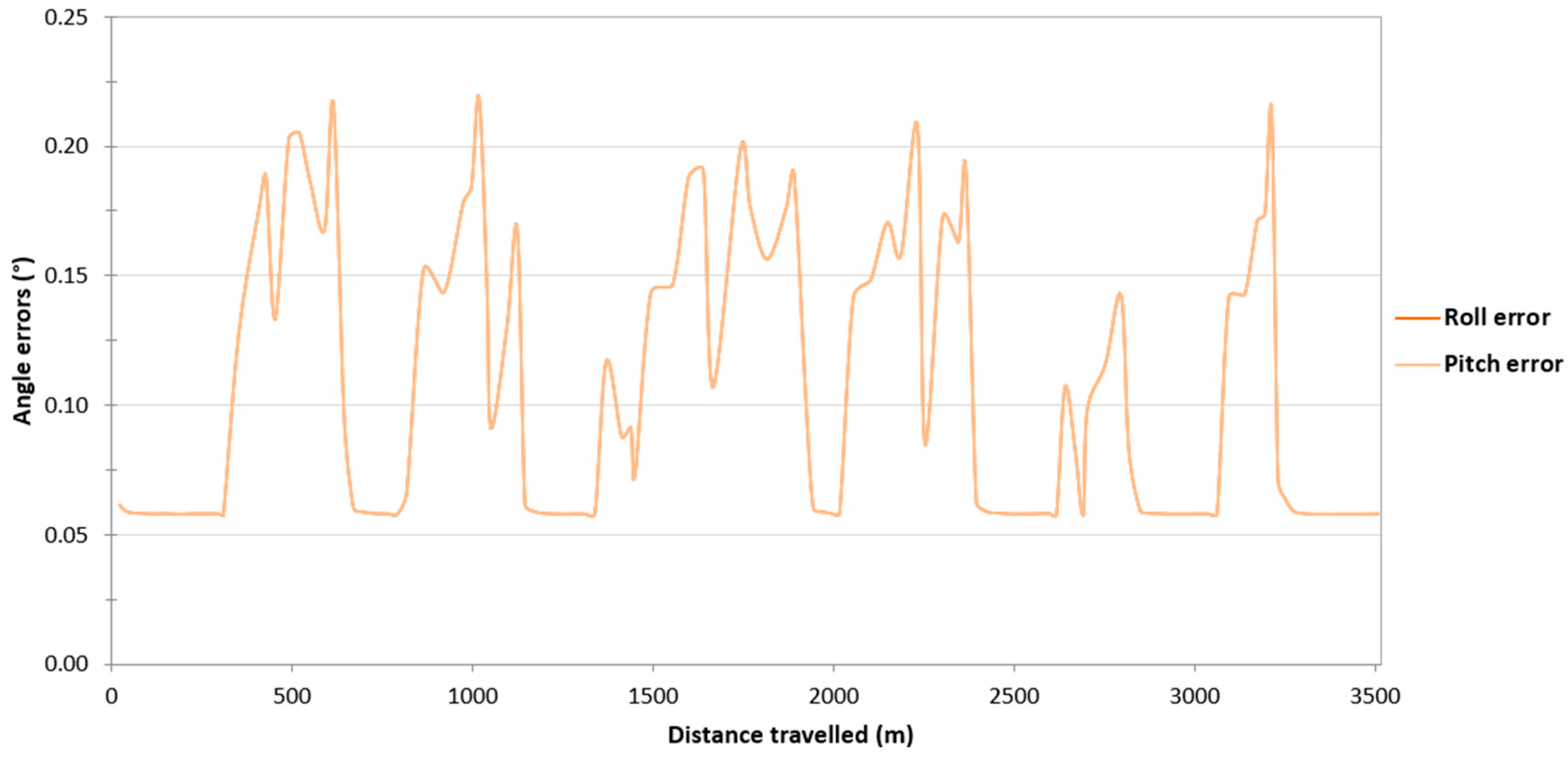
| Pitch, roll (°) | 0.1 | 0.05 | 0.1 | 0.05 |
| Course (°) | 0.8 | 0.2 | 0.8 | 0.2 |
| Position Accuracy Measure | Dimension | Probability | Definition |
|---|---|---|---|
| RMS | 1D | 68.3% | The standard deviation of the position coordinate relative to the latitude (φ), longitude (λ) or height (h). |
| DRMS | 2D | 63.2–68.3% | The square root calculated from the sum of squared standard deviations of position coordinates relative to φ, λ, (h). |
| 3D | |||
| 2DRMS | 2D | 95.4–98.2% | Twice the DRMS. |
| 3D | |||
| CEP | 2D | 50% | The radius of the circle centred at the true position, containing the position estimate with a confidence level of 50%. |
| SEP | 3D | 50% | The radius of the sphere centred at the true position, containing the position estimate with a confidence level of 50%. |
| R68 | 2D | 68% | The radius of the circle (sphere) centred at the true position, containing the position estimate with a confidence level of 68%. |
| 3D | |||
| R95 | 2D | 95% | The radius of the circle (sphere) centred at the true position, containing the position estimate with a confidence level of 95%. |
| 3D |
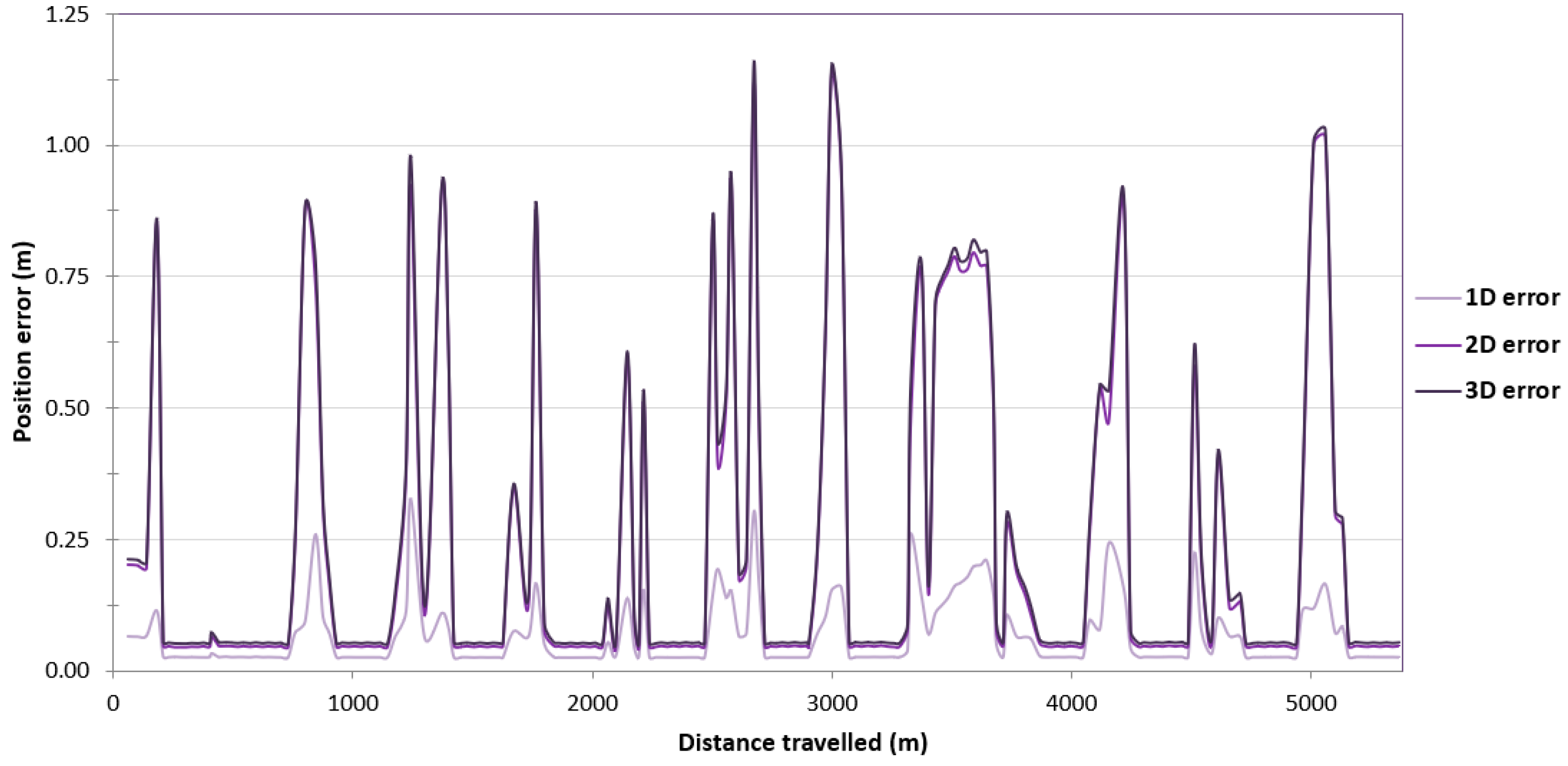
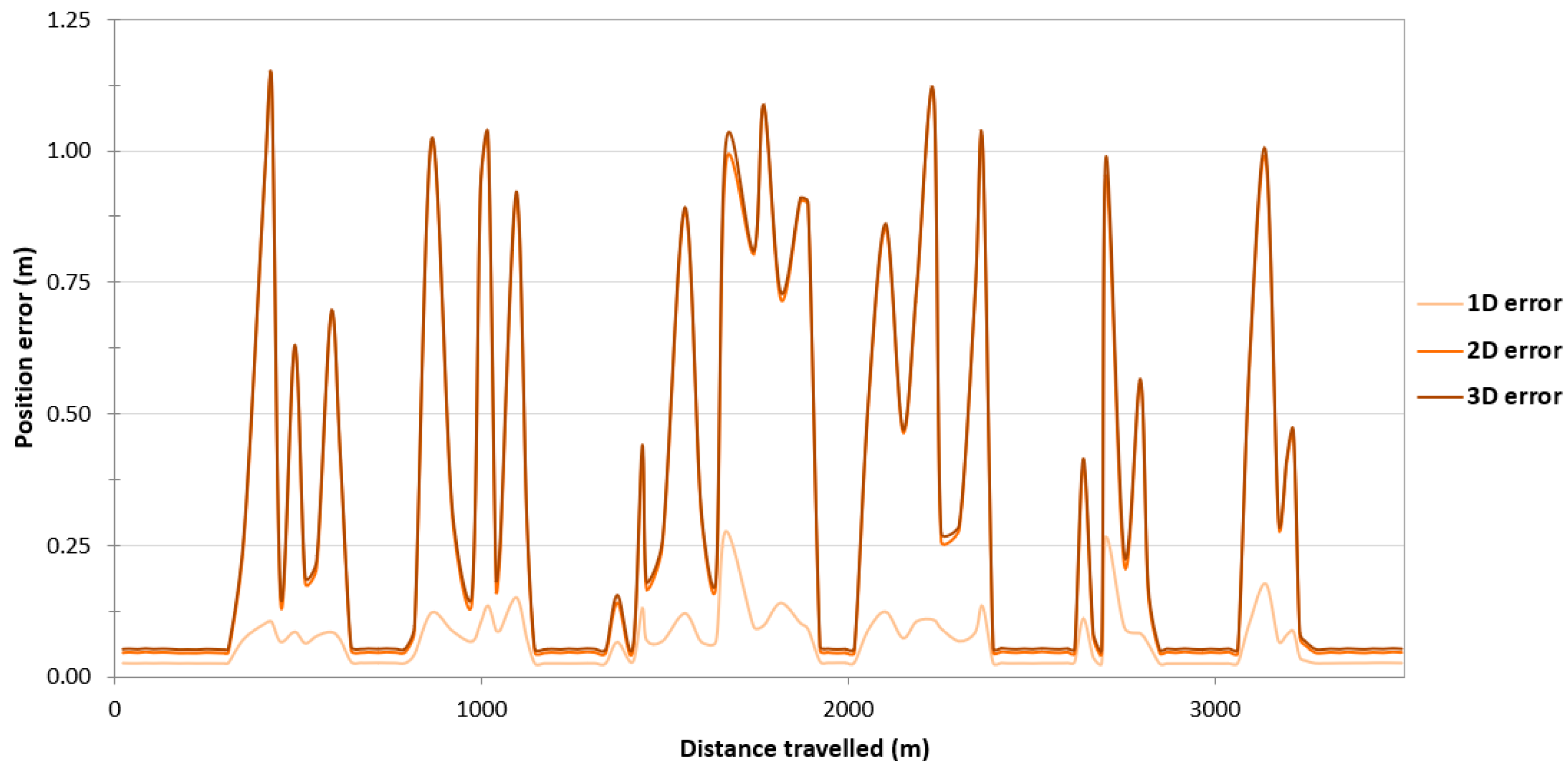
| Statistics of the Position Error | Route No. 1 | Route No. 2 | Route No. 3 | Route No. 4 |
|---|---|---|---|---|
| Number of measurements | 4231 | 2239 | 3729 | 2466 |
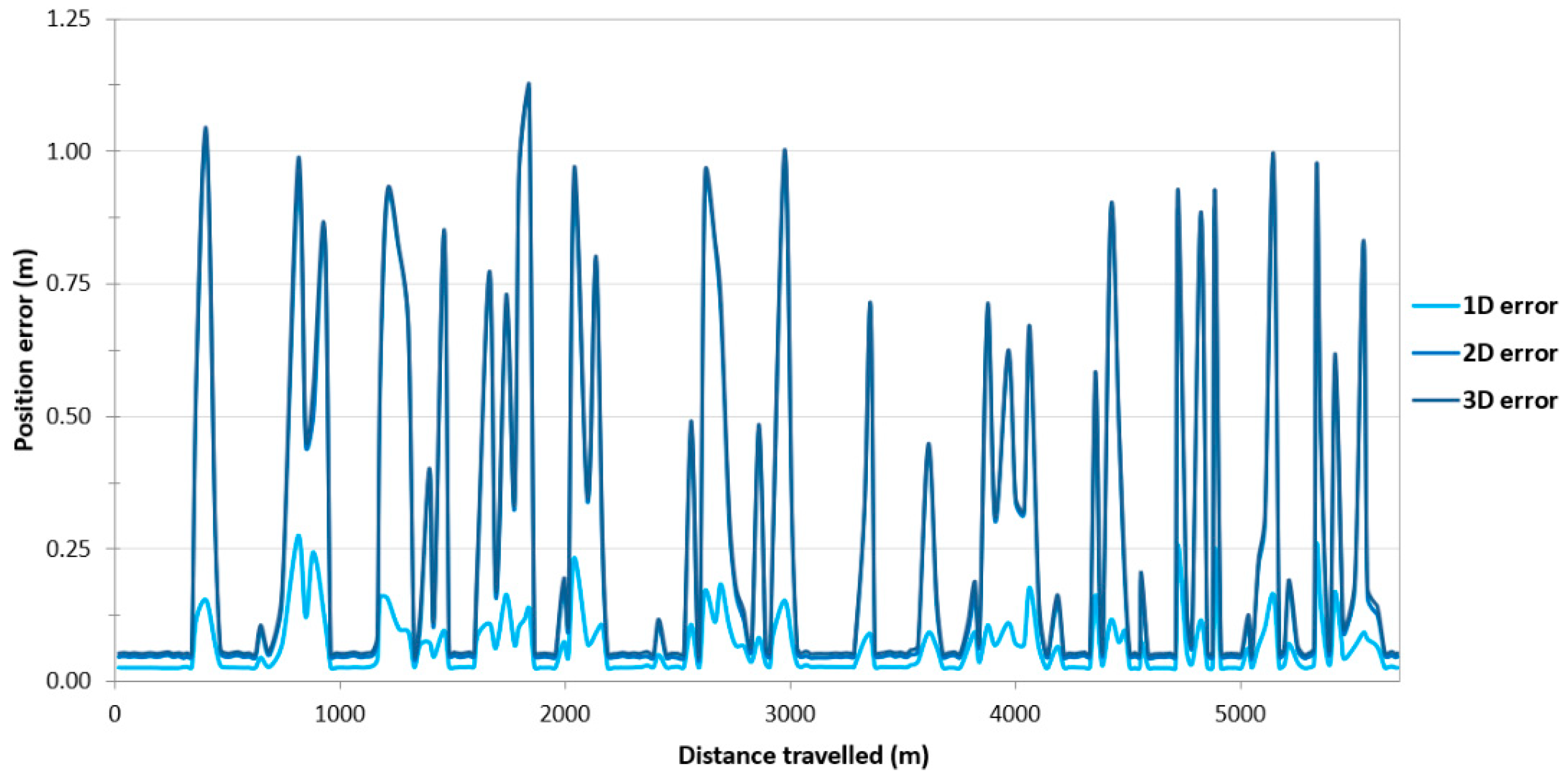
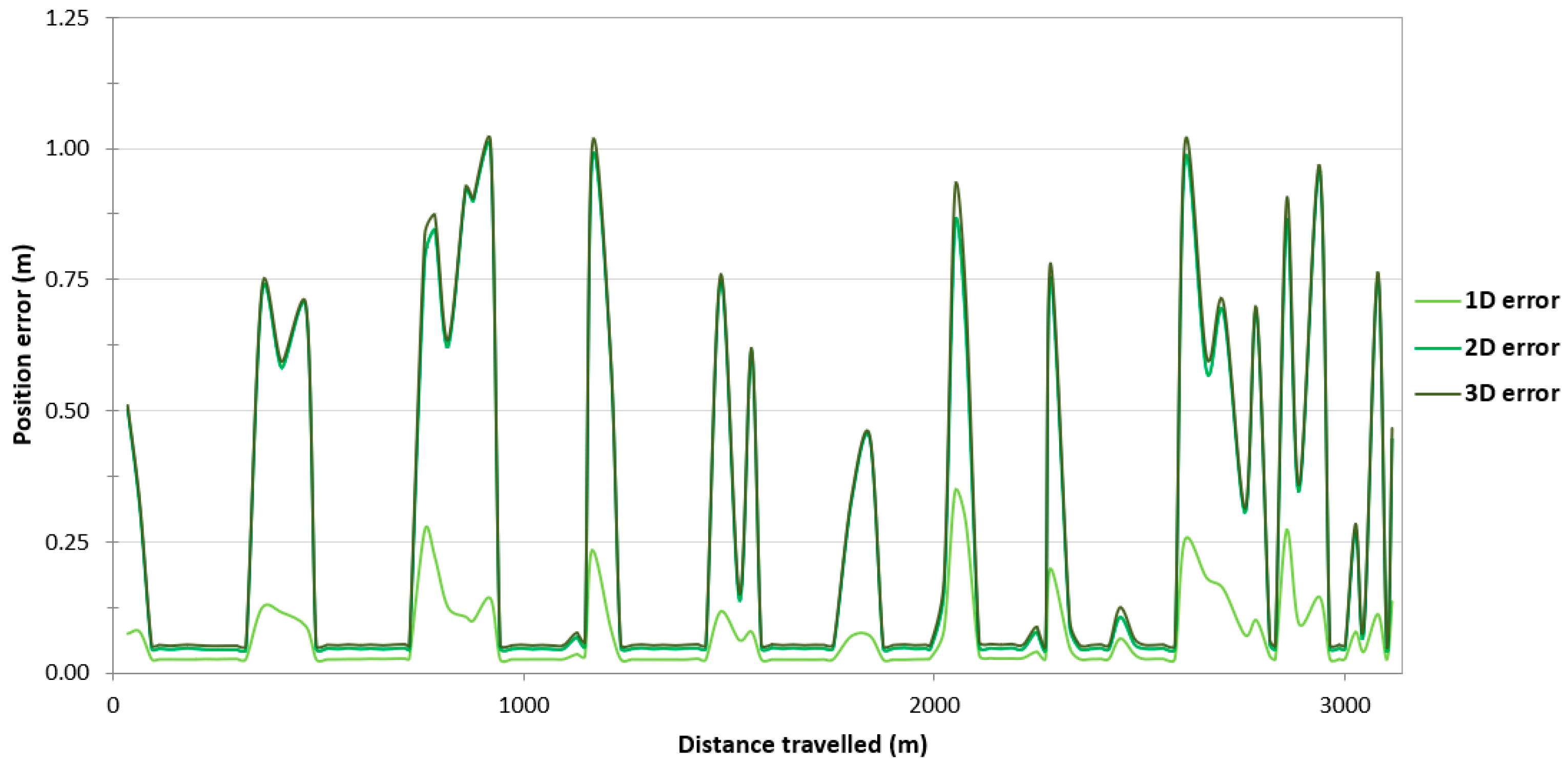
| RMS(ϕ) | 0.249 m | 0.241 m | 0.258 m | 0.276 m |
| RMS(λ) | 0.249 m | 0.241 m | 0.258 m | 0.276 m |
| RMS(h) | 0.081 m | 0.087 m | 0.089 m | 0.075 m |
| DRMS(2D) | 0.352 m | 0.341 m | 0.364 m | 0.390 m |
| 2DRMS(2D) | 0.705 m | 0.683 m | 0.729 m | 0.781 m |
| DRMS(3D) | 0.362 m | 0.352 m | 0.375 m | 0.398 m |
| CEP(2D) | 0.049 m | 0.048 m | 0.048 m | 0.047 m |
| R68(2D) | 0.164 m | 0.113 m | 0.151 m | 0.203 m |
| R95(2D) | 0.877 m | 0.886 m | 0.901 m | 0.941 m |
| SEP(3D) | 0.056 m | 0.054 m | 0.054 m | 0.054 m |
| R68(3D) | 0.179 m | 0.130 m | 0.166 m | 0.220 m |
| R95(3D) | 0.895 m | 0.914 m | 0.919 m | 0.953 m |
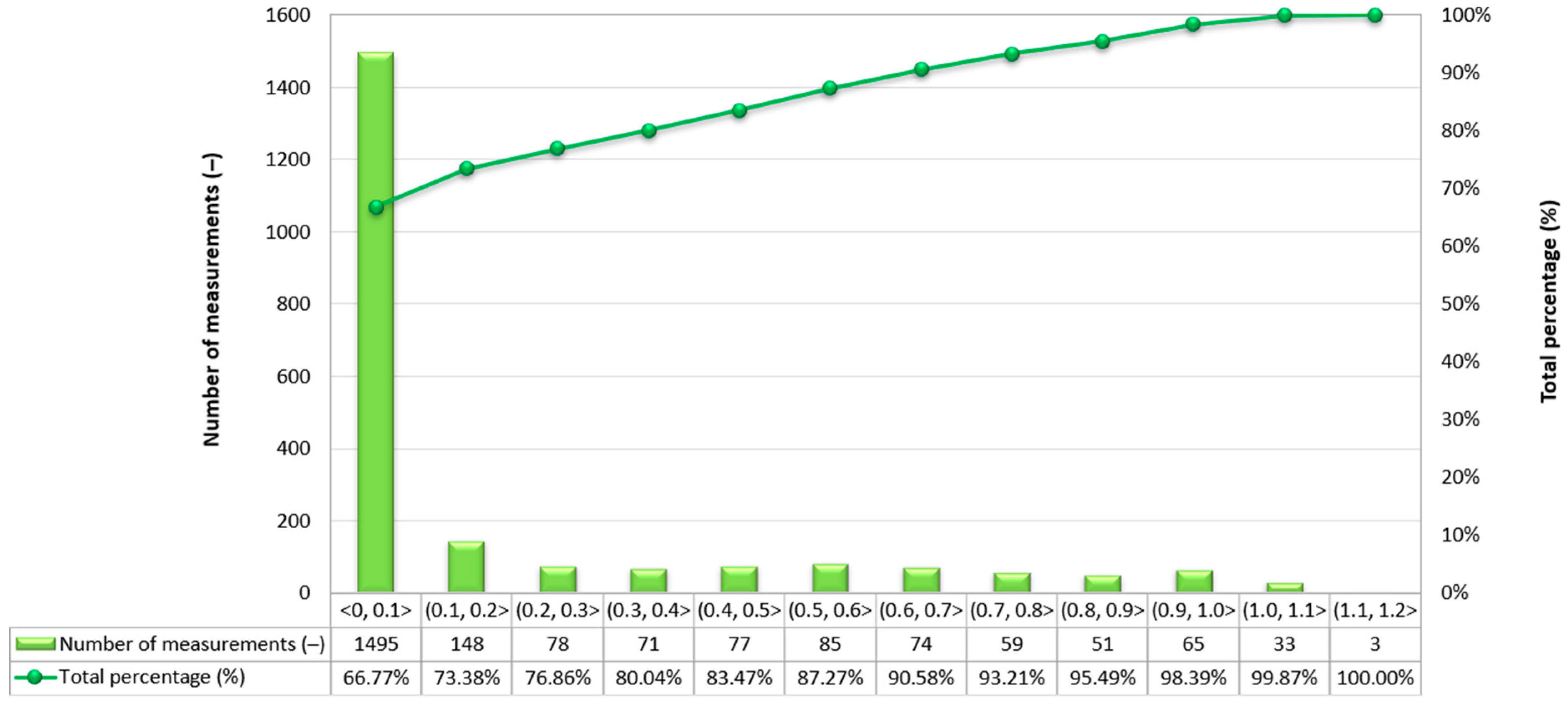
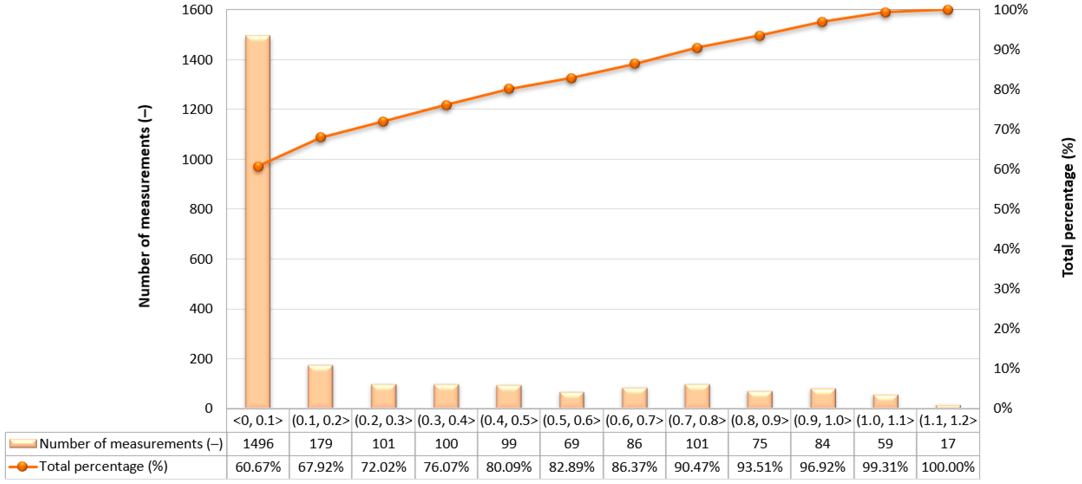
| Route Number | Positioning Availability (%) | |||
|---|---|---|---|---|
| Exclusive Order | Special Order | 1a/1b Orders | Order 2 | |
| 1 | 98.63 | 100 | 100 | 100 |
| 2 | 98.39 | 100 | 100 | 100 |
| 3 | 96.99 | 100 | 100 | 100 |
| 4 | 96.86 | 1000 | 100 | 100 |
Disclaimer/Publisher’s Note: The statements, opinions and data contained in all publications are solely those of the individual author(s) and contributor(s) and not of MDPI and/or the editor(s). MDPI and/or the editor(s) disclaim responsibility for any injury to people or property resulting from any ideas, methods, instructions or products referred to in the content. |
© 2024 by the author. Licensee MDPI, Basel, Switzerland. This article is an open access article distributed under the terms and conditions of the Creative Commons Attribution (CC BY) license (https://creativecommons.org/licenses/by/4.0/).
Share and Cite
Specht, M. Testing and Analysis of Selected Navigation Parameters of the GNSS/INS System for USV Path Localization during Inland Hydrographic Surveys. Sensors 2024, 24, 2418. https://doi.org/10.3390/s24082418
Specht M. Testing and Analysis of Selected Navigation Parameters of the GNSS/INS System for USV Path Localization during Inland Hydrographic Surveys. Sensors. 2024; 24(8):2418. https://doi.org/10.3390/s24082418
Chicago/Turabian StyleSpecht, Mariusz. 2024. "Testing and Analysis of Selected Navigation Parameters of the GNSS/INS System for USV Path Localization during Inland Hydrographic Surveys" Sensors 24, no. 8: 2418. https://doi.org/10.3390/s24082418