

Emission Spectroscopy-Based Sensor System to Correlate the In-Cylinder Combustion Temperature of a Diesel Engine to NOx Emissions

 ,
, 
Abstract
:1. Introduction
2. Setup
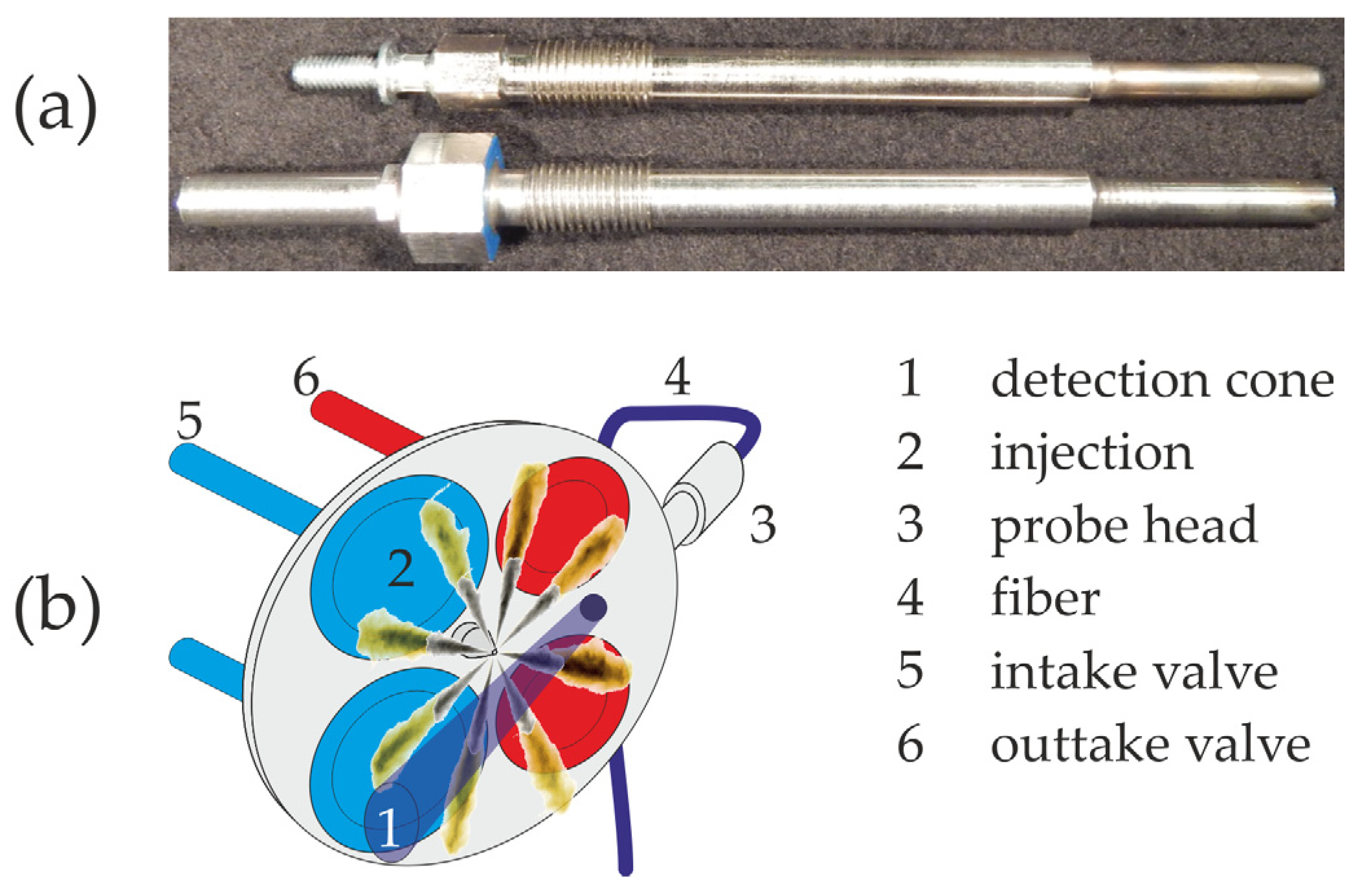
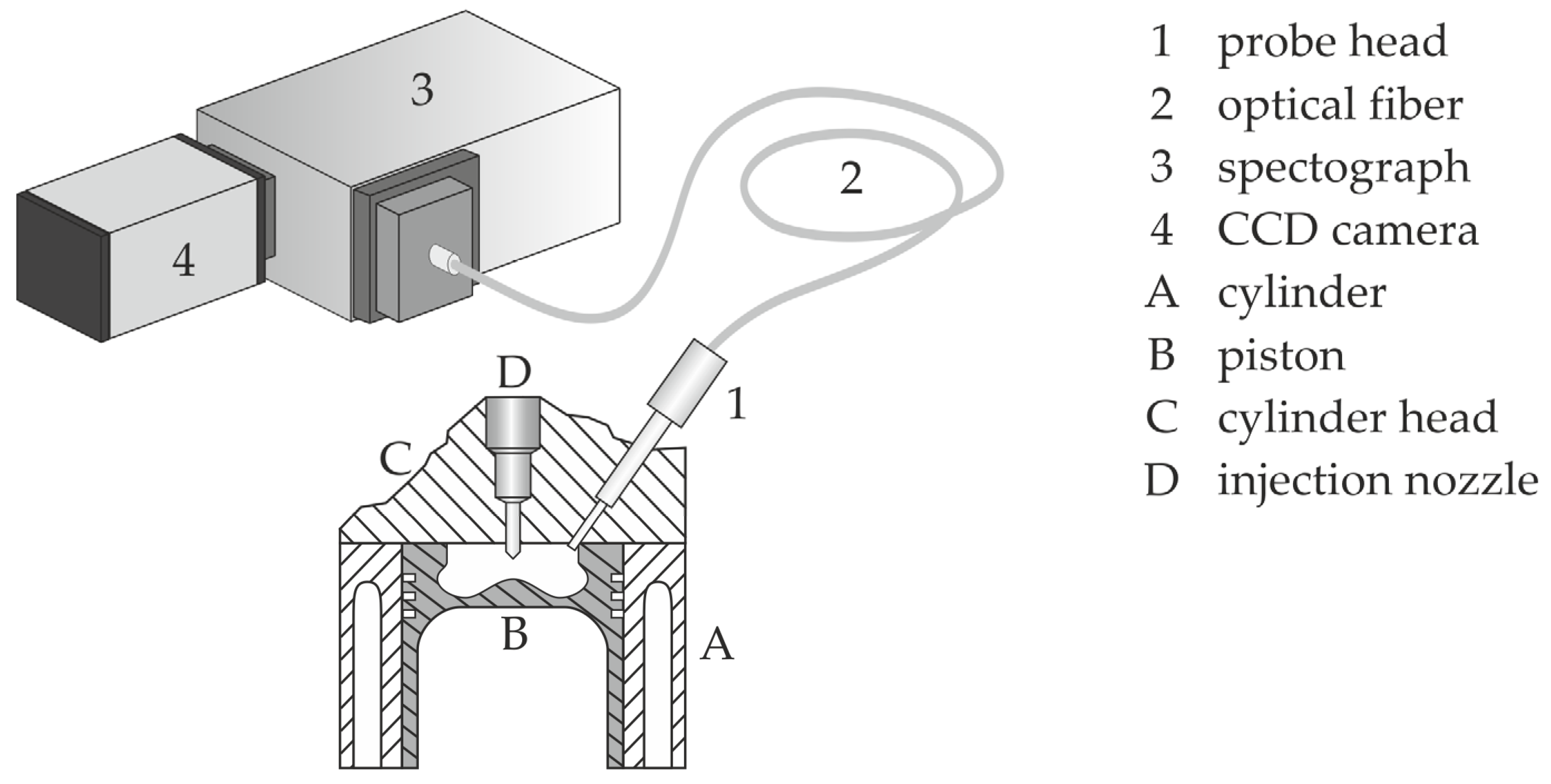
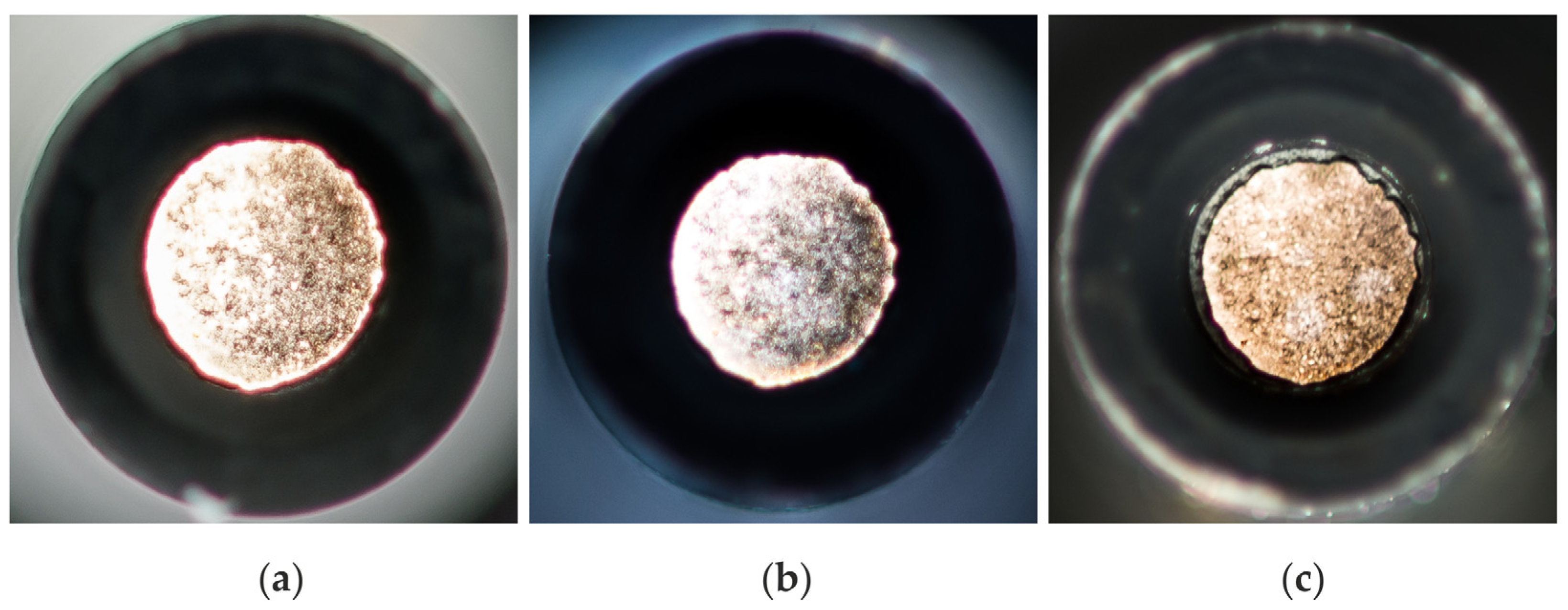
2.1. Optical Setup
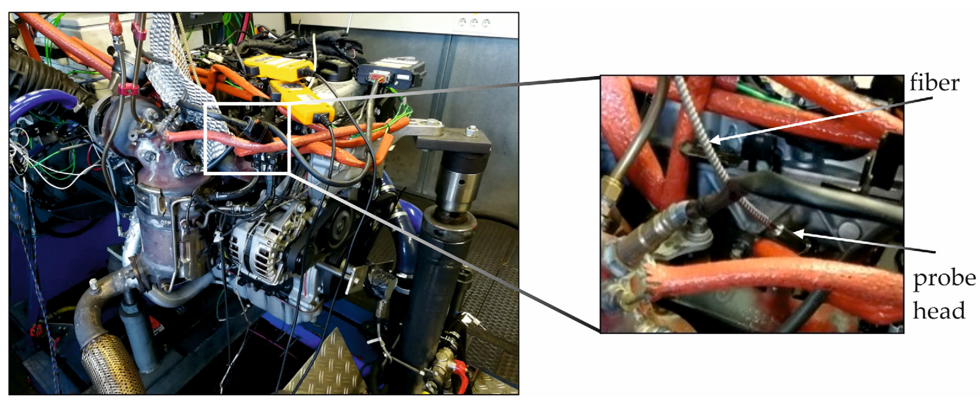
2.2. Engine Setup
3. Data Evaluation
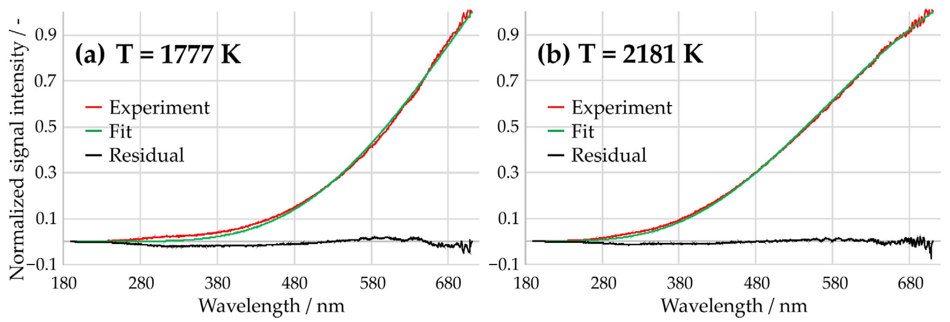
4. Results and Discussion
5. Summary
Author Contributions
Funding
Institutional Review Board Statement
Informed Consent Statement
Data Availability Statement
Acknowledgments
Conflicts of Interest
References
- World Energy Outlook. Available online: https://www.iea.org/reports/world-energy-outlook-2020 (accessed on 25 November 2020).
- Pischinger, R.; Klell, M.; Sams, T. Thermodynamik der Verbrennungskraftmaschine. Der Fahrzeugantrieb, 3rd ed.; Springer: Vienna, Austria, 2009; pp. 279–286. [Google Scholar]
- Warnatz, J.; Maas, U.; Dibble, R.W. Verbrennung: Physikalisch-Chemische Grundlagen, Modellierung und Simulation, Experimente, Schadstoffentstehung, 3rd ed.; Springer: Berlin, Germany, 2001. [Google Scholar]
- Zeldovich, Y.B. The oxidation of nitrogen in combustion explosions. Acta Physicochim. 1946, 21, 577–628. [Google Scholar]
- Zeldovich, Y.B.; Sadovnikov, P.Y.; Frank-Kamenetskii, D.A. Oxidation of Nitrogen in Combustion; Publishing House of the Academy of Sciences of USSR: Moscow, Russia, 1947. [Google Scholar]
- Heywood, J.B. Internal Combustion Engine Fundamentals; McGraw-Hill: New York, NY, USA, 2002. [Google Scholar]
- Hassan, Q.H.; Ridha, C.S.A.; Hafedh, K.A.H. The impact of Methanol-Diesel compound on the performance of a Four-Stroke CI engine. Mater. Today Proc. 2021, 42, 1993–1999. [Google Scholar] [CrossRef]
- Pandey, S. A critical review: Application of methanol as a fuel for internal combustion engines and effects of blending methanol with diesel/biodiesel/ethanol on performance, emission and combustion characteristics of engines. Heat Transf. 2022, 51, 3334–3352. [Google Scholar] [CrossRef]
- El-Seesy, A.I.; Waly, M.S.; Nasser, A.; El-Zoheiry, R.M. Improvement of the combustion, emission, and stability features of diesel-methanol blends using n-decanol as cosolvent. Sci. Rep. 2022, 12, 18963. [Google Scholar] [CrossRef] [PubMed]
- Baratta, M.; Finesso, R.; Misul, D.; Spessa, E. Comparison between internal and external EGR performance on a heavy duty Diesel engine by means of a refined 1D fluid-dynamic engine model. SAE Int. J. Engines 2015, 8, 1977–1992. [Google Scholar] [CrossRef]
- Finesso, R.; Hardy, G.; Maino, C.; Marello, O.; Spessa, E. A new control-oriented semi-empirical approach to predict engine-out NOx emissions in a Euro VI 3.0 L Diesel engine. Energies 2017, 10, 1978. [Google Scholar] [CrossRef]
- Finesso, R.; Hardy, G.; Marello, O.; Spessa, E.; Yang, Y. Model-based control of BMEP and NOx emissions in a Euro VI 3.0 L Diesel engine. SAE Int. J. Engines 2017, 10, 2288–2304. [Google Scholar] [CrossRef]
- Manchur, T.; Checkel, M. Time Resolution Effects on Accuracy of Real-Time NOX Emissions Measurements; SAE Technical Paper; Society of Automotive Engineers (SAE): Warrendale, PA, USA, 2005; 2005-01-0674. [Google Scholar]
- Andersson, M.; Johansson, B.; Hultqvist, A.; Noehre, C. A Predictive Real Time NOX Model for Conventional and Partially Premixed Diesel Combustion; SAE Technical Paper; Society of Automotive Engineers (SAE): Warrendale, PA, USA, 2006; 2006-01-3329. [Google Scholar]
- Asprion, J.; Chinellato, O.; Guzzella, L. A fast and accurate physics-based model for the NOX emissions of Diesel engines. Appl. Energy 2013, 103, 221–233. [Google Scholar] [CrossRef]
- Timoney, D.J.; Desantes, J.; Hernández, M.L.; Lyons, C.M. The development of a semi-empirical 468 model for rapid NOX concentration evaluation using measured in-cylinder pressure in diesel engines. Proc. Inst. Mech. Eng. Part D-J. Automob. Eng. 2005, 219, 621–631. [Google Scholar] [CrossRef]
- Birkigt, A.; Michels, K.; Theobald, J.; Seeger, T.; Gao, Y.; Weikl, M.C.; Wensing, M.; Leipertz, A. Investigation of compression temperature in highly charged spark-ignition engines. Int. J. Engine Res. 2011, 12, 282–292. [Google Scholar] [CrossRef]
- Zhao, H.; Ladommatos, N. Optical diagnostics for soot and temperature measurement in diesel engines. Prog. Energy Combust. Sci. 1998, 24, 221–255. [Google Scholar] [CrossRef]
- Schulz, C.; Sick, V. Tracer-LIF diagnostics: Quantitative measurement of fuel concentration, temperature and fuel/air ratio in practical combustion systems. Prog. Energy Combust. Sci. 2005, 31, 75–121. [Google Scholar] [CrossRef]
- Taschek, M.; Egermann, J.; Schwarz, S.; Leipertz, A. Quantitative analysis of the near-wall mixture formation process in a passenger car direct-injection Diesel engine by using linear Raman spectroscopy. Appl. Opt. 2005, 44, 6606–6615. [Google Scholar] [CrossRef] [PubMed]
- Williams, B.; Edwards, M.; Stone, R.; Williams, J.; Ewart, P. High precision in-cylinder gas thermometry using Laser Induced Gratings: Quantitative measurement of evaporative cooling with gasoline/alcohol blends in a GDI optical engine. Combust. Flame 2014, 161, 270–279. [Google Scholar] [CrossRef]
- Rieker, G.B.; Li, H.; Liu, X.; Liu, J.T.; Jeffries, J.B.; Hanson, R.K.; Allen, M.G.; Wehe, S.D.; Mulhall, P.A.; Kindle, H.S.; et al. Rapid measurements of temperature and H2O concentration in IC engines with a spark plug-mounted diode laser sensor. Proc. Combust. Inst. 2007, 31, 3041–3049. [Google Scholar] [CrossRef]
- Hall, M.J.; Koenig, M. A fiber-optic probe to measure precombustion in-cylinder fuel-air ratio fluctuations in production engines. Proc. Combust. Inst. 1996, 26, 2613–2618. [Google Scholar] [CrossRef]
- Ishida, M.; Sakaguchi, D.; Luo, G. Turbulence Measurement in Diesel Combustion by Optical Fiber Thermometer; SAE Technical Paper; SAE International: Warrendale, PA, USA, 1997; Volume 972915, pp. 121–132. [Google Scholar]
- Maliha, M.; Kraljevic, I.; Wytrykus, F.; Bertola, A. Innermotorische optische Rußuntersuchungen bei Ottomotoren. MTZ Motortech. Z. 2020, 81, 28–37. [Google Scholar] [CrossRef]
- Vattulainen, J.; Nummela, V.; Hernberg, R.; Kytölä, J. A system for quantitative imaging diagnostics and its application to pyrometric in-cylinder flame-temperature measurements in large diesel engines. Meas. Sci. Technol. 2000, 11, 103–119. [Google Scholar] [CrossRef]
- Antoni, C.; Peters, N. Cycle Resolved Emission Spectroscopy for IC Engines; SAE Technical Paper; SAE International: Warrendale, PA, USA, 1997; Volume 972917, pp. 145–156. [Google Scholar]
- Block, B.; Möser, P.; Hentschel, W. Time-resolved emission spectroscopy for the combustion analysis of series production engines. Opt. Eng. 1997, 36, 1183–1190. [Google Scholar] [CrossRef]
- Kobayashi, S.; Komori, M.; Nakahira, T.; Sakai, T.; Tsujimura, K. Measurement of Flame Temperature Distribution in D.I. Diesel Engine with High Pressure Fuel Injection; SAE Technical Paper; SAE International: Warrendale, PA, USA, 1992; Volume 920692, pp. 173–182. [Google Scholar]
- Mancaruso, E.; Merola, S.S.; Vaglieco, B.M. Study of the multi-injection combustion process in a transparent direct injection common rail diesel engine by means of optical techniques. Int. J. Engine Res. 2008, 9, 483–498. [Google Scholar] [CrossRef]
- Neupane, S.; Jatana, G.S.; Lutz, T.P.; Partrige, W.P. Development of a multi-spectral pyrometer sensor for high-speed transient surface-temperature measurements in combustion-relevant harsh environments. Sensors 2023, 23, 105. [Google Scholar] [CrossRef] [PubMed]
- di Stasio, S.; Massoli, P. Influence of the soot property uncertainties in temperature and volume-fraction measurements by two-colour pyrometry. Meas. Sci. Technol. 1994, 5, 1453–1465. [Google Scholar] [CrossRef]
- Snelling, D.R.; Thomson, K.A.; Smallwood, G.J.; Gülder, Ö.L.; Weckman, E.J.; Fraser, R.A. Spectrally resolved measurement of flame radiation to determine soot temperature and concentration. AIAA J. 2002, 40, 1789–1795. [Google Scholar] [CrossRef]
- Weikl, M.C.; Seeger, T.; Wendler, M.; Sommer, R.; Beyrau, F.; Leipertz, A. Validation experiments for spatially resolved one-dimensional emission spectroscopy temperature measurements by dual-pump CARS in a sooting flame. Proc. Combust. Inst. 2009, 32, 745–752. [Google Scholar] [CrossRef]
- Toro, C.; Torres, S.; Parra, V.; Fuentes, R.; Castillo, R.; Diaz, W.; Reyes, G.; Balladares, E.; Parra, R. On the detection of spectral emissions of iron oxides in combustion experiments of pyrite concentrates. Sensors 2020, 20, 1284. [Google Scholar] [CrossRef] [PubMed]
- Block, B.; Hentschel, W.; Ertmer, W. Pyrometric determination of temperature in rich flames and wavelength dependence of their emissivity. Combust. Flame 1998, 114, 359–369. [Google Scholar] [CrossRef]
- Stull, V.R.; Plass, G.N. Emissivity of dispersed carbon particles. J. Opt. Soc. Am. 1960, 50, 121–129. [Google Scholar] [CrossRef]
- Goulay, F.; Schrader, P.E.; Michelsen, H.A. Effect of the wavelength dependence of the emissivity on inferred soot temperatures measured by spectrally resolved laser-induced incandescence. Appl. Phys. B Lasers Opt. 2010, 100, 655–663. [Google Scholar] [CrossRef]
- Michelsen, H.A. Understanding and predicting the temporal response of laser-induced incandescence from carbonaceous particles. J. Chem. Phys. 2003, 118, 7012–7045. [Google Scholar] [CrossRef]
- Marquardt, D.W. An algorithm for least-squares estimation of nonlinear parameters. J. Soc. Ind. Appl. Math. 1963, 11, 431–441. [Google Scholar] [CrossRef]
- Schlüter, S.; Krischke, F.; Popovska-Leipertz, N.; Seeger, T.; Breuer, G.; Jeleazcov, C.; Schüttler, J.; Leipertz, A. Demonstration of a signal enhanced fast Raman sensor for multi-species gas analyses at a low pressure range for anesthesia monitoring. J. Raman Spectrosc. 2015, 46, 708–715. [Google Scholar] [CrossRef]
- Egermann, J.; Jonuscheit, J.; Leipertz, A.; Seeger, T. Untersuchung von diodenlaserbasierten Mehrkomponenten-Konzentrationsmesssystemen zur Gasanalyse: Investigation of diode laser-based multi-species gas sensor concepts. Tech. Mess. 2001, 68, 400–405. [Google Scholar] [CrossRef]
- Schlüter, S.; Seeger, T.; Popovska-Leipertz, N.; Leipertz, A. Atemzyklusgenaues Anästhesiegas-Monitoring mit einer laserbasierten Raman-Sonde unter klinischen Bedingungen. Tech. Mess. 2016, 83, 289–299. [Google Scholar] [CrossRef]
- Feldhaus, F.; Schmitz, I.; Seeger, T. Emission spectroscopy based sensor developed for engine testing. Tech. Mess. 2017, 84, 13–22. [Google Scholar] [CrossRef]


| Parameter | Description | Unit |
|---|---|---|
| T | Temperature | K |
| Wavelength | nm | |
| N | Number of soot particles | - |
| D | Soot particle diameter | nm |
| c | Speed of light | m/s |
| h | Planck constant | J s |
| k | Boltzmann constant | J/K |
| Engine Parameter | Settings |
|---|---|
| Pilot injection | Pilot 1 off |
| Pilot 2 off | |
| Pilot 1 + 2 off | |
| Pilot 1 + 50% | |
| Pilot 2 + 50% | |
| CA 50 | 2 °CA BTDC |
| 5 °CA ATDC | |
| EGR rate | 0% |
| 25% | |
| 50% | |
| 75% | |
| 100% |
Disclaimer/Publisher’s Note: The statements, opinions and data contained in all publications are solely those of the individual author(s) and contributor(s) and not of MDPI and/or the editor(s). MDPI and/or the editor(s) disclaim responsibility for any injury to people or property resulting from any ideas, methods, instructions or products referred to in the content. |
© 2024 by the authors. Licensee MDPI, Basel, Switzerland. This article is an open access article distributed under the terms and conditions of the Creative Commons Attribution (CC BY) license (https://creativecommons.org/licenses/by/4.0/).
Share and Cite
Wultschner, J.; Schmitz, I.; Révidat, S.; Ullrich, J.; Seeger, T. Emission Spectroscopy-Based Sensor System to Correlate the In-Cylinder Combustion Temperature of a Diesel Engine to NOx Emissions. Sensors 2024, 24, 2459. https://doi.org/10.3390/s24082459
Wultschner J, Schmitz I, Révidat S, Ullrich J, Seeger T. Emission Spectroscopy-Based Sensor System to Correlate the In-Cylinder Combustion Temperature of a Diesel Engine to NOx Emissions. Sensors. 2024; 24(8):2459. https://doi.org/10.3390/s24082459
Chicago/Turabian StyleWultschner, Jürgen, Ingo Schmitz, Stephan Révidat, Johannes Ullrich, and Thomas Seeger. 2024. "Emission Spectroscopy-Based Sensor System to Correlate the In-Cylinder Combustion Temperature of a Diesel Engine to NOx Emissions" Sensors 24, no. 8: 2459. https://doi.org/10.3390/s24082459