4.1. Basic Design
Figure 2 shows the proposed adaptive channel allocation scheme for WAVE. RSUs periodically transmit WSA messages containing information about the services they offer through the control channel. In this process, RSUs include channel adjustment parameters in the WSA encompassing the CCHI, SCHI, guard interval length information (guard interval), and update time information (update time).
Before connecting to a specific RSU, OBUs in vehicles continuously monitor the control channel. By doing this, they can receive advertisement messages via the control channel upon entering the broadcast range of a specific RSU. After receiving the advertisement message, the OBU undergoes a synchronization process with the RSU. Subsequently, it begins channel switching between the control and service channels based on the channel adjustment parameters.
RSUs and OBUs in vehicles exchange data through the control channel and service channel while performing channel switching. During this data exchange, RSUs monitor the congestion level of the current CCH and SCH based on the amount of data traffic being exchanged. The congestion level of the channels, according to the volume of data traffic, can be determined by considering the average queuing delay of packets transmitted on each of the control and service channels at the MAC level, as well as the number of transmission failures due to data collisions.
If the monitored congestion level of a channel is higher on either the CCH or the SCH, the channel coordination parameter is adjusted to increase the interval length of the more congested channel and decrease the interval length of the less congested channel. However, since the CCH is more crucial due to the transmission of management messages like service advertisements and timing information, as well as high-priority messages, its interval length is adjusted to be above a minimum interval threshold, ensuring its essential functions are maintained.
The modified channel coordination parameters are transmitted from the RSU to the OBU. Channel switching is adjusted according to these adjusted channel coordination parameters, and data exchange continues through the adjusted CCH and SCHs. Monitoring the effectiveness of this data exchange, as well as the congestion levels based on the amount of data traffic in the CCH and SCHs, continues as long as the OBU remains within the broadcast range of the RSU.
4.2. The Proposed Adaptive Resource Allocation Scheme
An adaptive channel coordination scheme to improve the transmission efficiency of messages is proposed. Firstly, if a device intends to use services during the SCHI, it broadcasts information about the service during the CCHI through WSA messages. At this time, the device uses the existing extended field of the WSA message to indicate the data size of the service. Additionally, when allocating the SCH, all stations use an SCH allocation table to prevent service data from being biased towards one side. The SCH allocation table records the total expected service data for each SCH by examining WSA messages. The SCH allocation table is as shown in
Table 1.
When constructing the WSA message, service providers check the SCH allocation table for each SCH number and the total amount of expected infotainment data. In
Table 1, the service provider selects SCH 2, which has the smallest value, and adds the data size of this service to the total expected service data in their SCH allocation table. Other OBUs that receive this WSA message check the extension and service information fields of the WSA message to add the service data size to their own SCH allocation table. If these OBUs wish to use this service during the next SCHI, they add an ACK message to the next beacon message. This ACK message must include information such as user priority and data size if the OBU intends to send some data using this service during the next SCHI. The information includes (i) the number of stations participating in channel contention during the next SCHI, (ii) the provider service identifier (PSID) to identify the type of infotainment service, and (iii) the service priority field in the service field of the WSA message received during the CCHI.
The RSU uses the information to calculate the length of the transmission opportunity (TXOP) and the values for the next CCHI and SCHI and CWmin at the end of the CCHI. These modified values are then broadcast before the end of this CCHI.
The TXOP limit value is calculated as the total amount of service data divided by the number of stations that sent ACK messages. The length of the next CCHI and SCHI can be estimated based on the current amount of safety-related data traffic and the expected amount of infotainment data traffic. The amount of current safety-related data traffic, TD
CCH, is calculated as follows [
27]:
Here, E{L} is the average length of a safety packet, λ is the transmission frequency of safety packets, and α is a weight that considers the additional time due to channel collisions and the transmission of WSA packets.
Additionally, the estimated amount of infotainment data traffic is nearly equal to the maximum of the total estimated infotainment data for each AC in the RSU’s SCH allocation table at the end of the current CCHI. Therefore, the next lengths of the CCHI and SCHI, T
CCH and T
SCH, respectively, are adaptively adjusted as follows:
Here, TDSCH is the expected amount of infotainment data traffic and β is a weighting factor for safe driving. The loss of safety-related messages can have a critical impact on driver and passenger safety. Therefore, the value of β is predefined to be greater than 1.
To maintain the advantages of competitive channel access while reducing service data collisions and increasing service data throughput, CWmin is adjusted according to the number of service providers and the type of infotainment service offered by the RSU. When assigning the adaptive CWmin value, the RSU allocates the optimal CWmin in terms of total throughput. The method for optimizing CWmin is explained in detail in the following section.
4.3. The Proposed CW Adjustment Scheme Using Q-Learning
Figure 3 shows the timing diagram for the connection configuration between the RSU and OBU. The OBU sends a beacon message to the RSU that includes the OBU’s physical and logical information, and the RSU uses this beacon message to initiate authentication and registration processes. The RSU then sends a response to the beacon message.
Upon receiving a response from the RSU, the OBU waits for an interframe space (IFS) duration. Afterward, the OBU checks if the channel between the RSU and OBU is idle. If the channel is not idle, the OBU waits further during the IFS time.
If the channel between the RSU and OBU is idle, the OBU waits for a period within the CW range before transmitting packet data to the RSU. This process helps prevent collisions that could occur when multiple OBUs transmit data simultaneously. The size of the CW must satisfy the following conditions:
It should not increase packet transmission delays.
It should not be unnecessarily large to avoid missing TXOPs.
It should require minimal computational power so as not to strain the processor.
The CSMA/CA mechanism used in existing IEEE 802.11p and IEEE 1609.4 standards sets the channel access time of multiple devices randomly to avoid overlapping and thus prevent collisions. Therefore, each device maintains a small CW. However, recent studies show that setting a small CW is a major cause of packet collisions in the IEEE 802.11p network [
28,
29].
IEEE 802.11p and IEEE 1609.4 communication protocols manage vehicles broadcasting beacon and safety messages in the CCH interval and use the backoff algorithm to reduce collisions. In the case of broadcast communication, there is no way to check for collisions, so regardless of the success of a transmission, a fixed CWmin must be used, and a random value is selected from [0, CWmin], followed by a wait for that duration (backoff delay) before broadcasting. Therefore, in a broadcast communication environment, when multiple nodes transmit data simultaneously, frequent transmission failures can occur due to collisions, necessitating the need to adjust the size of the CW to reduce the number of collisions and improve the reception success rate. The adaptive adjustment of the CW in the CCH using broadcast communication produces better performance than the existing method.
To address the abovementioned challenges, this paper proposes a reinforcement learning (RL)-based channel access technique that enables the efficient exchange of data packets among a large number of vehicles.
Figure 4 illustrates the structure of the proposed CW adjustment technique, and
Figure 5 shows the proposed channel structure.
In the CCH, broadcast communication is performed and, in this case, ACK messages are not received. Therefore, in the proposed technique, the frame structure of the WAVE standard can include a message exchange interval (an interval for receiving ACKs).
As depicted in
Figure 5, at the end of the CCHI, the frame structure can be modified to include an interval for unicast communication in the CCH for a duration of T
CSV (CW suitability verification interval, CSV interval). During this time, each station (STA) can select one of its neighboring STAs to send and receive data (current CW check packet). An STA represents a device performing communication.
In the proposed scheme, the initial CW can be set to CWmin. If STA A does not receive an ACK, instead of requesting retransmission of the ACK, STA A considers it a transmission failure. If STA A receives an ACK, it considers the transmission successful in the current contention window.
The CSV interval is determined based on Equation (3).
In this context, TDIFS represents the DCF interframe space time, CWmax is the maximum CW value, and Slottime is the time for a slot as defined in IEEE 802.11p (for example, the slottime for OFDM PHY defined in the IEEE 802.11p standard is 9 μs). E[TData] is the expected time taken to transmit data (i.e., the current CW check packet) used in the CSV interval. TSIFS is the short interframe space time, and E[TACK] is the expected time taken to receive an ACK. In the proposed scheme, E[TData] = (size of data)/(data rate), and E[TACK] = (size of ACK)/(data rate).
4.4. CW Update Scheme Using a Q-Learning Model
In the proposed technique, the CW can be updated based on a Q-learning model. The Q-learning model is designed using the following equation:
where s
t represents the state (the size of the CW) at time t, a
t is the probability of action at time t, α is the learning rate, γ is the discount factor, and r
t is the reward value at time t. Specifically, s
t at time t could be 3, 7, 15, 31, 63, 127, or 255. In this case, CW
min could be 3. Moreover, a
t could involve actions to reduce, maintain, or increase the CW. For learning based on new information, α is close to 1. Meanwhile, γ as the discount factor can be close to 1 for learning towards higher rewards and close to 0 for learning towards current rewards. Additionally, r
t as the reward value at time t can be set to 1 if an ACK message is received and −1 if it is not received.
If the CW is at minimum, it can set the initial Q-table. Specifically, the first STA can set the CW during the initial broadcast communication process to CW
min (CW = 3). In this case, the Q-table includes rows 1 to 7 for the CW size and columns 1 to 3 for the backoff exponent (BE) and is used to decide the action for changing the CW size. Specifically, the initial Q-table representing the Q values for the CW in the aforementioned initial communication process is as shown in
Table 2.
In the proposed scheme, CW can be updated based on the Q-learning model, with the BE being a parameter that decides the action for changing the size of the CW, as determined by Equation (5).
When the action determined by the Q-table is BE − 1, the first STA reduces the size of the contention window; if it is BE, the STA maintains the size; and if it is BE + 1, the STA increases the size. Moreover, as the contention window changes through the Q-learning model, the STA can update the Q-table as depicted in
Table 2. In the proposed technique, with each update, there is a 0.9 probability of choosing the action corresponding to the column with the highest value among BE − 1, BE, and BE + 1 in the updated Q-table. There is also a 0.1 probability of randomly choosing any column corresponding to BE − 1, BE, or BE + 1.
By adding randomness to the change in the CW, the technique ensures dynamic adjustment. In cases where the updated Q-table has identical values for the row corresponding to the CW, the Q-learning model is designed to reduce the size of the contention window, thus preventing its expansion. For example, if the values in columns BE − 1, BE, and BE + 1 of the current state in the Q-table are all the same, the column corresponding to BE − 1 can be chosen as the action.
In cases where two of the three values in the updated Q-table are the same, and the third value is smaller, the STA can choose the action corresponding to the column of the two identical values. For example, if BE − 1 and the BE columns have the same values and BE + 1 is smaller, the column corresponding to BE − 1 can be chosen as the action.
The proposed scheme allows choosing an action that reduces the size of the CW among two identical actions. For instance, if the first largest value is in the BE − 1 column and the second largest value is in the BE + 1 column, and the difference between these values is within a pre-set range, the column corresponding to BE − 1 can be chosen as the action. Even if the values corresponding to actions are different, if the difference between the largest and the second or third largest values is minimal, the STA can set the action towards reducing the size of the contention window.
As an example, in the process of changing the contention window using the proposed technique when the initial state st
0 is 3, the initial action at
0 is BE, α is 0.6, and γ is 0.9 is examined. The initial state Q-table is as shown in
Table 3, with the value corresponding to the current state being one-third (marked in red).
In this scenario, assume for example that the first STA (device) fails to receive an ACK message from a second STA (another device), and a probability of 0.9 is selected. This means that the current state st0 is 3, and at0 is BE (maintaining the current state), so st1 could be a contention window size of 3 (maintaining the current state).
The Q-learning model can operate according to the following equation and update the Q-table accordingly:
In this case, since the first STA fails to receive an ACK message, rt+1 = −1. Also, this corresponds to the value when the contention window is 3 and the action is in the BE column, which has a value of one-third.
Furthermore,
is the maximum value of a for state st0, so it takes the value of one-third corresponding to the case when the CW is 3 and the action is in the BE column. Consequently,
(marked in red). Based on this, the updated Q-table is as shown in
Table 4 below.
Since the largest value from the row with a CW of 3 is one-seventh (in the BE + 1 column), at
1 can be chosen as the action corresponding to BE + 1 (i.e., an action to increase the CW size). The Q-table in the updated state is as shown in
Table 5 below, and in this case, the value corresponding to the current state is one-seventh (marked in red).
In this scenario, assuming that the first STA (device) fails to receive an ACK message from the second STA (another device), and a probability of 0.9 is selected, the current state s
t1 is 3, and at1 is BE + 1; hence, s
t2 changes to a contention window size of 7. The Q-learning model operates according to Equation (7) and updates the Q-table shown in
Table 5.
In this situation, since the first STA fails to receive an ACK message, rt+1 = −1. Also, corresponds to the scenario where the CW is 3 and the action is in the BE + 1 column, which has a value of one-seventh. Furthermore, is the maximum value of a for state st1, so it takes the value of one-seventh, corresponding to the scenario where the CW is 3 and the action is in the BE + 1 column.
Consequently,
(marked in red). Based on this, the updated Q-table is as shown in
Table 6 below.
Since the largest value for the row with a CW of 3 is −0.28667 (in the BE column), at2 can be chosen as the action corresponding to BE (i.e., an action to maintain the CW size). Through this process, the Q-table is updated, and the size of the contention window can be changed according to the updated Q-table.
4.5. The Sync Interval Adjustment by RSU
Figure 6 shows the WSA frame. The advertisement message (WSA) includes a header, Interval Info Element, provider service table, and a WAVE routing advertisement. The header is defined in the WAVE standard and can include an optional extension field. The WAVE Version can differentiate messages by incrementing the ‘change count’ each time a message is transmitted. The interval info element contains the WAVE element ID, length, control channel length information (CCHInterval), service channel length information (SCHInterval), Guard Interval, and Update Time.
The WAVE Element ID is chosen from one of the areas allocated for future use in the WAVE communication standard and indicates the location of the Interval Info Element. The Length represents the length of the content included in the Interval Info Element, with the value of the Length field pointing to the length of the channel coordination parameter. The channel coordination parameter includes the CCHInterval, SCHInterval, Guard Interval, and Update Time.
The Update Time indicates the timing of channel switching according to the channel coordination parameter, specifying when (coordinated universal time, UTC) the channel switching should occur. For example, if the update time is ‘0’, channel switching occurs at the start of the next second of absolute time as per the channel coordination parameter.
The WAVE Routing Advertisement involves the RSU transmitting its IP address to the OBU in the vehicle, which can then use the received IP address. However, this is optional and can be omitted if an IP address for use between the OBU and RSU has been predetermined.
Figure 7 shows a flowchart depicting the initial exchange process of the channel coordination parameters in the proposed scheme.
The RSU transmits an advertisement message to the OBU in the vehicle, which includes information about the services it offers and the channel coordination parameters. Upon receiving this advertisement message, the OBU decides whether to receive services from the RSU. If it decides to receive services, the OBU synchronizes its timing with the RSU. Subsequently, the RSU transmits advertisement messages and data through the CCH and SCH. While transmitting data, the RSU periodically monitors the real-time congestion levels of the CCH and SCH based on the amount of data traffic. If the congestion level is high in one channel, the RSU adjusts the channel coordination parameters to increase the interval length of the congested channel. The adjusted channel coordination parameters are included in a new interval information response message and transmitted to the OBU through the CCH. The OBU and the RSU then perform channel switching in accordance with the update time information of the adjusted channel coordination parameters. As a result, the length of the channel with high congestion is increased, and the length of the channel with low congestion is decreased.
Figure 8 shows a flowchart depicting the process of changing the channel coordination parameters in the proposed intelligent resource allocation scheme.
In the scenario shown in
Figure 8, the RSU detects high congestion in the CCH. The RSU creates a new interval information element to increase the length of the CCHI. Subsequently, it broadcasts the WSA containing the new interval information element. If the update time information of the adjusted channel coordination parameters is ‘0’, the adjusted channel coordination parameters are applied from the start of the next absolute time, increasing the length of the CCH and decreasing the length of the SCH for channel switching. The OBUs that receive the new interval information element resynchronize with the RSU and smoothly communicate during the extended CCH time interval.
4.6. Sync Interval Adjustment by OBU
When an OBU detects congestion, it must also inform the RSU. During congestion, the OBU sends an Interval Adjustment Request message to the RSU. Upon receiving the Interval Adjustment Request message, the RSU generates channel coordination parameters, including CCHInterval, SCHInterval, Guard Interval, and Update Time. The RSU then broadcasts an Interval Adjustment Response message containing the new channel coordination parameters. The OBU, after receiving the response message, undergoes a synchronization process to align its timing with the RSU. Then, it begins channel switching between the control and service channels according to the received channel coordination parameters.
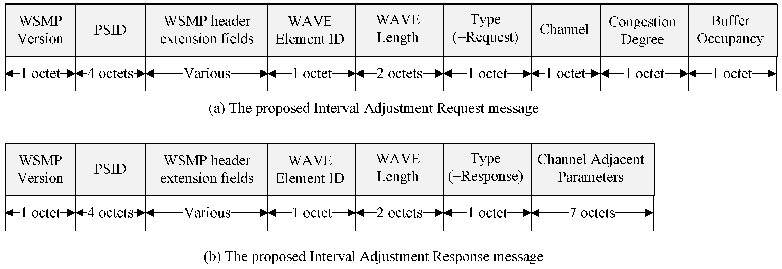
Figure 9 shows the structure of the Interval Adjustment messages.
Figure 9a shows the proposed Interval Adjustment Request message. The WSMP version field indicates the WAVE protocol version. The PSID is a numerical field used in the IEEE 1609 standard, utilized for identifying specific applications. To access WAVE services, an application must be registered with a unique PSID. WAVE provider devices use the PSID in their announcement messages to indicate the provision of specific applications. The WSMP header extension field defines the channel used for communication and determines the length of the WSMP header, represented by the WAVE Element ID field and the data field. The Channel field indicates the channel where congestion occurred. The Congestion Degree field contains the congestion degree calculated by the device, and the Buffer Occupancy field includes the buffer occupancy calculated by the device.
Figure 9b displays the structure of the proposed Interval Adjustment Response message. The Type field indicates whether the interval information element is a request or a response, with the Type in the Interval Adjustment Response message corresponding to a response. The channel adjustment parameter field includes CCHInterval, SCHInterval, Guard Interval, and Update Time. The Update Time in the Interval Information Response message is ‘0’, so the channel coordination parameters are applied from the start of the next absolute time, enabling channel switching.
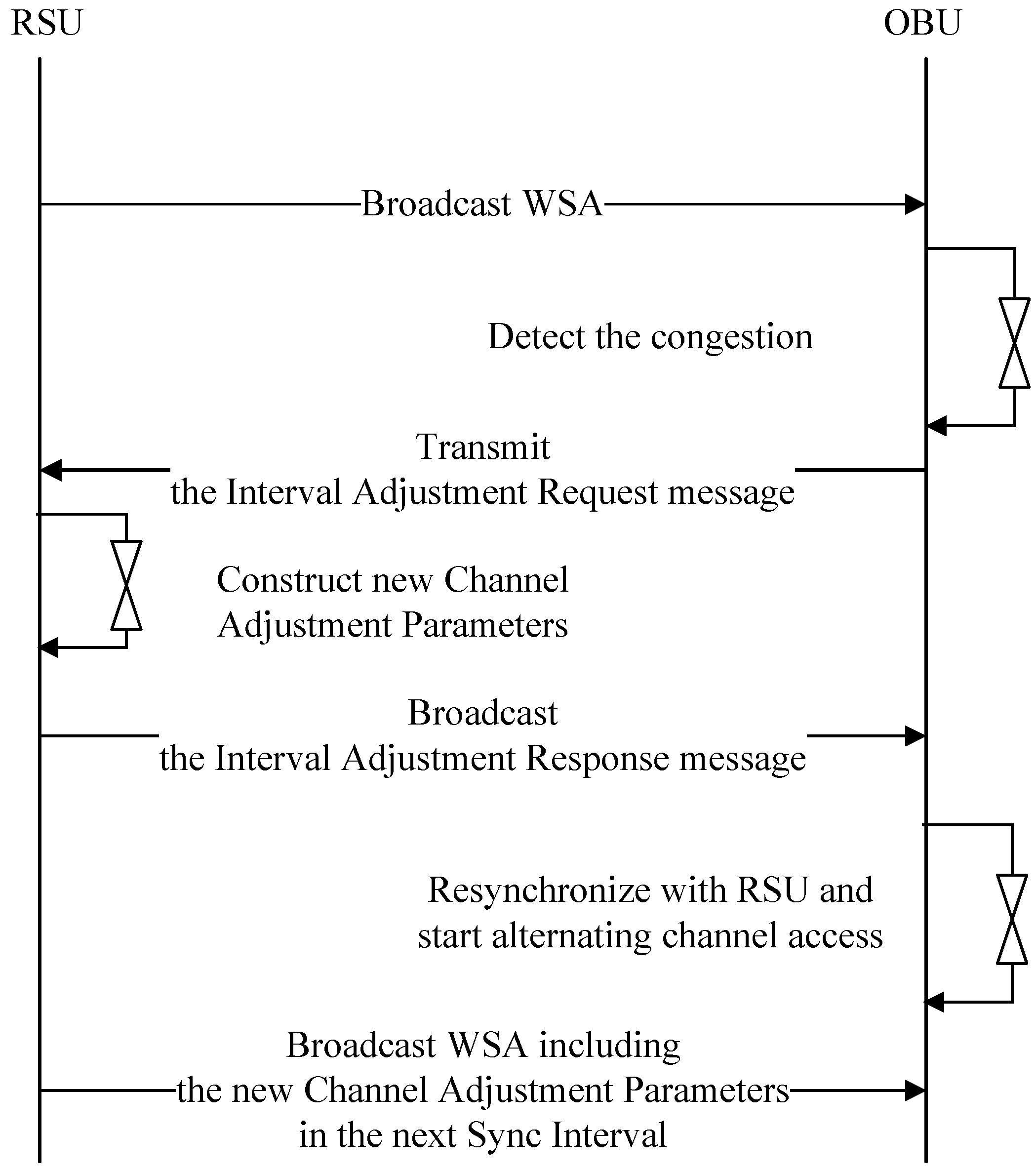
Figure 10 shows a flowchart depicting the process of changing the Sync Interval when an OBU detects congestion.
The RSU transmits an advertisement message to the OBU in the vehicle, which includes information about the services it offers. The OBU, upon detecting congestion, sends an Interval Adjustment Request message to the RSU requesting channel adjustment. Upon receiving the Interval Adjustment Request message, the RSU broadcasts an Interval Adjustment Response message containing new channel coordination parameters. The OBU, after receiving the new channel coordination parameters from the RSU, performs re-synchronization. Starting from the next Sync Interval, the RSU broadcasts the WSA containing the new channel coordination parameters.
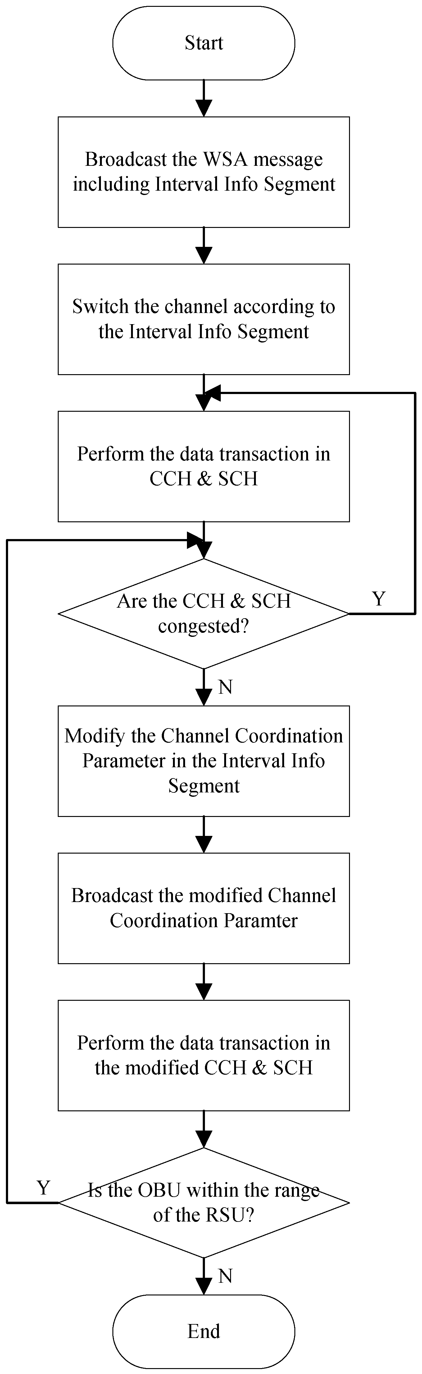
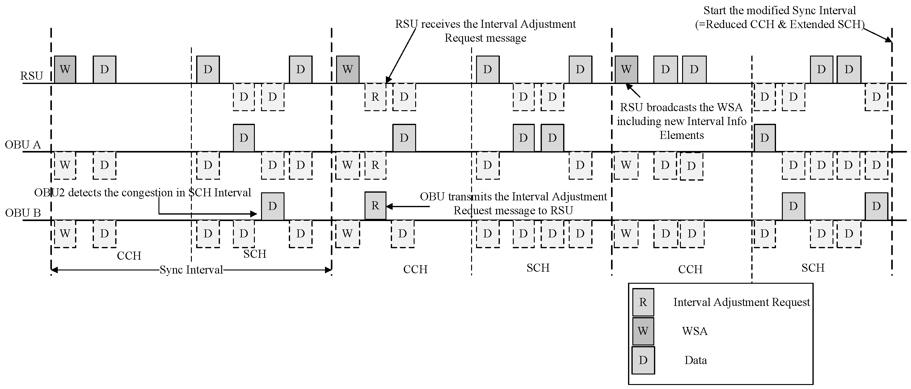
Figure 11 shows a flowchart depicting the process of Sync Interval adjustment by the OBU.
In
Figure 11, the OBU detects high congestion in the SCH. The OBU sends an Interval Adjustment Request message to the RSU in the CCH, requesting an increase in the SCHI. Upon receiving the Interval Adjustment Request message, the RSU modifies the Sync Interval and broadcasts an Interval Adjustment Response message containing the modified information. If the update time information of the modified channel coordination parameters is ‘0’, the OBUs that receive the Interval Adjustment Response message will apply the modified channel coordination parameters from the start of the next absolute time, decreasing the length of the CCH and increasing the length of the SCH for channel switching. The RSU will broadcast WSA containing the modified interval information elements from the next absolute time onwards.


