
Research on Tire Surface Damage Detection Method Based on Image Processing

Abstract
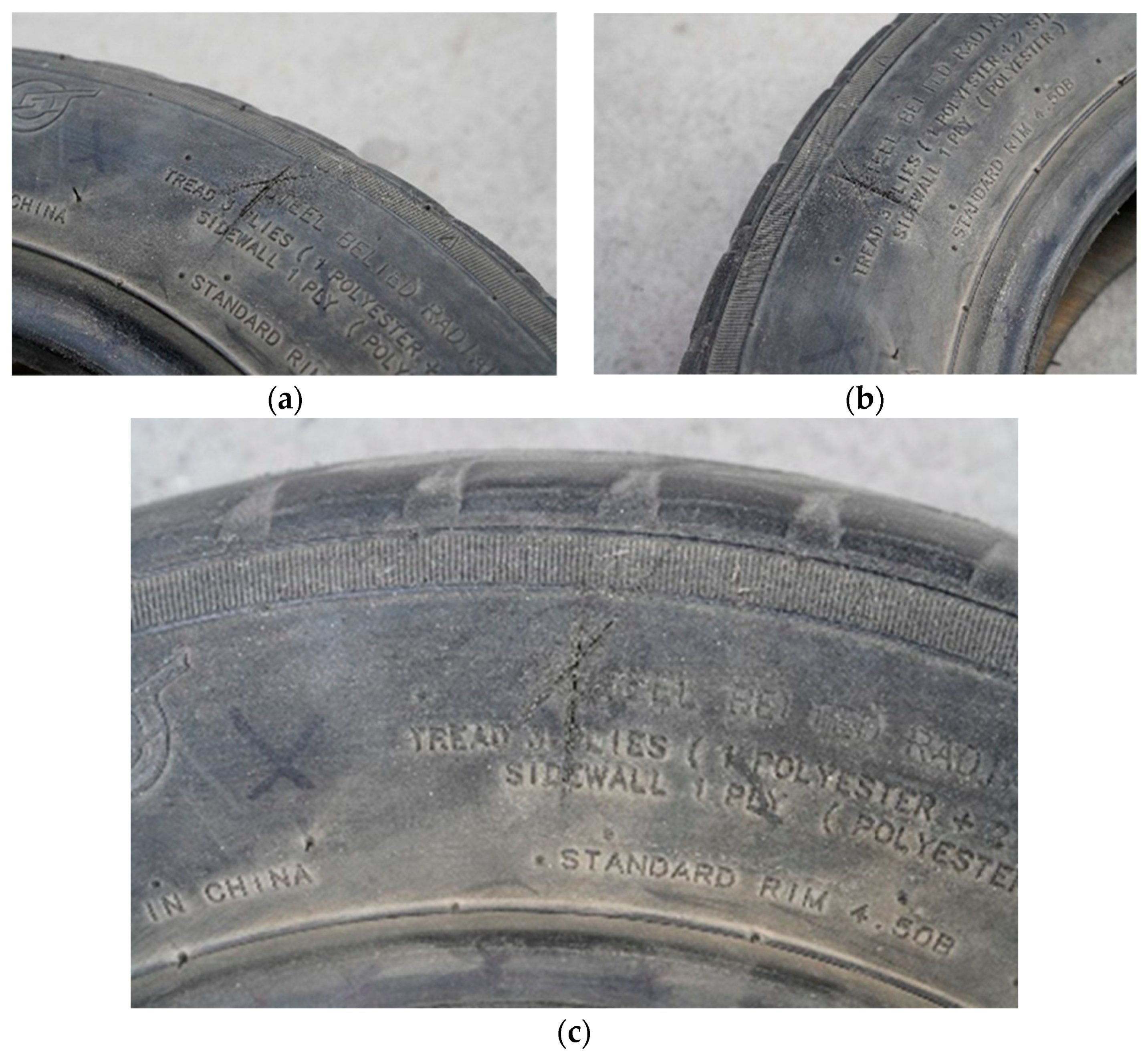
1. Introduction
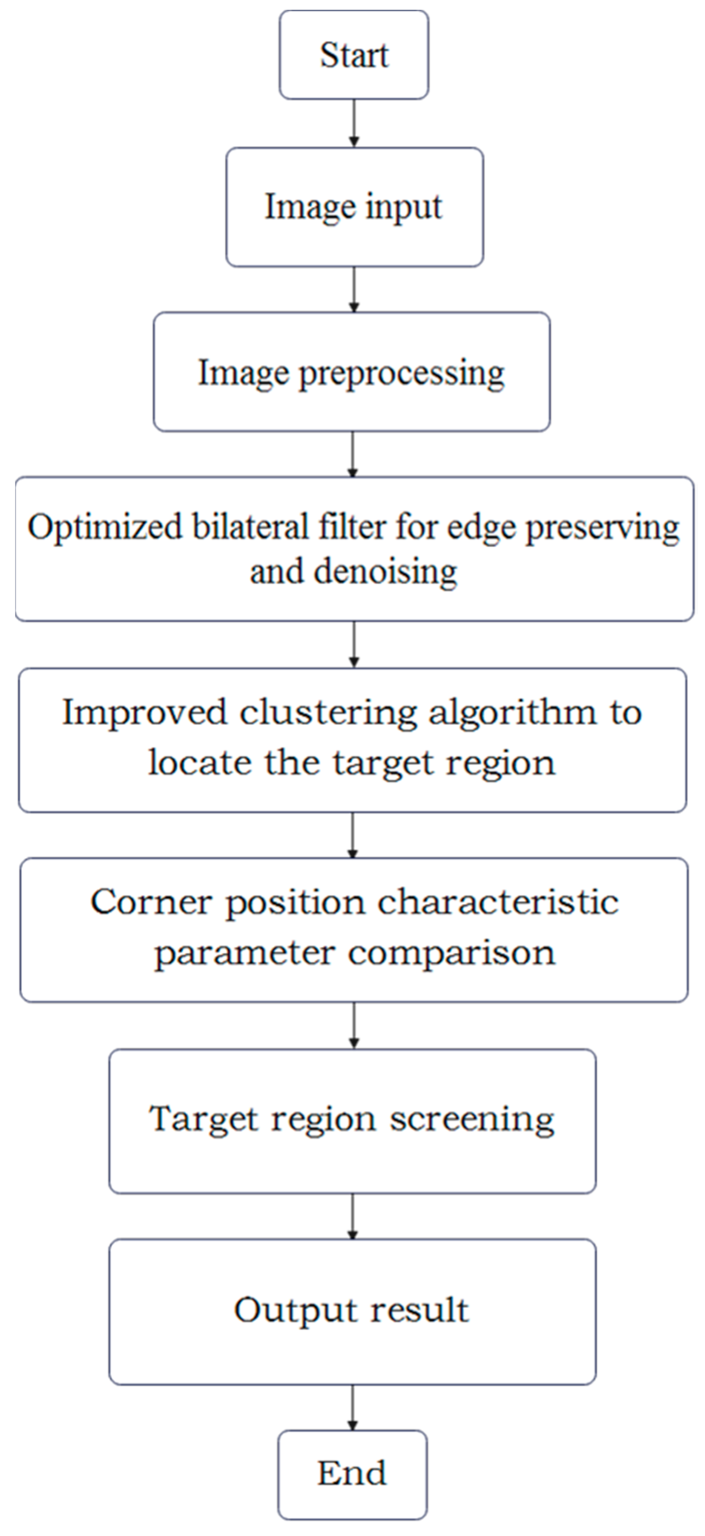
2. Technical Scheme Design
3. Image Segmentation Method Based on Improved K-Means Clustering Algorithm Validation
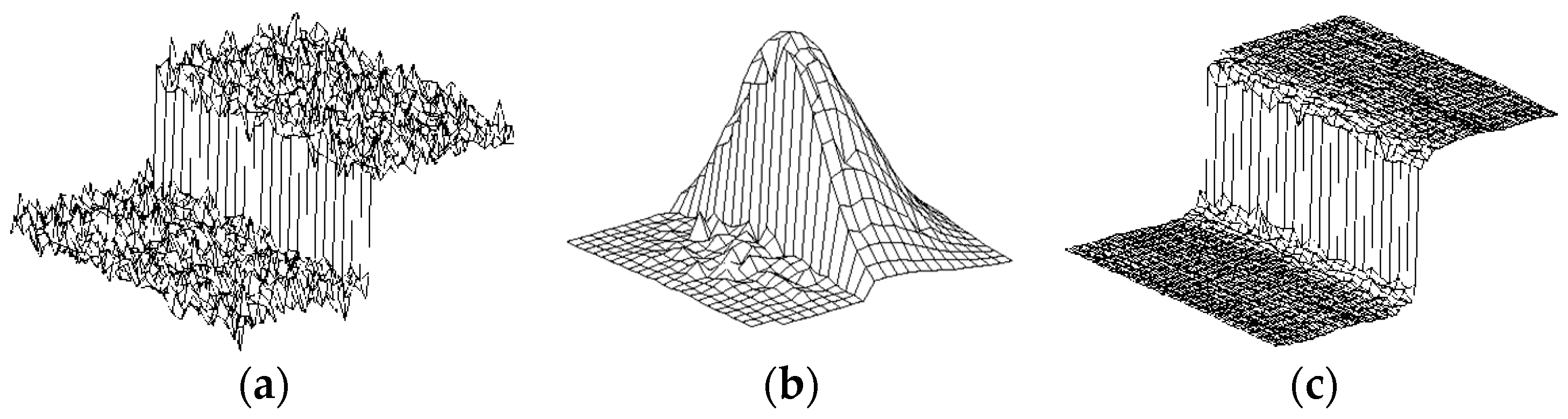
3.1. Image Preprocessing
- (1)
- Size_d is used as the diameter range of the pixel neighborhood in the noise reduction process.
- (2)
- Sigma_color is the σ value of the color space filter. The larger the value of this parameter, the wider colors in the pixel neighborhood will be mixed together to produce a larger semi-equal color region.
- (3)
- Sigma_space is the σ value of the coordinate space filter, and the larger the value, the more distant pixels will affect each other, so that a larger area of similar enough colors can obtain the same color.
3.2. Principle of Clustering Algorithm
3.3. Image Segmentation Method under Improved K-Means Clustering
- (1)
- First, the first cluster center is randomly selected, which is the initial cluster center.
- (2)
- Second, select the point far away from the first cluster center. The farther the distance, the higher the probability that it will be selected as the second cluster center. Thus, the target damage area with small gray value is different from the surrounding pixel with large gray value.
- (3)
- Third, repeat the above operations until K center points are finally selected.
- (4)
- Then, the cluster image is obtained, and the cluster including the target damage area is extracted to complete the image segmentation.
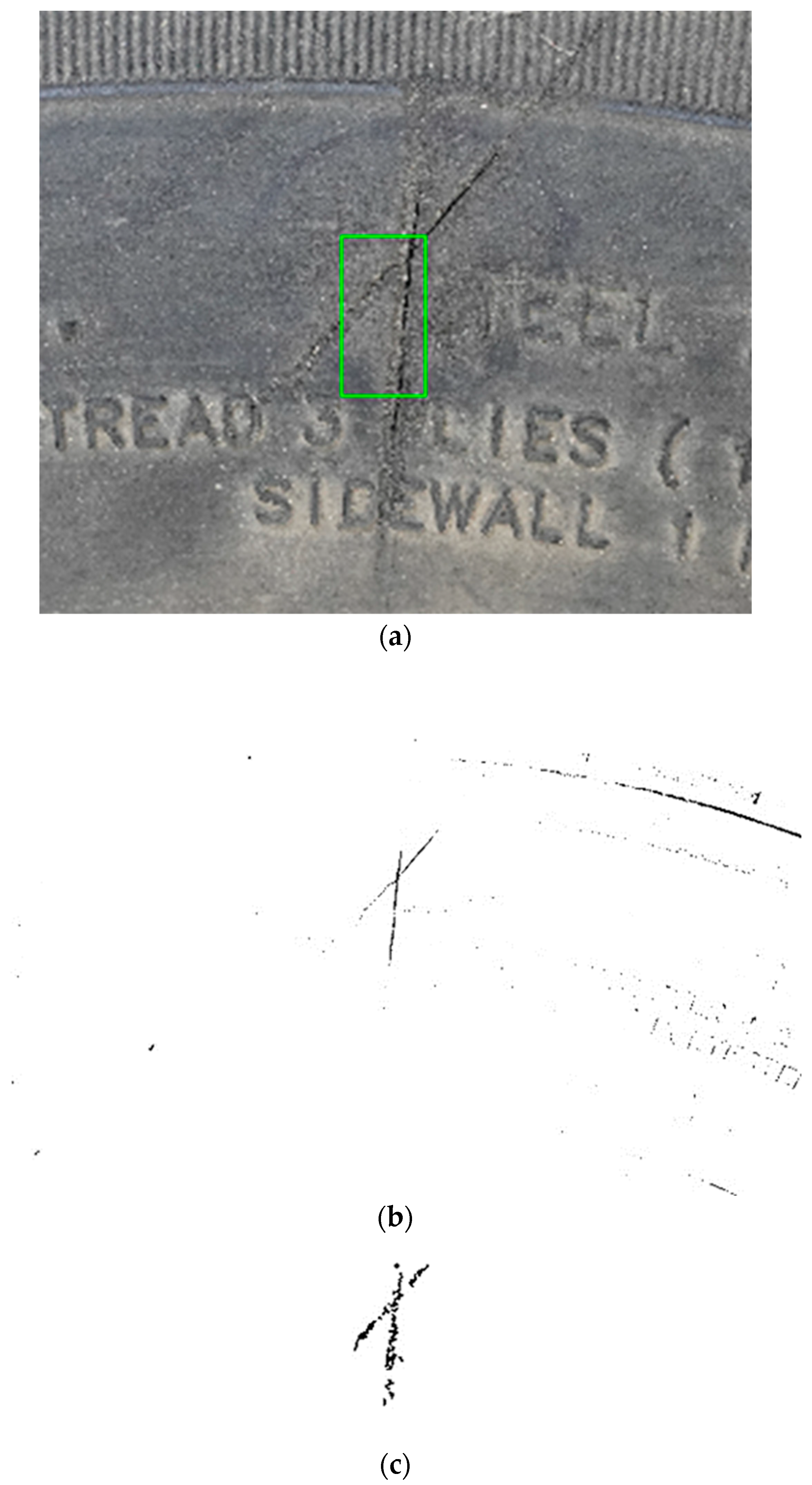
4. Matching Screening Method Based on Corner Detection
4.1. Corner Point
4.2. Matching Method Based on Histogram Correlation
5. Conclusions
- (1)
- This paper proposes a multi-scale bilateral filtering algorithm as a crucial component of image preprocessing. It effectively preserves edge information while achieving superior smoothing and denoising effects, thereby providing a solid foundation for subsequent image segmentation tasks. Based on the preprocessed images, an improved K-means clustering method is utilized to obtain an adaptive threshold for image segmentation. Consequently, a binary image representing the complete information of the damaged region is obtained. This approach offers high reliability and efficient performance.
- (2)
- Based on the Harris corner detection method and combined with the characteristics around the tire damage area, the “salt and pepper” corner points in the wear zone in the edge of the area are captured, and the binary image of corner distribution is obtained, which accurately reflects the damage area. This method has anti-interference and provides convenience for subsequent matching screening and matrix box marking.
- (3)
- In this paper, the region screening and matching based on histogram correlation method is used, the damage region can be accurately judged and matched by the maximum similarity, and the region matrix tool marker of the source image can be obtained by screening the edge corners. According to the test, the maximum value of the matching similarity can reach 1.00, and the remaining irrelevant information region can almost reach 0. It can meet the detection requirements of tire damage area.
- (4)
- This paper explores the automatic detection method of tire tread damage. Although preliminary research results have been obtained, there are still limitations in the use environment. First, the material of the tire. The research on tire material and composition is relatively single, and this method cannot meet all the materials of tires on the market. Secondly, due to the small scale of the dataset and the few types of damage areas, it is more difficult for individuals to collect experimental data due to the particularity of the scratch damage problem. In addition, this method is mainly for tires with more tread damage, and there are more detection blind areas.
Author Contributions
Funding
Institutional Review Board Statement
Informed Consent Statement
Data Availability Statement
Conflicts of Interest
References
- Li, Z. Study on the Impact of Damage Defects on the Safety of In-Service Tires. Master’s Thesis, Qingdao University of Science and Technology, Qingdao, China, 2015. [Google Scholar]
- Zhao, Y.; Min, S.; Li, D. Research on tire defect detection algorithm based on Principal Component Analysis. J. Shenyang Univ. Chem. Technol. 2022, 36, 187–192. [Google Scholar]
- Wang, C. Development of Tire Surface Defect Detection System. Master’s Thesis, University of Electronic Science and Technology of China, Chengdu, China, 2019. [Google Scholar]
- Sun, H.; Liu, S.; Leng, Y.; Liu, M.; Ding, H. Research and application of Tire Surface Defect detection System based on Machine vision. Ind. Control Comput. 2022, 35, 29–30+34. [Google Scholar]
- Zheng, B.; Luo, S.; Jiang, Y. Research on tire tread defect detection method based on RGB image processing. Manuf. Autom. 2023, 45, 35–38+49. [Google Scholar]
- Gu, H.; Chen, S. A tire defect detection system based on Deep Learning. Comput. Digit. Eng. 2022, 50, 1463–1467. (In Chinese) [Google Scholar]
- Sun, Y. Research on Non-Destructive Detection of Tire Defects Based on Semantic Segmentation. Master’s Thesis, Qingdao University of Science and Technology, Qingdao, China, 2023. [Google Scholar]
- Zhao, M. Research on Tire Defect Detection Method Based on Object Detection. Master’s Thesis, Qingdao University of Science and Technology, Qingdao, China, 2023. [Google Scholar]
- Yang, S. Research on Intelligent Nondestructive Testing of Tire Defects Based on Deep Learning. Master’s Thesis, Qingdao University of Science and Technology, Qingdao, China, 2023. [Google Scholar]
- Lin, G. Research review of image segmentation based on clustering. Comput. Knowl. Technol. 2022, 18, 17–18+24. [Google Scholar]
- Zeng, R. Research on Improvement and Application of K-Means Clustering Algorithm. Master’s Thesis, China West Normal University, Nanchong, China, 2022. [Google Scholar]
- Guo, W. K-means clustering algorithm based on optimization of initial clustering center. Sci. Technol. Wind. 2022, 4, 63–65. [Google Scholar]
- Cao, D.; Tang, J.; Chen, X. An adaptive clustering algorithm for optimizing initial clustering center. J. Softw. Guide 2020, 19, 28–31. [Google Scholar]
- Guo, Y.; Zhang, X.; Liu, L.; Ding, L.; Niu, X. K-means clustering algorithm for optimizing initial clustering center. Comput. Eng. Appl. 2020, 56, 172–178. (In Chinese) [Google Scholar]
- Long, J.; Chen, D. Image segmentation algorithm based on multi-scale kernel fuzzy clustering. J. Chongqing Univ. Technol. (Nat. Sci.) 2023, 37, 166–178. (In Chinese) [Google Scholar]
- Shang, S.; Cao, J.; Wang, M.; Zheng, X.; Gao, H. Research on Corner Detection Algorithm in Machine Vision. Comput. Meas. Control 2024, 32, 1–14. (In Chinese) [Google Scholar]
- Shang, M.; Wang, K.D. Image registration algorithm based on multi-scale Harris corner detection. Electro-Opt. Control 2024, 31, 28–32. (In Chinese) [Google Scholar]
- Yao, Y.; Wang, W. Application research of Harris Corner Detection Algorithm. Intell. Comput. Appl. 2022, 12, 148–151. [Google Scholar]
- Jiang, Y.; Xie, R.; Li, Y.; He, Y.; Chen, J. Research on corner detection algorithm based on image edge contour. Electron. Des. Eng. 2022, 30, 185–188. [Google Scholar]


| Picture Number | Max Similarity Value | Output |
|---|---|---|
| Pic. 3 | 0.9981 | True |
| Pic. 11 | 0.9071 | True |
| Pic. 13 | 0.6098 | False |
| Pic. 21 | 0.9030 | True |
| Pic. 27 | 1.0000 | True |
| Pic. 30 | 1.0000 | True |
Disclaimer/Publisher’s Note: The statements, opinions and data contained in all publications are solely those of the individual author(s) and contributor(s) and not of MDPI and/or the editor(s). MDPI and/or the editor(s) disclaim responsibility for any injury to people or property resulting from any ideas, methods, instructions or products referred to in the content. |
© 2024 by the authors. Licensee MDPI, Basel, Switzerland. This article is an open access article distributed under the terms and conditions of the Creative Commons Attribution (CC BY) license (https://creativecommons.org/licenses/by/4.0/).
Share and Cite
Chen, J.; Li, A.; Zheng, F.; Chen, S.; He, W.; Zhang, G. Research on Tire Surface Damage Detection Method Based on Image Processing. Sensors 2024, 24, 2778. https://doi.org/10.3390/s24092778
Chen J, Li A, Zheng F, Chen S, He W, Zhang G. Research on Tire Surface Damage Detection Method Based on Image Processing. Sensors. 2024; 24(9):2778. https://doi.org/10.3390/s24092778
Chicago/Turabian StyleChen, Jiaqi, Aijuan Li, Fei Zheng, Shanshan Chen, Weikai He, and Guangping Zhang. 2024. "Research on Tire Surface Damage Detection Method Based on Image Processing" Sensors 24, no. 9: 2778. https://doi.org/10.3390/s24092778
APA StyleChen, J., Li, A., Zheng, F., Chen, S., He, W., & Zhang, G. (2024). Research on Tire Surface Damage Detection Method Based on Image Processing. Sensors, 24(9), 2778. https://doi.org/10.3390/s24092778