
Three-Chamber Actuated Humanoid Joint-Inspired Soft Gripper: Design, Modeling, and Experimental Validation


Abstract
:1. Introduction
2. Design and Fabrication
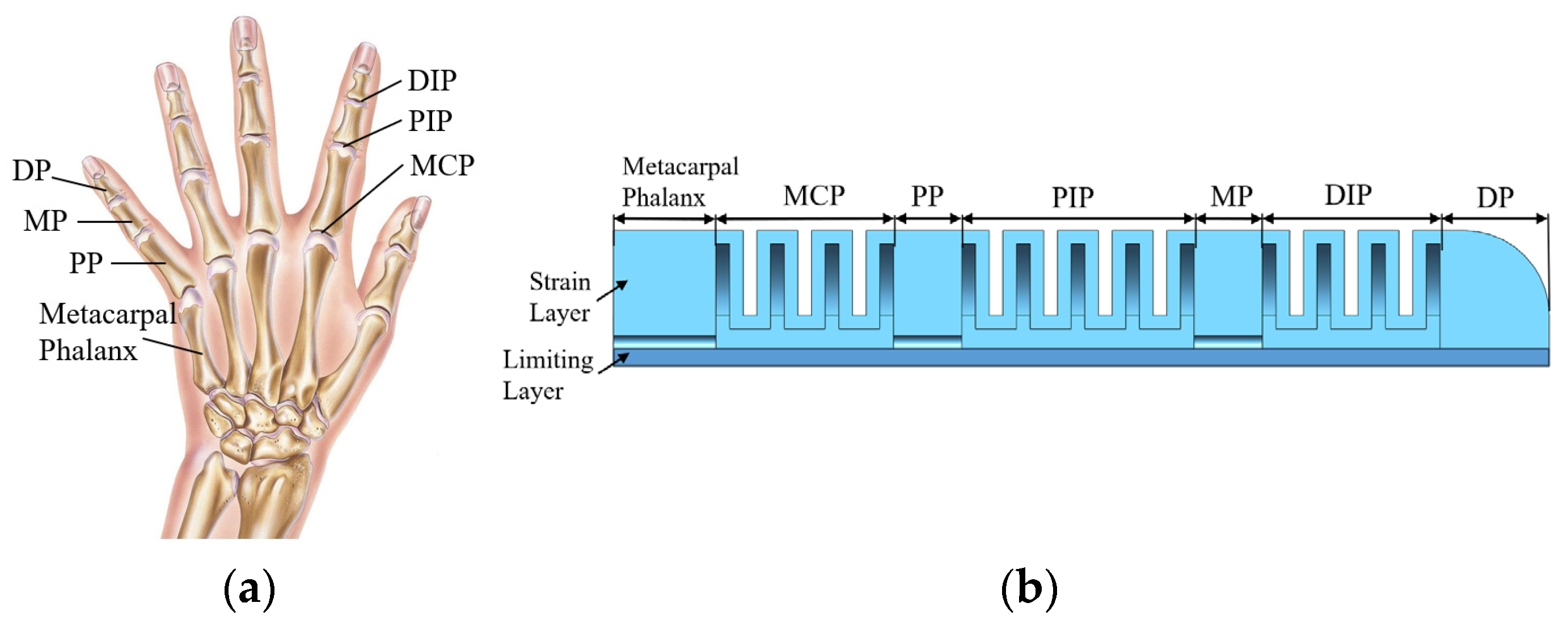
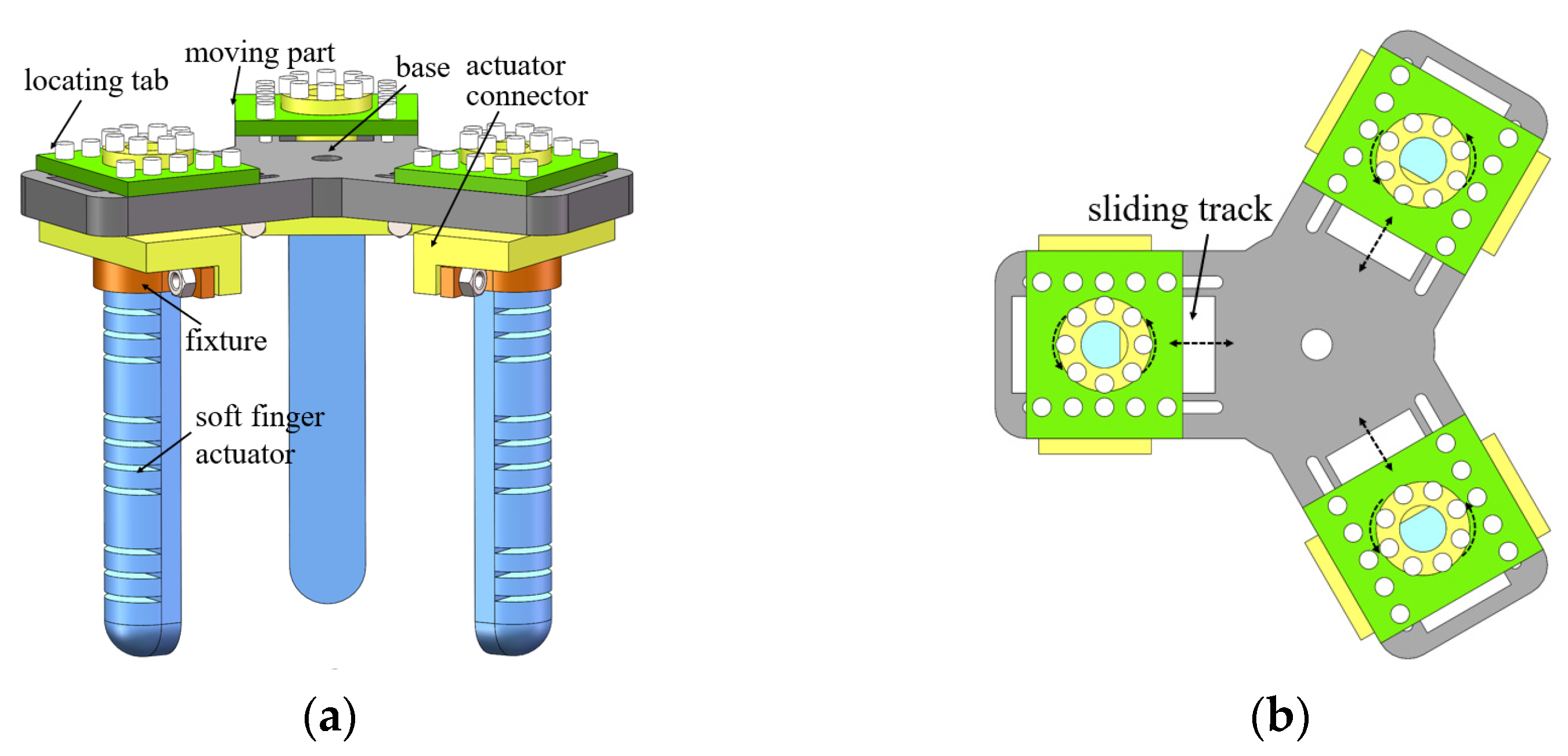
2.1. Structural Design
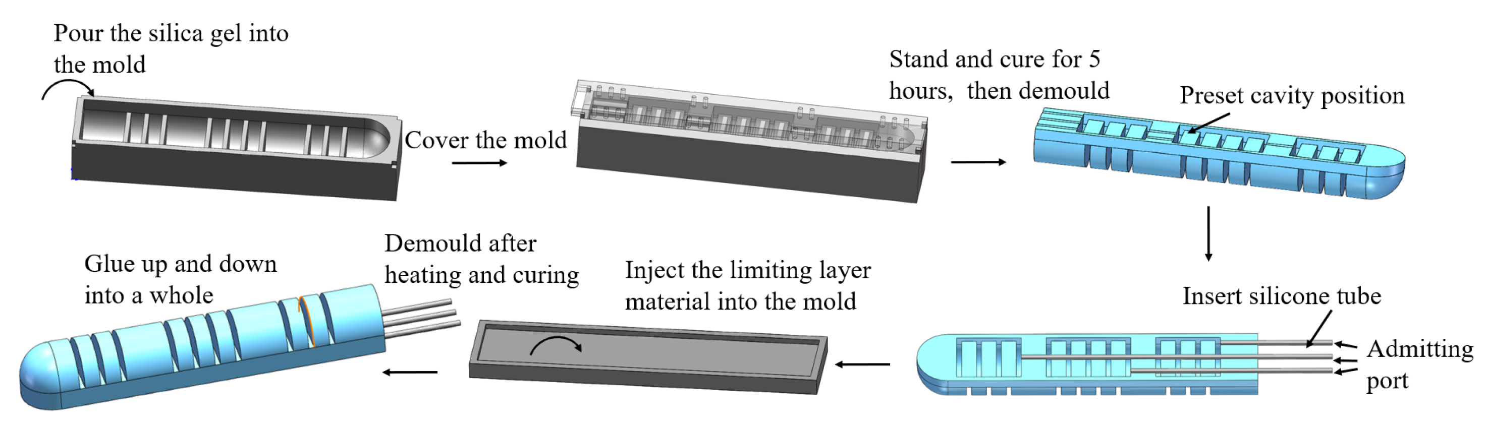
2.2. Fabrication
3. Mathematical Modeling and Kinematics Analysis
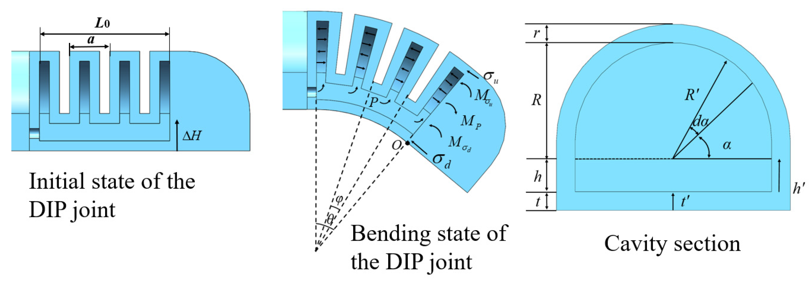
3.1. Mathematical Model of Joint Bending
3.2. Kinematics Analysis of Soft Finger
3.2.1. Kinematics Analysis
3.2.2. Working Space Analysis
4. Simulation Analysis and Performance Test
4.1. Simulation Analysis
- (1)
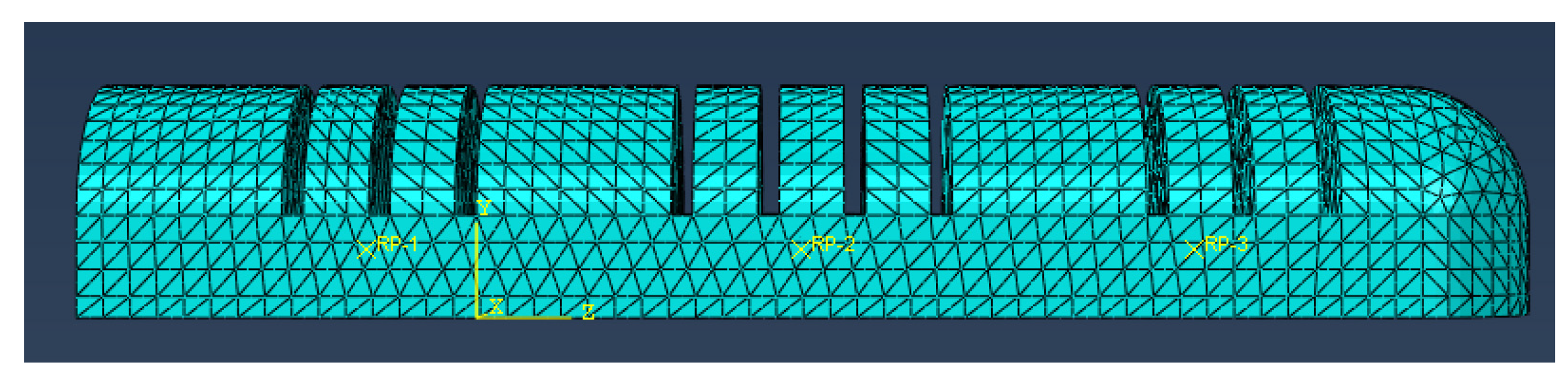
- The soft finger actuator was designed using SolidWorks 2018 and subsequently imported into ABAQUS to create the finite element simulation analysis model. In the grid attribute module, to accommodate the complex structure of the actuator and enhance the convergence of the simulation model, all actuators were simplified into a quadratic hybrid entity unit (C3D10H), as illustrated in Figure 11.
- (2)
- The entire soft finger actuator is classified as a superelastomer. The strain layer of the soft finger was composed of Dragon Skin 20 silica gel, with material coefficients C10 and C20 under the Yeoh model being 0.11 and 0.02, respectively. Specific tensile test data can be referenced in [33]. The limiting layer was constructed from PDMS/PTFE with a mass ratio of 8:1, and the material parameter under the Neo-Hookean model was 0.962 [33].
- (3)
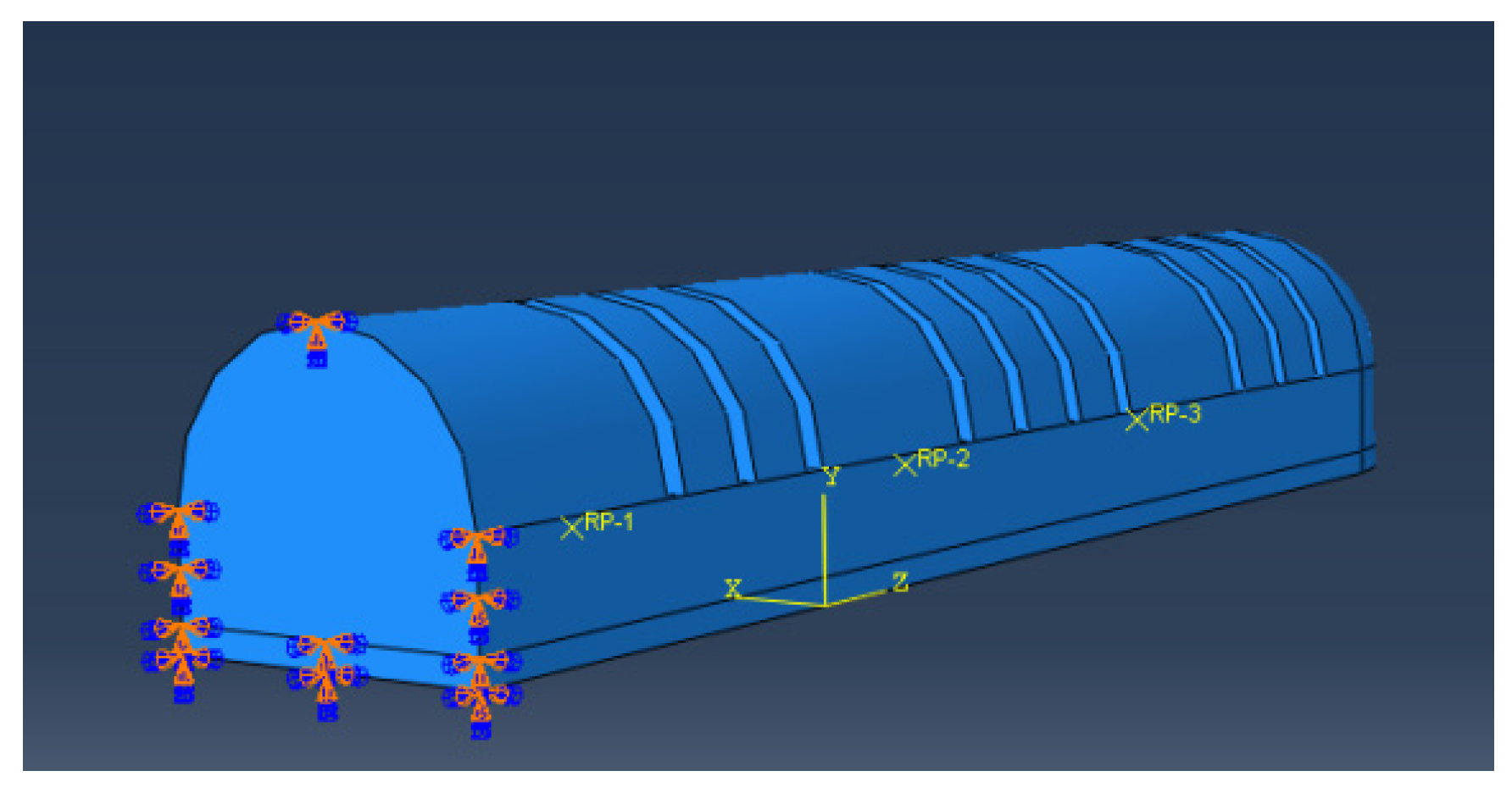
- Constraints were established at the location of the inflation port of the actuator to ensure that it remained unaffected during the bending deformation process. The fingertip served as the free end, allowing for an accurate representation of the inflation deformation process of the humanoid finger driver, as illustrated in Figure 12.
- (4)
- The properties of the fluid chamber were set and the pressure of the fluid chamber on the inner walls of the three bending joints of the actuator was established. During the process of applying air pressure to the chamber of the soft finger actuator, the outer wall of the joint section of the chamber expands and deforms, causing the adjacent chamber walls to come into contact and compress against each other. Therefore, it was essential to implement self-contact on the surfaces that may interact to prevent the chamber walls from penetrating one another, which could lead to non-convergence of the simulation. Additionally, the mechanical properties of the self-contact were configured to exhibit frictionless and normal hard contact behavior.
4.1.1. Simulation Analysis of Phalanx Length
4.1.2. Simulation Analysis of Soft Finger Bending
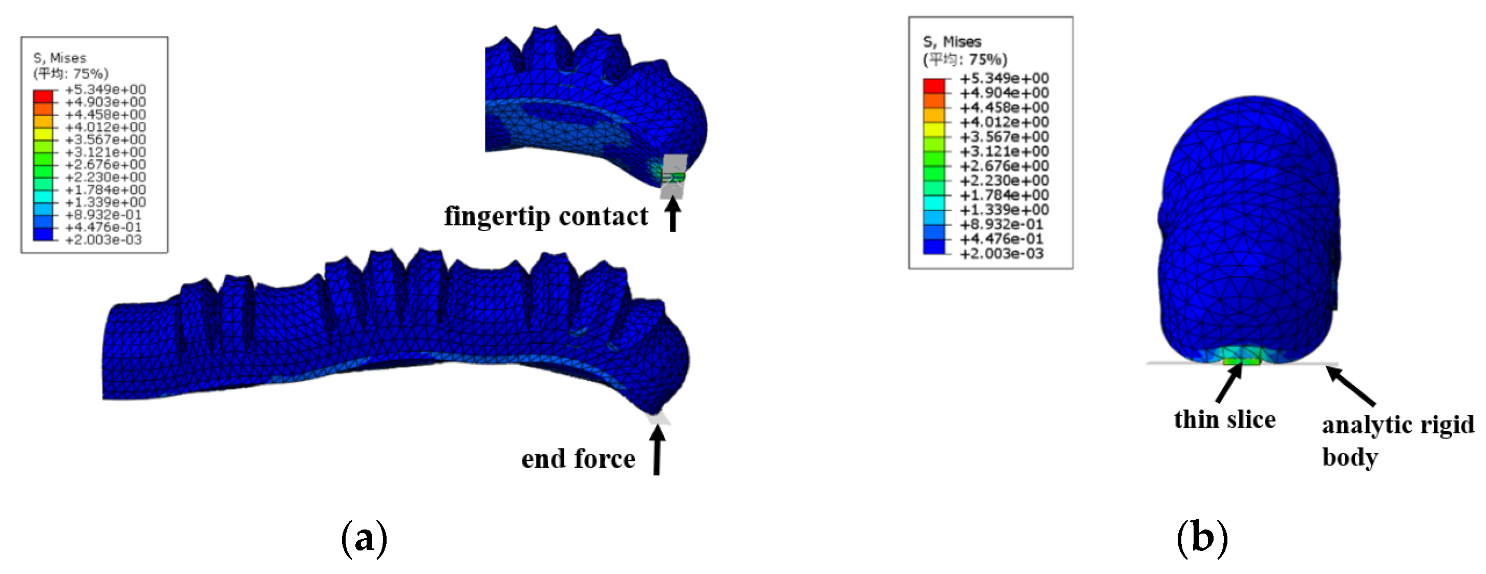
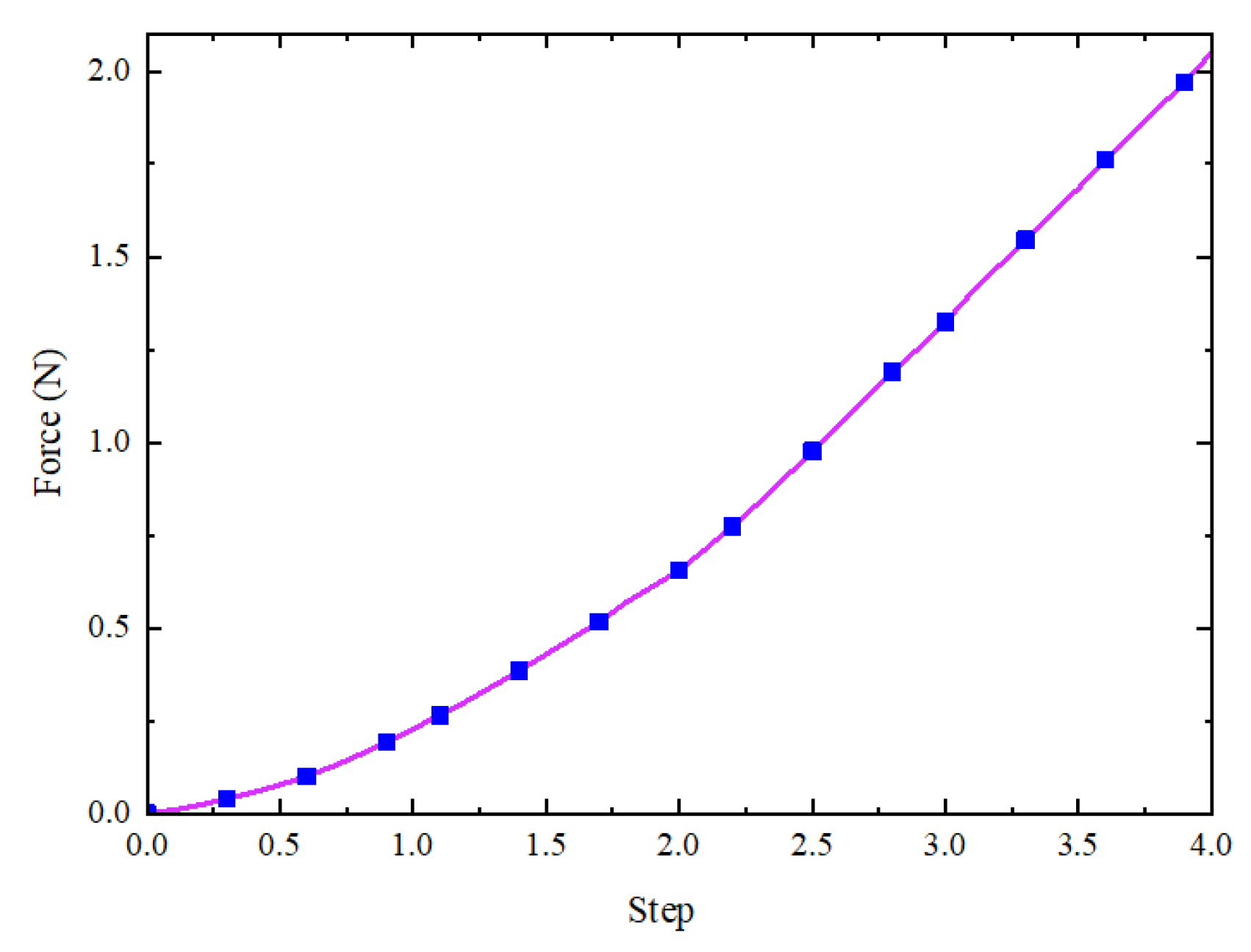
4.1.3. Simulation Analysis of Terminal Force
4.2. Performance Test of Humanoid Joint-Inspired Soft Gripper
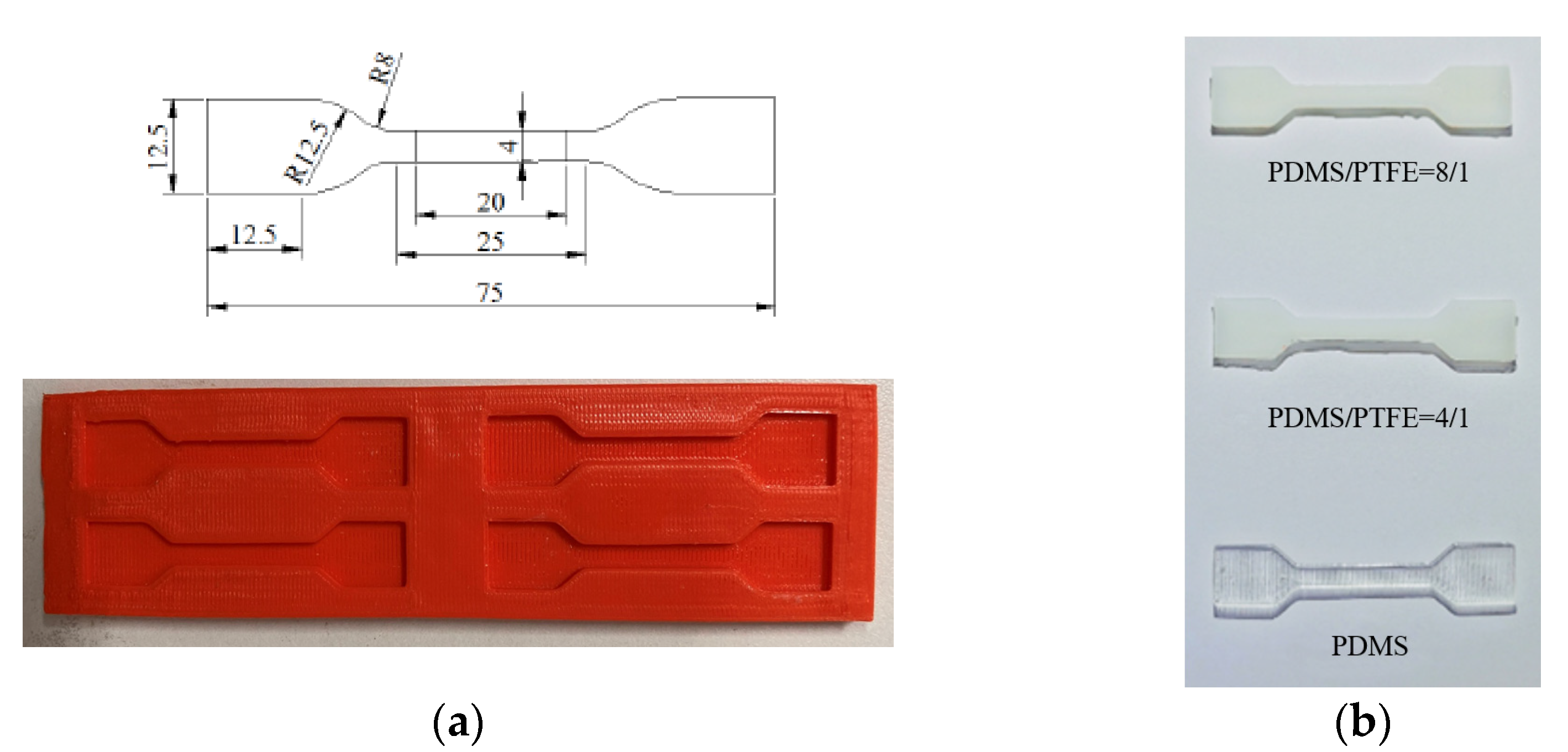
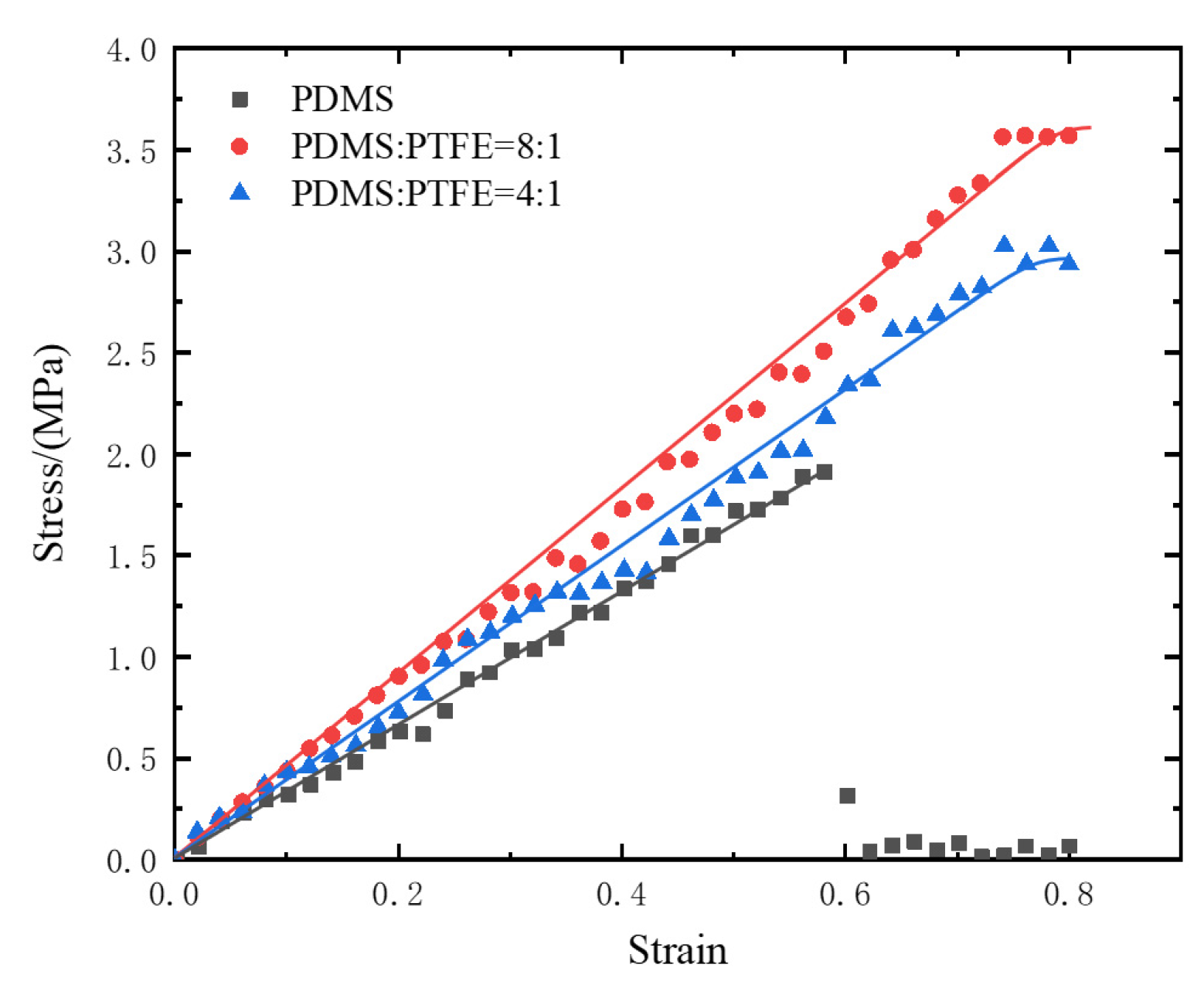
4.2.1. Uniaxial Tensile Test of PDMS/PTFE Composites
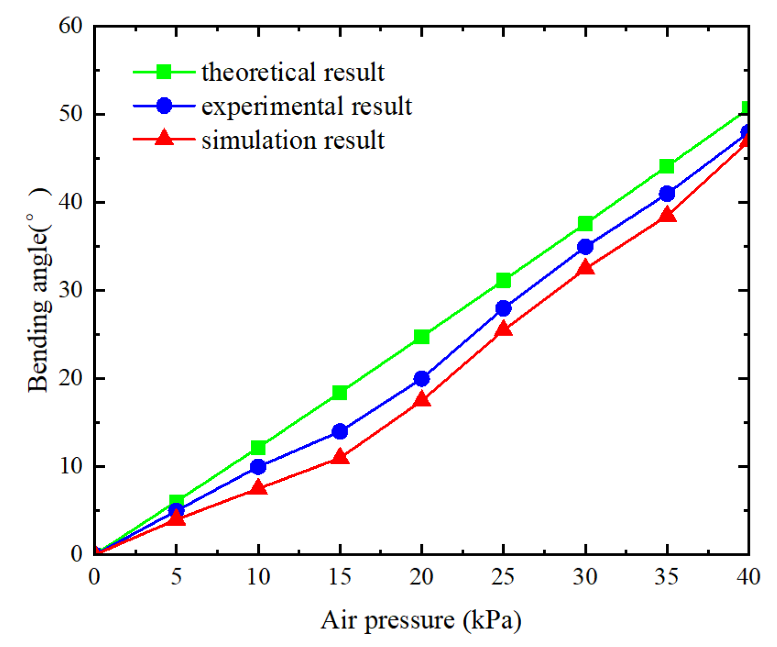
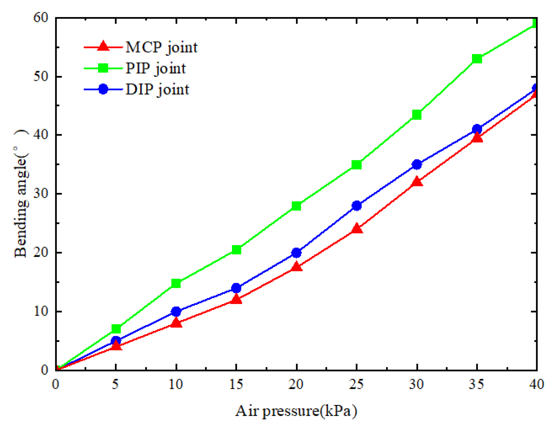
4.2.2. Flexural Performance Test of Soft Finger
4.2.3. Terminal Force Test of Soft Finger
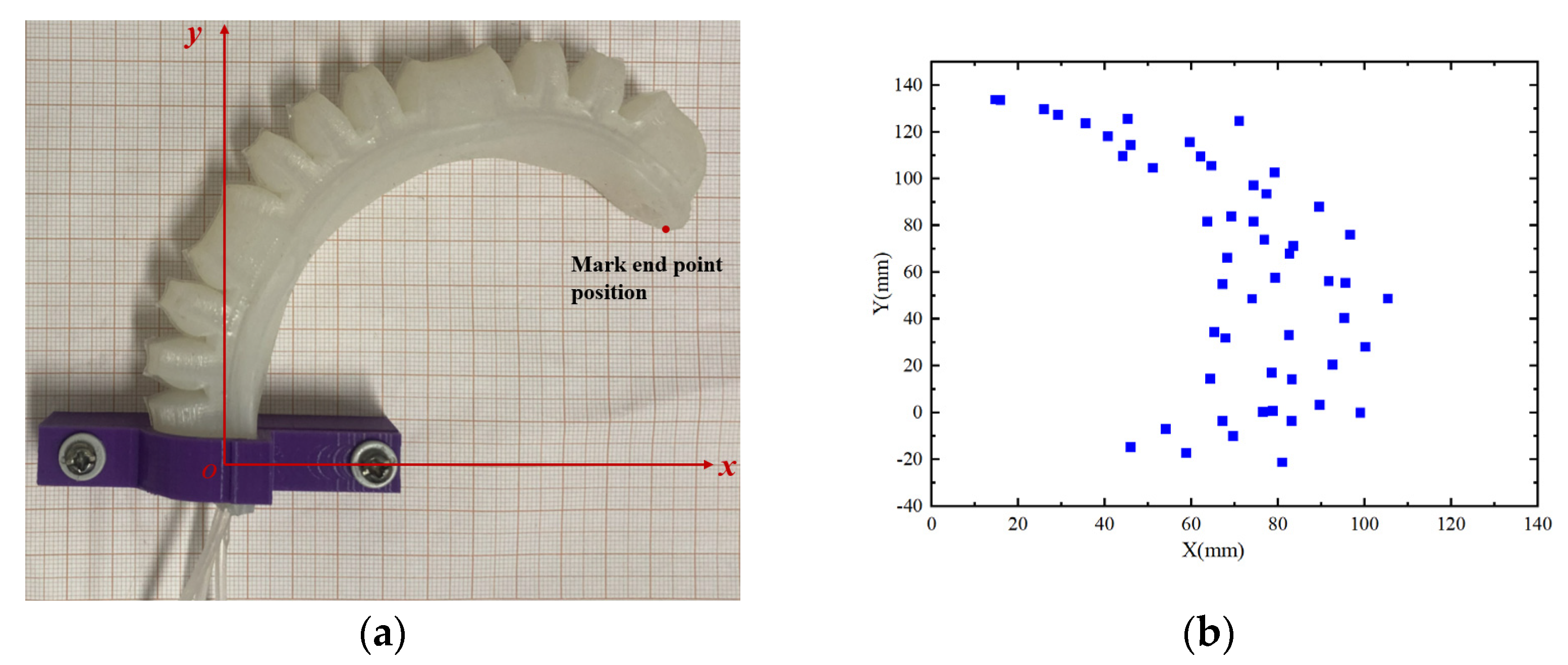
4.2.4. Trajectory Test of Endpoint of Soft Finger
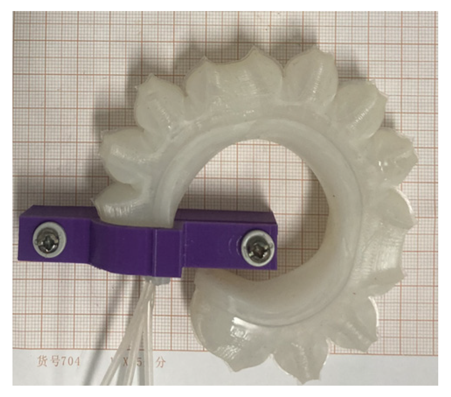
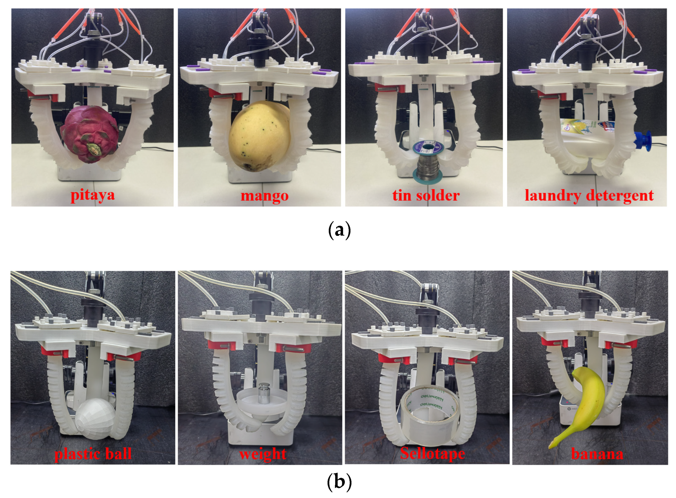
4.2.5. Grasping Performance Test of Soft Gripper
5. Conclusions
- This paper presents a humanoid joint-inspired soft gripper actuated by a three-chamber system. Each soft finger is independently driven by separate air chambers, with a constraint layer composed of a PDMS base, PDMS curing agent, and PTFE in a mass ratio of 5:1:0.75. Experimental results demonstrate that a single soft finger can generate a maximum fingertip force of 2.21 N, while the three-finger assembly can grasp objects weighing up to 0.92 kg, including mangoes, detergent bottles, and soldering wire. These results underscore the design’s excellent adaptability and stable grasping capability across various shapes and sizes.
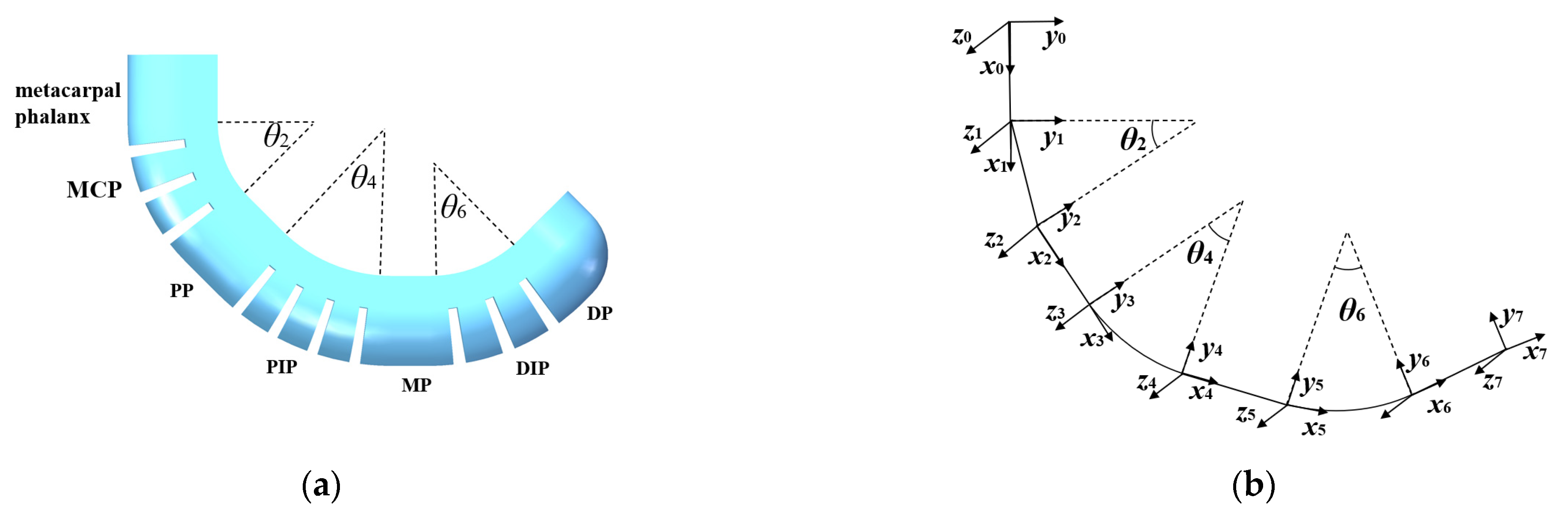
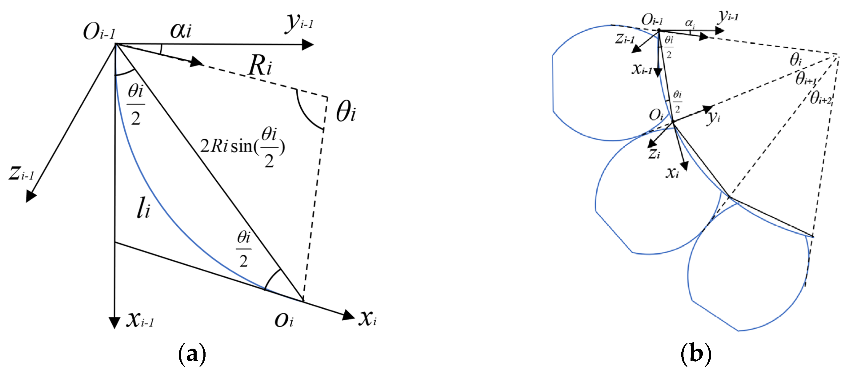
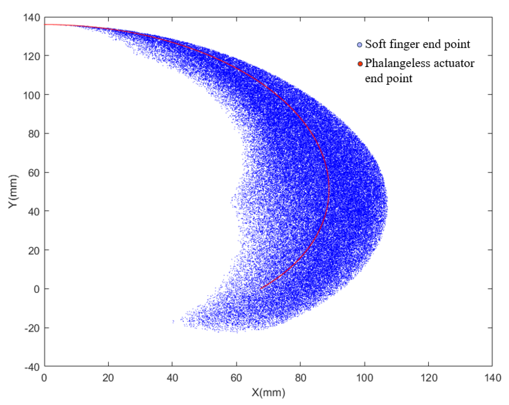
- Based on the constant curvature assumption and moment balance principle, this study employs the Yeoh and Neo-Hookean models to establish a nonlinear mathematical model for the distal joint of the soft finger, with experimental validation confirming its accuracy. Additionally, kinematic analysis is conducted using the D–H parameter method to calculate the fingertip position and orientation. A comparison with a phalangeless actuator reveals that the proposed design offers a larger workspace and greater flexibility.
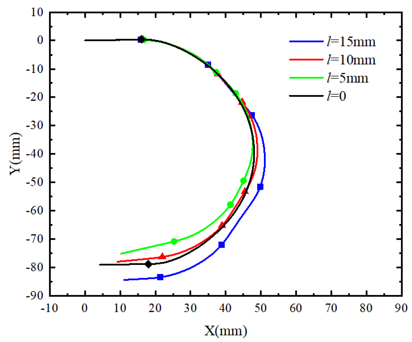
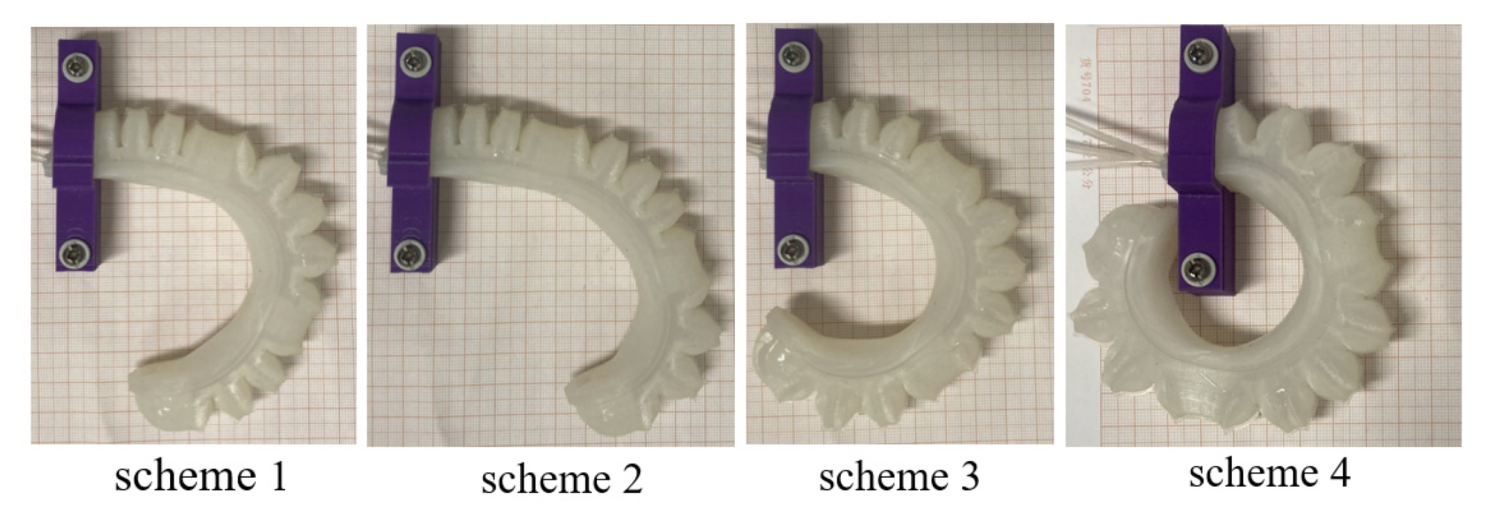
- In the ABAQUS simulation analysis, the effects of different pressure combinations on the grasping ability of the soft fingers are explored, along with comparisons for phalange lengths of 5 mm, 10 mm, and 15 mm. Results indicate that the phalangeless model exhibits poor bending capability, while a phalange length of 10 mm provides the best grasping performance and structural stability while maintaining a low weight. Furthermore, within the actuation pressure range of 0–40 kPa, the simulated maximum fingertip force reaches 2.05 N, with a maximum deviation of approximately 7% from the experimental results, thereby verifying the reliability of the proposed design.
Author Contributions
Funding
Institutional Review Board Statement
Informed Consent Statement
Data Availability Statement
Conflicts of Interest
References
- Lin, J.; Hu, Q.; Xia, J.; Zhao, L.; Du, X.; Li, S.; Chen, Y.; Wang, X. Non-destructive fruit firmness evaluation using a soft gripper and vision-based tactile sensing. Comput. Electron. Agric. 2023, 214, 108256. [Google Scholar] [CrossRef]
- Gao, M.; Sun, Y.; Zhang, J.; Ying, Z. A novel pneumatic gripper driven by combination of soft fingers and bellows actuator for flexible grasping. Sens. Actuators A Phys. 2023, 355, 114335. [Google Scholar]
- Mosadegh, B.; Polygerinos, P.; Keplinger, C.; Wennstedt, S.; Shepherd, R.F.; Gupta, U.; Shim, J.; Bertoldi, K.; Walsh, C.J.; Whitesides, G.M. Soft robotics: Pneumatic networks for soft robotics that actuate rapidly. Adv. Funct. Mater. 2014, 24, 2163–2170. [Google Scholar] [CrossRef]
- Webster, R.J.; Jones, B.A. Design and kinematic modeling of constant curvature continuum robots. Int. J. Robot. Res. 2010, 29, 1661–1683. [Google Scholar] [CrossRef]
- Zhang, B.; Xie, Y.; Zhou, J.; Wang, K.; Zhang, Z. State-of-the-art robotic grippers, grasping and control strategies, as well as their applications in agricultural robots: A review. Comput. Electron. Agric. 2020, 177, 105694. [Google Scholar] [CrossRef]
- Elfferich, J.F.; Dodou, D.; Santina, C.D. Soft robotic grippers for crop handling or harvesting: A review. IEEE Access 2022, 10, 75428–75443. [Google Scholar] [CrossRef]
- Gong, W.; Lian, J.; Zhu, Y. Capacitive flexible haptic sensor based on micro-cylindrical structure dielectric layer and its decoupling study. Measurement 2023, 223, 113785. [Google Scholar] [CrossRef]
- In, H.; Kang, B.B.; Sin, M.; Cho, K.-J. Exo-Glove: A wearable robot for the hand with a soft tendon routing system. IEEE Robot. Autom. Mag. 2015, 22, 97–105. [Google Scholar] [CrossRef]
- Dinakaran, V.P.; Balasubramaniyan, M.P.; Muthusamy, S.; Panchal, H. Performa of SCARA based intelligent 3 axis robotic soft gripper for enhanced material handling. Adv. Eng. Softw. 2023, 176, 103366. [Google Scholar] [CrossRef]
- Goh, G.D.; Goh, G.L.; Lyu, Z.; Ariffin, M.Z.; Yeong, W.Y.; Lum, G.Z.; Campolo, D.; Han, B.S.; Wong, H.Y.A. 3D Printing of robotic soft grippers: Toward smart actuation and sensing. Adv. Mater. Technol. 2022, 7, 2101672. [Google Scholar] [CrossRef]
- Xie, M.; Zhu, M.; Yang, Z.; Okada, S.; Kawamura, S. Flexible self-powered multifunctional sensor for stiffness-tunable soft robotic gripper by multimaterial 3D printing. Nano Energy 2021, 79, 105438. [Google Scholar] [CrossRef]
- Martinez, R.V.; Glavan, A.C.; Keplinger, C.; Oyetibo, A.I.; Whitesides, G.M. Soft actuators and robots that are resistant to mechanical damage. Adv. Funct. Mater. 2014, 24, 3003–3010. [Google Scholar] [CrossRef]
- Zhang, Y.F.; Zhang, N.; Hingorani, H.; Ding, N.; Wang, D.; Yuan, C.; Zhang, B.; Gu, G.; Ge, Q. Fast-response, stiffness-tunable soft actuator by hybrid multimaterial 3D printing. Adv. Funct. Mater. 2019, 29, 1806698. [Google Scholar] [CrossRef]
- Goh, G.L.; Yeong, W.Y.; Altherr, J.; Tan, J.; Campolo, D. 3D printing of soft sensors for soft gripper applications. Mater. Today Proc. 2022, 70, 224–229. [Google Scholar] [CrossRef]
- Ye, Y.; Cheng, P.; Yan, B.; Lu, Y.; Wu, C. Design of a novel soft pneumatic gripper with variable gripping size and mode. J. Intell. Robot. Syst. 2022, 106, 5. [Google Scholar] [CrossRef]
- Jo, Y.; Park, Y.; Son, H.I. A suction cup-based soft robotic gripper for cucumber farversting: Design and validation. Biosyst. Eng. 2024, 238, 143–156. [Google Scholar] [CrossRef]
- Lee, K.; Cha, Y. Quasi-static analysis of an electrohydraulic actuator for a soft gripper. Sens. Actuators A Phys. 2023, 352, 114214. [Google Scholar] [CrossRef]
- Du, H.; Xu, X.; Shao, R.; Xiong, W.; Wang, H. Design and verification of artificial muscle flexible manipulator with high grasping ability. J. Mech. Eng. 2023, 59, 17. (In Chinese) [Google Scholar]
- Wei, Y.; Chen, Y.; Ren, T.; Chen, Q.; Yan, C.; Yang, Y.; Li, Y. A Novel, Variable Stiffness Robotic Gripper Based on Integrated Soft Actuating and Particle Jamming. Soft Robot. 2016, 3, 134–143. [Google Scholar] [CrossRef]
- Zhao, P.; Xiong, C.; Gao, Z.; Liu, X.; Zeng, Y. Design and experiment investigation on soft grippers with modular variable stiffness structure. Micromachines 2024, 15, 88. [Google Scholar] [CrossRef]
- Zhang, N.; Ren, J.; Dong, Y.; Yang, X.; Bian, R.; Li, J.; Gu, G.; Zhu, X. Soft robotic hand with tactile palm-finger coordination. Nat. Commun. 2025, 16, 2395. [Google Scholar] [CrossRef] [PubMed]
- Han, F.; Zhang, D.; Zhao, X.; Dou, J.; Sun, Y. Design of bionic soft hand with compound cavity for underwater grasping operation. Robot 2023, 45, 2. (In Chinese) [Google Scholar]
- Xie, Z.; Domel, A.G.; An, N.; Green, C.; Gong, Z.; Wang, T.; Knubben, E.M.; Weaver, J.C.; Bertoldi, K.; Wen, L. Octopus arm-inspired tapered soft actuators with suckers for improved grasping. Soft Robot. 2020, 7, 639–648. [Google Scholar] [CrossRef]
- Hao, T.; Xiao, H.; Liu, S.; Zhang, C.; Ma, H. Multijointed pneumatic soft hand with flexible thenar. Soft Robot. 2021, 9, 4. [Google Scholar] [CrossRef]
- Liu, Y.; Xiao, H.; Hao, T.; Pang, D.; Wang, F.; Liu, S. Dexterous all-soft hand (DASH) with active palm: Multi-functional soft hand beyond grasping. Smart Mater. Struct. 2023, 32, 125012. [Google Scholar] [CrossRef]
- Hashemi, S.; Bentivegna, D.; Durfee, W. Bone-inspired bending soft robot. Soft Robot. 2021, 8, 387–396. [Google Scholar] [CrossRef]
- Sun, J.; Chen, C.; Wang, L.; Liang, Y.; Chen, G.; Xu, M.; Xi, R.; Shao, H. Design and simulation experiment of rigid-flexible soft humanoid finger. Machines 2022, 10, 448. [Google Scholar] [CrossRef]
- Sandoval-Gonzalez, O.; Jacinto-Villegas, J.; Herrera-Aguilar, I.; Portillo-Rodiguez, O.; Tripicchio, P.; Hernandez-Ramos, M.; Flores-Cuautle, A.; Avizzano, C. Design and development of a hand exoskeleton robot for active and passive rehabilitation. Int. J. Adv. Robot. Syst. 2016, 13, 66. [Google Scholar] [CrossRef]
- Hao, T.; Xiao, H.; Liu, Y.; Pang, D.; Liu, S. Gripping performance of soft grippers with fingerprint-like surface texture for objects with slippery surfaces. Tribol. Int. 2023, 189, 108992. [Google Scholar] [CrossRef]
- De la Cruz-Sánchez, B.A.; Arias-Montiel, M.; Lugo-González, E. EMG-controlled hand exoskeleton for assisted bilateral rehabilitation. Biocybern. Biomed. Eng. 2022, 42, 596–614. [Google Scholar] [CrossRef]
- Liu, D.; Wang, M.; Bi, C.; Shui, S.; Cong, M.; Du, Y. Design of wearable hand rehabilitation device with rigid-flexible combination. China Mech. Eng. 2021, 32, 8. (In Chinese) [Google Scholar]
- Zhu, Y.; Yang, Z.; Zhao, H.; Wang, X.; Liu, Y. Effect of PDMS/PTFE confinement layer material on the performance of soft manipulator. Trans. Chin. Soc. Agric. Mach. 2023, 54, 10. (In Chinese) [Google Scholar]
- Zhu, Y.; Chu, K.; Chen, X.; Wang, X.; Su, H. Research and application of a multi-degree-of-freedom soft actuator. Sens. Actuators A Phys. 2022, 338, 113492. [Google Scholar] [CrossRef]


| Parameters | Values | Parameters | Values |
|---|---|---|---|
| metacarpal phalanx length l1/mm | 15 | DP length l7/mm | 15 |
| MCP length l2/mm | 26 | section diameter R/mm | 10.5 |
| PP length l3/mm | 10 | chamber thickness r/mm | 2 |
| PIP length l4/mm | 34 | chamber height h/mm | 3.5 |
| MP length l5/mm | 10 | limiting layer thickness t/mm | 2 |
| DIP length l6/mm | 26 | total weight G/g | 53 |
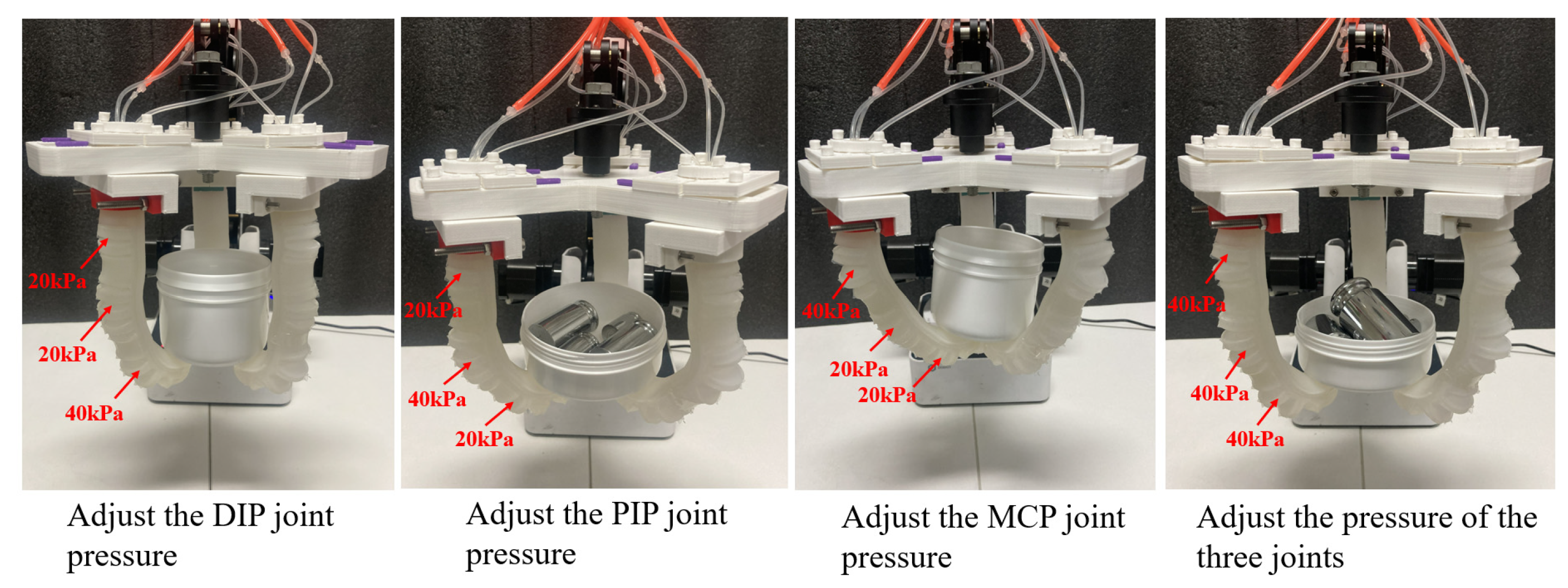
| Scheme | MCP/kPa | PIP/kPa | DIP/kPa |
|---|---|---|---|
| 1 | 10 | 40 | 10 |
| 2 | 10 | 10 | 40 |
| 3 | 20 | 40 | 20 |
| 4 | 40 | 40 | 40 |
| Scheme | MCP/kPa | PIP/kPa | DIP/kPa | Maximum End Force/N |
|---|---|---|---|---|
| 1 | 20 | 20 | 20 | 0.741 |
| 2 | 20 | 20 | 30 | 0.974 |
| 3 | 20 | 20 | 40 | 1.402 |
| 4 | 20 | 30 | 20 | 0.835 |
| 5 | 20 | 40 | 20 | 1.285 |
| 6 | 30 | 20 | 20 | 0.706 |
| 7 | 40 | 20 | 20 | 1.136 |
| MCP Pressure/kPa | PIP Pressure/kPa | DIP Pressure/kPa | Weight/g |
|---|---|---|---|
| 10 | 10 | 10 | 20 |
| 20 | 20 | 20 | 130 |
| 30 | 30 | 30 | 450 |
| 40 | 40 | 40 | 920 |
| 20 | 20 | 25 | 200 |
| 20 | 20 | 30 | 380 |
| 20 | 20 | 35 | 480 |
| 20 | 20 | 40 | 720 |
| 20 | 25 | 20 | 180 |
| 20 | 30 | 20 | 280 |
| 20 | 35 | 20 | 350 |
| 20 | 40 | 20 | 420 |
| 25 | 20 | 20 | 150 |
| 30 | 20 | 20 | 250 |
| 35 | 20 | 20 | 300 |
| 40 | 20 | 20 | 360 |
| Scheme | MCP/kPa | PIP/kPa | DIP/kPa | Weight/g |
|---|---|---|---|---|
| pitaya | 35 | 30 | 30 | 391.1 |
| mango | 40 | 40 | 40 | 714.9 |
| tin solder | 20 | 20 | 30 | 206.7 |
| laundry detergent | 30 | 30 | 40 | 496.5 |
| Scheme | MCP/kPa | Weight/g |
|---|---|---|
| plastic ball | 13 | 391.1 |
| weight | 20 | 714.9 |
| Sellotape | 17 | 206.7 |
| banana | 25 | 496.5 |
| Comparison Dimension | Humanoid Joint-Inspired Soft Gripper | Continuous Phalangeless Gripper |
|---|---|---|
| Object Shape Adaptability | By adjusting air pressure at three joints (MCP, PIP, DIP), it conforms better to object surfaces and adapts to irregularly shaped objects. | The limited grasping range makes it difficult to fully conform to non-spherical or irregularly shaped objects, increasing the risk of slippage. |
| Load Capacity | The higher stiffness allows for a maximum grasping weight nearly four times that of the single-chamber gripper, enabling stable grasping of heavier objects. | Structural limitations prevent independent joint control, making it difficult to securely grasp heavier objects. |
| Object Surface Roughness and Friction | The adjustable joint pressure increases the contact area with the object surface, enhancing friction and making it suitable for smooth or slippery objects (e.g., detergent bottles). | Poor adaptability makes it difficult to achieve good contact with low-friction surfaces, leading to lower grasping stability and a higher risk of slippage. |
Disclaimer/Publisher’s Note: The statements, opinions and data contained in all publications are solely those of the individual author(s) and contributor(s) and not of MDPI and/or the editor(s). MDPI and/or the editor(s) disclaim responsibility for any injury to people or property resulting from any ideas, methods, instructions or products referred to in the content. |
© 2025 by the authors. Licensee MDPI, Basel, Switzerland. This article is an open access article distributed under the terms and conditions of the Creative Commons Attribution (CC BY) license (https://creativecommons.org/licenses/by/4.0/).
Share and Cite
Zhu, Y.; Bao, Q.; Zhao, H.; Wang, X. Three-Chamber Actuated Humanoid Joint-Inspired Soft Gripper: Design, Modeling, and Experimental Validation. Sensors 2025, 25, 2363. https://doi.org/10.3390/s25082363
Zhu Y, Bao Q, Zhao H, Wang X. Three-Chamber Actuated Humanoid Joint-Inspired Soft Gripper: Design, Modeling, and Experimental Validation. Sensors. 2025; 25(8):2363. https://doi.org/10.3390/s25082363
Chicago/Turabian StyleZhu, Yinlong, Qin Bao, Hu Zhao, and Xu Wang. 2025. "Three-Chamber Actuated Humanoid Joint-Inspired Soft Gripper: Design, Modeling, and Experimental Validation" Sensors 25, no. 8: 2363. https://doi.org/10.3390/s25082363
APA StyleZhu, Y., Bao, Q., Zhao, H., & Wang, X. (2025). Three-Chamber Actuated Humanoid Joint-Inspired Soft Gripper: Design, Modeling, and Experimental Validation. Sensors, 25(8), 2363. https://doi.org/10.3390/s25082363