Theoretical and Experimental Investigations of Tool Tip Vibration in Single Point Diamond Turning of Titanium Alloys

Abstract
:1. Introduction
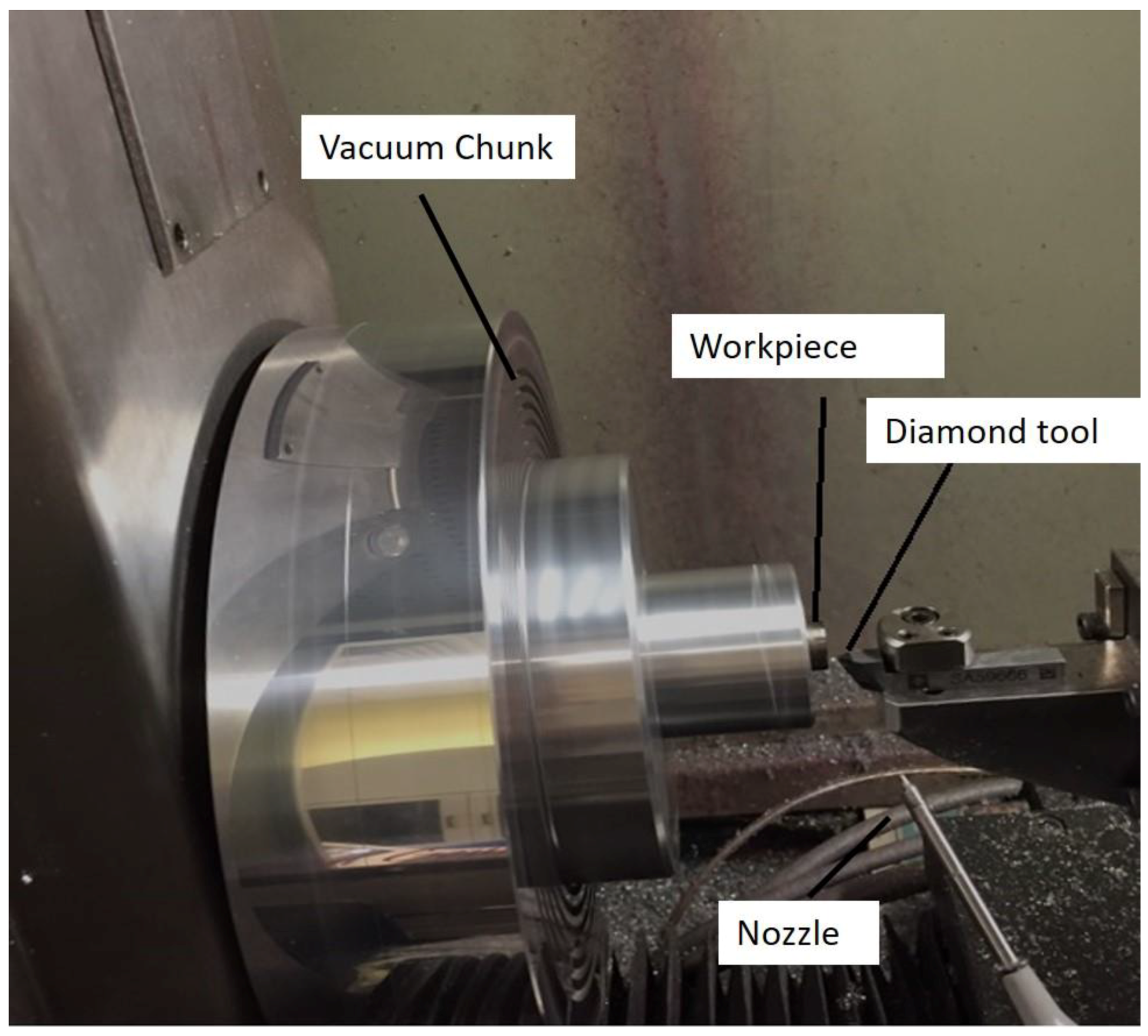
2. Experimental Setup
3. Theory
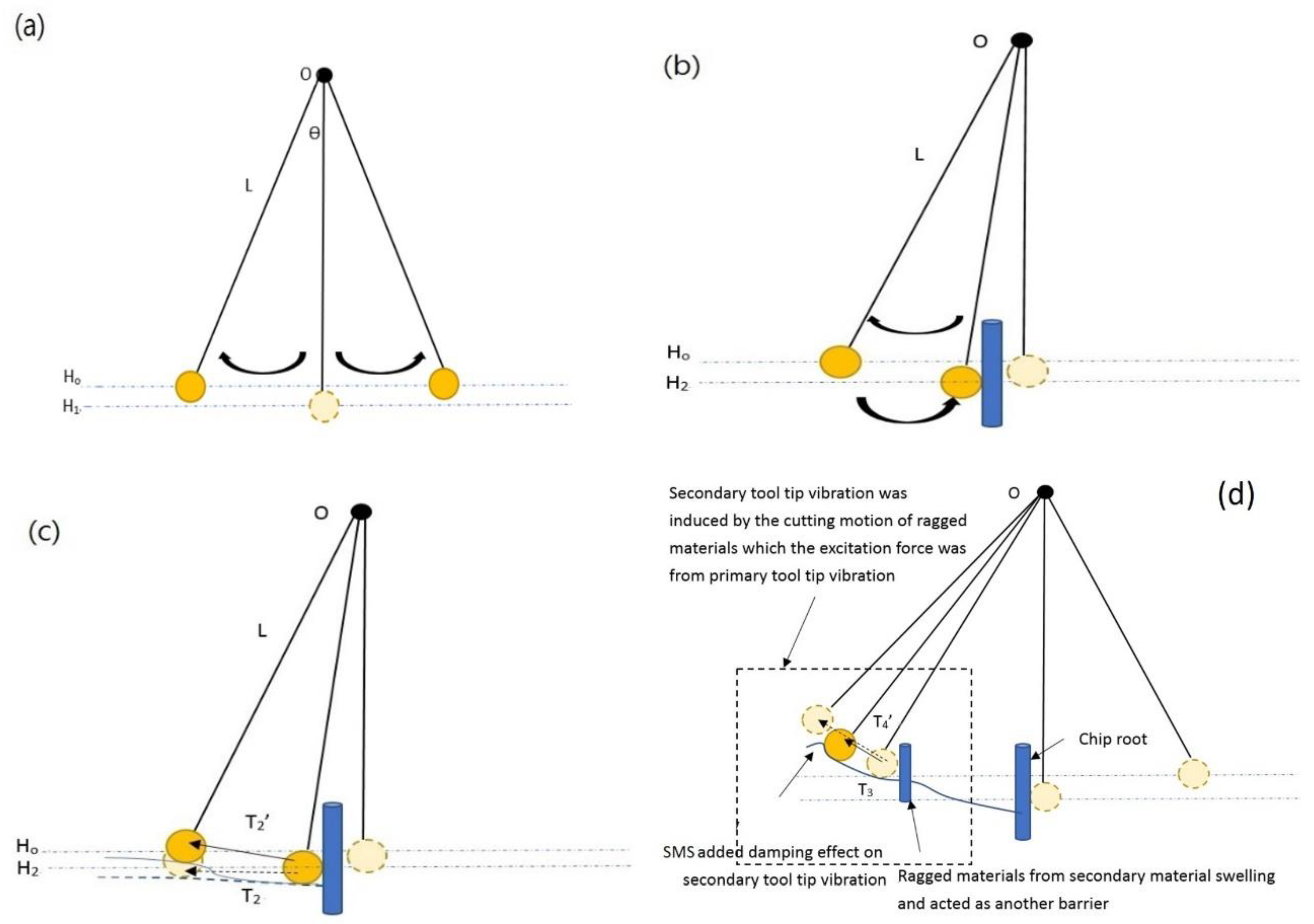
3.1. Hypothesis
3.2. Theoretical Background
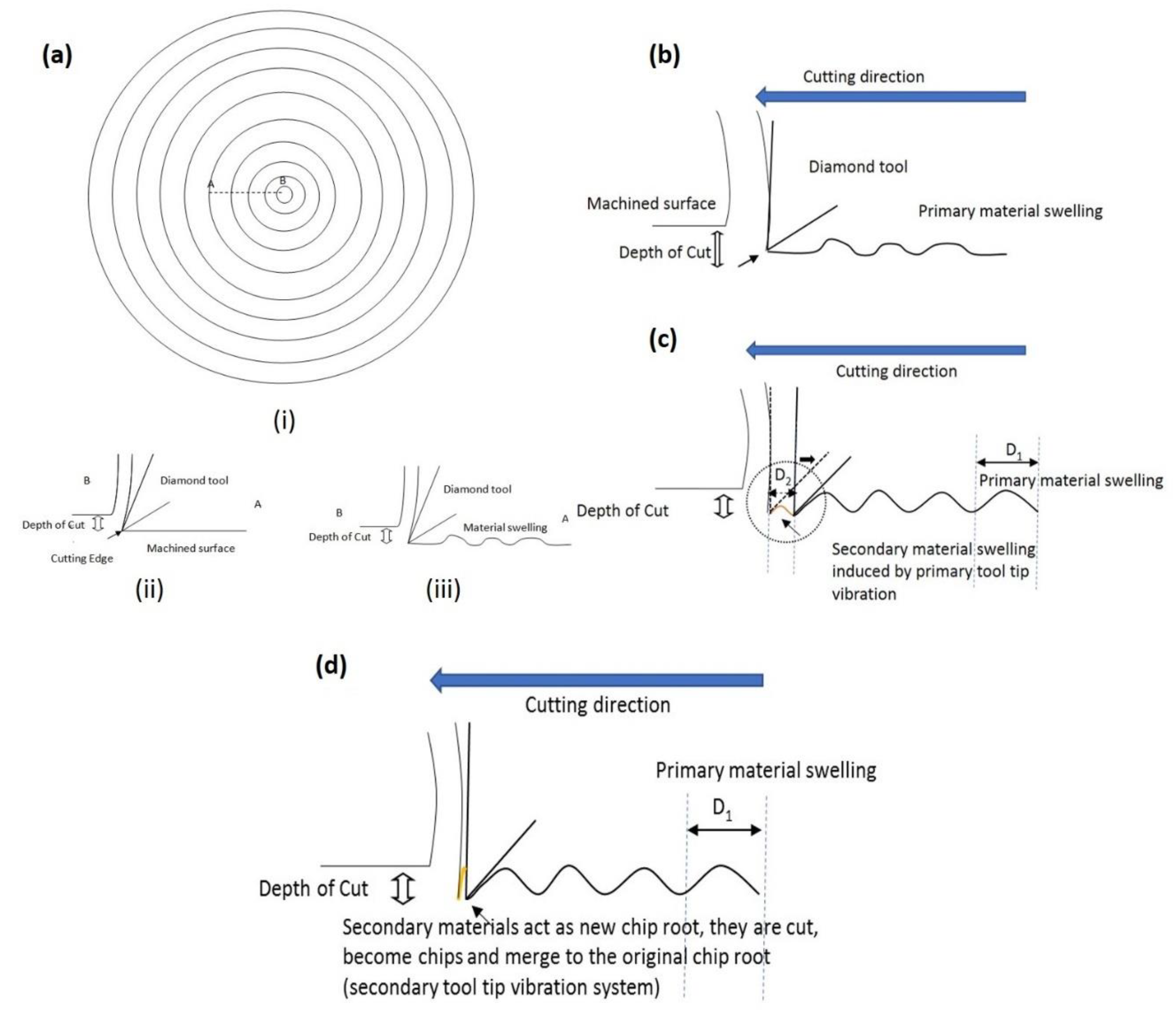
3.2.1. Identification of Twin Peak from the Tool Tip Vibration Due to PMS Caused by the Main Cutting Motion
3.2.2. Another Vibration System Induced from SMS Caused by the Tool Tip Vibration
4. Experimental Validations
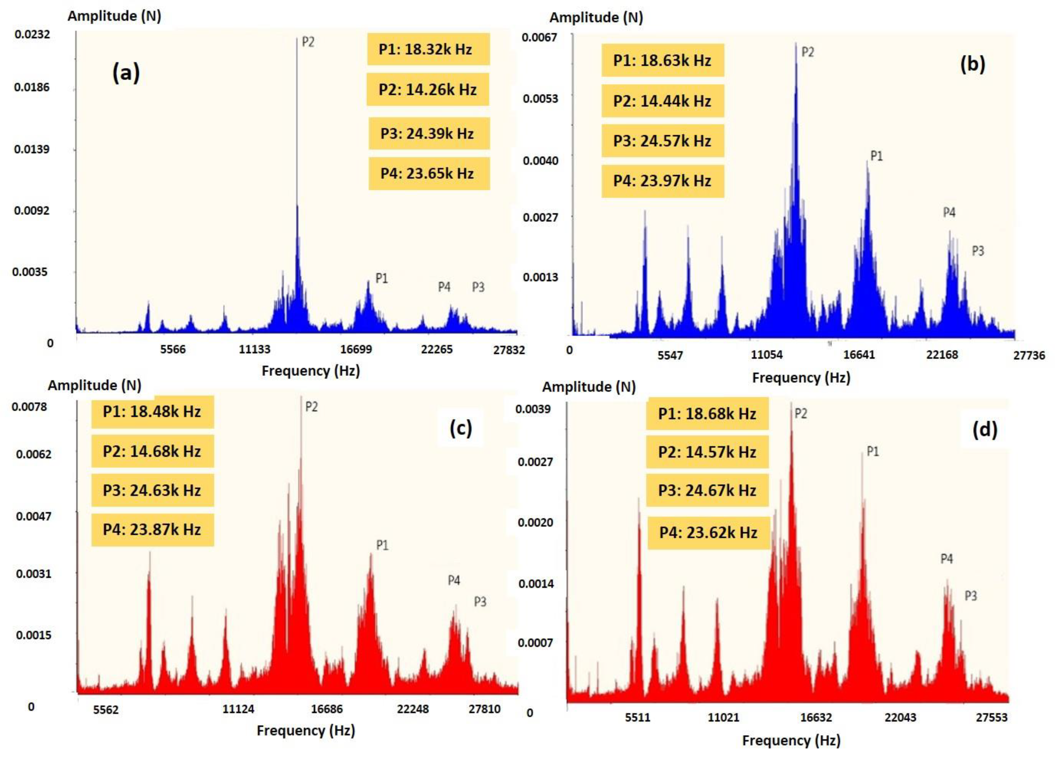
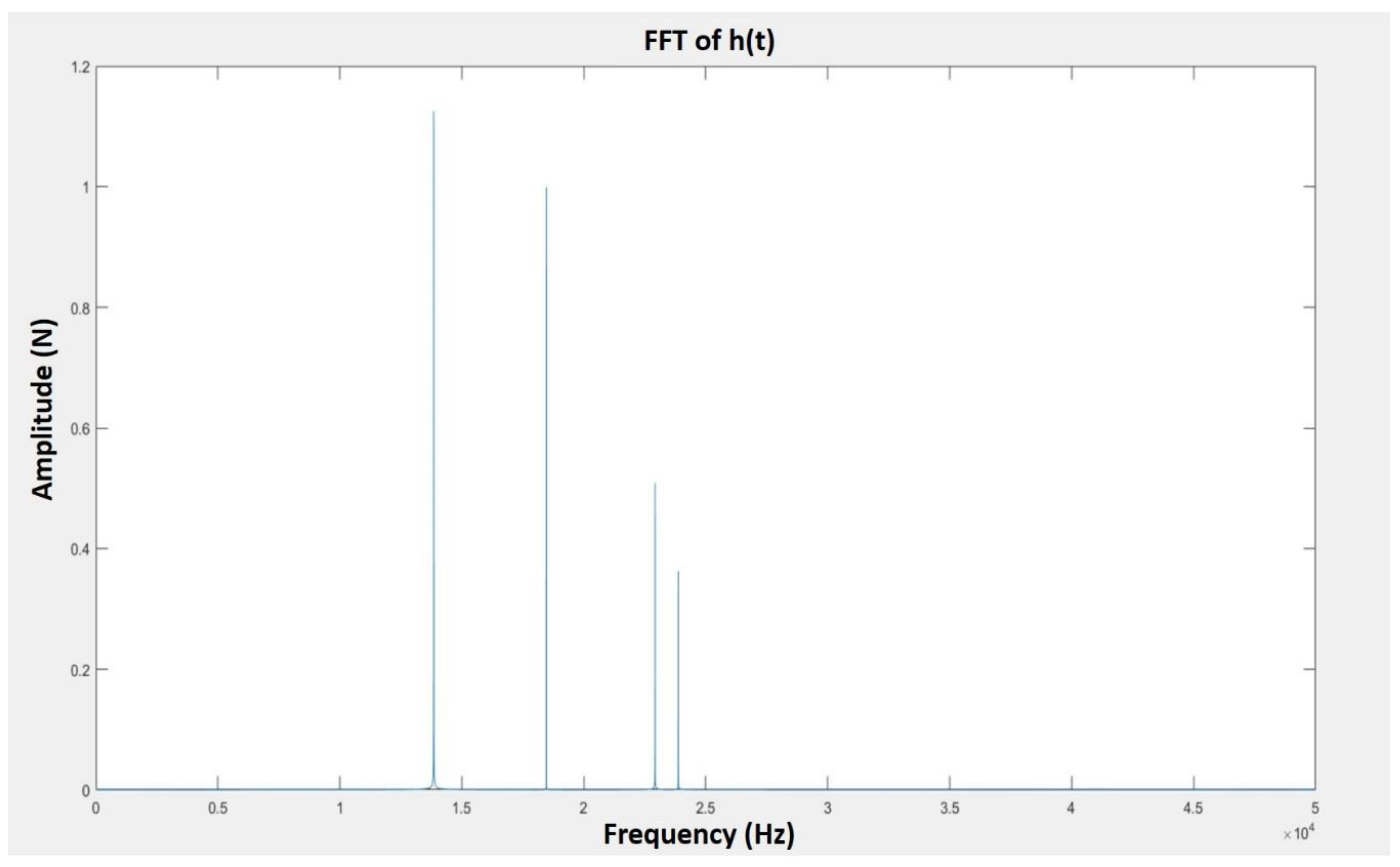
4.1. Two Individual Twin Peaks in FFT of Cutting Force of Titanium Alloys in SPDT
4.2. Experimental Validations of Surface Roughness Influenced by PMS and SMS
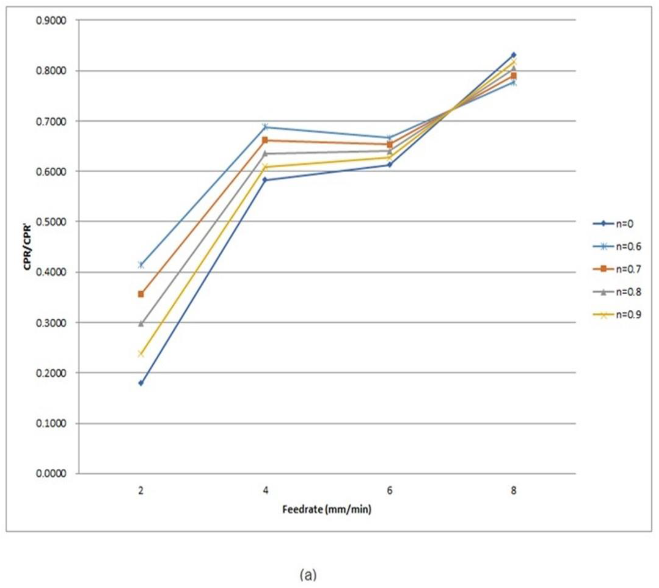
4.3. Experimental Validation of Cutting Profile Generated by PMS and SMS
5. Conclusions
Author Contributions
Funding
Conflicts of Interest
References
- Ezugwu, E.O.; Wang, Z.M. Titanium alloys and their machinability—Review. J. Mater. Process. Technol. 1997, 68, 262–274. [Google Scholar] [CrossRef]
- Narutaki, N.; Murakoshi, A.; Motonishi, S.; Takeyama, H. Study on machining of titanium alloys. CIRP Ann. Technol. 1983, 32, 65–69. [Google Scholar] [CrossRef]
- Jawaid, A.; Sharif, S.; Koksal, S. Evaluation of wear mechanisms of coated carbide tools when face milling titanium alloy. J. Mater. Process. Technol. 2000, 99, 266–274. [Google Scholar] [CrossRef]
- Che-Haron, C.H. Tool life and surface integrity in turning titanium alloy. J. Mater. Process. Technol. 2001, 118, 231–237. [Google Scholar] [CrossRef]
- Hong, S.Y.; Markus, I.; Jeong, W. New cooling approach and tool life improvement in cryogenic machining of titanium alloy Ti-6Al-4V. Int. J. Mach. Tools Manuf. 2001, 41, 2245–2260. [Google Scholar] [CrossRef]
- Su, Y.; He, N.; Li, L.; Li, X.L. An experimental investigation of effects of cooling/lubrication conditions on tool wear in high-speed end milling of Ti-6Al-4V. Wear 2006, 261, 760–766. [Google Scholar] [CrossRef]
- Guo, Y.B.; Chou, Y.K. The determination of ploughing force and its influence on material properties in metal cutting. J. Mater. Process. Technol. 2004, 148, 368–375. [Google Scholar] [CrossRef]
- Shawky, A.M.; Elbestawi, M.A. An enhanced dynamic model in turning including the effect of ploughing forces. J. Manuf. Sci. Eng. 1997, 119, 10–20. [Google Scholar] [CrossRef]
- Cheung, C.F.; Lee, W.B. Characterisation of nanosurface generation in single-point diamond turning. Int. J. Mach. Tools Manuf. 2001, 41, 851–875. [Google Scholar] [CrossRef]
- To, S.; Lee, W.B.; Chan, C.Y. Ultraprecision diamond turning of aluminium single crystals. J. Mater. Process. Technol. 1997, 63, 157–162. [Google Scholar] [CrossRef]
- Yip, W.S.; To, S. Reduction of material swelling and recovery of titanium alloys in diamond cutting by magnetic field assistance. J. Alloys Compd. 2017, 722, 525–531. [Google Scholar] [CrossRef]
- Steele, R.K.; McEvily, A.J. The high-cycle fatigue behavior of Ti-6Al-4V alloy. Eng. Fract. Mech. 1976, 8, 31–37. [Google Scholar] [CrossRef]
- Flower, H.M. Microstructural development in relation to hot working of titanium alloys. Mater. Sci. Technol. 1990, 6, 1082–1092. [Google Scholar] [CrossRef]
- Lee, W.-S.; Lin, C.-F. High-temperature deformation behaviour of Ti6Al4V alloy evaluated by high strain-rate compression tests. J. Mater. Process. Technol. 1998, 75, 127–136. [Google Scholar] [CrossRef]
- Rack, H.J.; Qazi, J.I. Titanium alloys for biomedical applications. Mater. Sci. Eng. C 2006, 26, 1269–1277. [Google Scholar] [CrossRef]
- Hao, Y.L.; Li, S.J.; Sun, S.Y.; Zheng, C.Y.; Hu, Q.M.; Yang, R. Super-elastic titanium alloy with unstable plastic deformation. Appl. Phys. Lett. 2005, 87, 91906. [Google Scholar] [CrossRef]
- Cheung, C.F.; Lee, W.B. A multi-spectrum analysis of surface roughness formation in ultra-precision machining. Precis. Eng. 2000, 24, 77–87. [Google Scholar] [CrossRef]
- Hocheng, H.; Hsieh, M.L. Signal analysis of surface roughness in diamond turning of lens molds. Int. J. Mach. Tools Manuf. 2004, 44, 1607–1618. [Google Scholar] [CrossRef]
- Zhang, S.J.; To, S.; Cheung, C.F.; Wang, H.T. Dynamic characteristics of an aerostatic bearing spindle and its influence on surface topography in ultra-precision diamond turning. Int. J. Mach. Tools Manuf. 2012, 62, 1–12. [Google Scholar] [CrossRef]
- Wang, H.; To, S.; Chan, C.Y.; Cheung, C.F.; Lee, W.B. Dynamic modelling of shear band formation and tool-tip vibration in ultra-precision diamond turning. Int. J. Mach. Tools Manuf. 2011, 51, 512–519. [Google Scholar] [CrossRef]
- Wang, H.; To, S.; Chan, C.Y. Investigation on the influence of tool-tip vibration on surface roughness and its representative measurement in ultra-precision diamond turning. Int. J. Mach. Tools Manuf. 2013, 69, 20–29. [Google Scholar] [CrossRef]
- Cheung, C.F.; Lee, W.B. Study of factors affecting the surface quality in ultra-precision diamond turning. Mater. Manuf. Process. 2000, 15, 481–502. [Google Scholar] [CrossRef]
- Wang, H.; To, S.; Chan, C.Y.; Cheung, C.F.; Lee, W.B. A theoretical and experimental investigation of the tool-tip vibration and its influence upon surface generation in single-point diamond turning. Int. J. Mach. Tools Manuf. 2010, 50, 241–252. [Google Scholar] [CrossRef]
- Lee, W.B.; Cheung, C.F. A dynamic surface topography model for the prediction of nano-surface generation in ultra-precision machining. Int. J. Mech. Sci. 2001, 43, 961–991. [Google Scholar] [CrossRef]
- Polishetty, A.; Shunmugavel, M.; Goldberg, M.; Littlefair, G.; Singh, R.K. Cutting Force and Surface Finish Analysis of Machining Additive Manufactured Titanium Alloy Ti-6Al-4V. Procedia Manuf. 2017, 7, 284–289. [Google Scholar] [CrossRef]


| Materials | Assigned Cutting Depth (μm) | Average Cutting Depth of Machined Surface (μm) | Percentage of Recovered Material Volume (%) |
|---|---|---|---|
| Copper [1] | 5 | 4.9 | 2 |
| Aluminum [1] | 5 | 4.95 | 1 |
| Titanium alloys [2] | 3 | 1.9 | 36.67 |
| Feedrate (mm/min) | Amplitude (N) | Amplitude Ratio | Surface Roughness (nm) | ||||
|---|---|---|---|---|---|---|---|
| P1 | P2 | P3 | P4 | P1/P2 | P3/P4 | ||
| 8 | 0.00278 | 0.00334 | 0.00091 | 0.00131 | 0.8315 | 0.6956 | 28.8 |
| 6 | 0.00360 | 0.00586 | 0.00158 | 0.00212 | 0.6134 | 0.7454 | 19 |
| 4 | 0.00371 | 0.00636 | 0.00162 | 0.00192 | 0.5825 | 0.8452 | 21 |
| 2 | 0.00402 | 0.02245 | 0.00168 | 0.00219 | 0.1792 | 0.7695 | 17.4 |
© 2019 by the authors. Licensee MDPI, Basel, Switzerland. This article is an open access article distributed under the terms and conditions of the Creative Commons Attribution (CC BY) license (http://creativecommons.org/licenses/by/4.0/).
Share and Cite
Yip, W.S.; To, S. Theoretical and Experimental Investigations of Tool Tip Vibration in Single Point Diamond Turning of Titanium Alloys. Micromachines 2019, 10, 231. https://doi.org/10.3390/mi10040231
Yip WS, To S. Theoretical and Experimental Investigations of Tool Tip Vibration in Single Point Diamond Turning of Titanium Alloys. Micromachines. 2019; 10(4):231. https://doi.org/10.3390/mi10040231
Chicago/Turabian StyleYip, Wai Sze, and Suet To. 2019. "Theoretical and Experimental Investigations of Tool Tip Vibration in Single Point Diamond Turning of Titanium Alloys" Micromachines 10, no. 4: 231. https://doi.org/10.3390/mi10040231