1. Introduction
Common approaches to achieve high antenna directivity include the use of antenna arrays, which require a complex feeding network, or reflector antennas, which are bulky in nature. Resonant-Cavity Antennas (RCAs) have been investigated extensively as a convenient alternative in applications requiring directivity in the range of 15–25 dBi [
1,
2,
3,
4]. An RCA is formed by placing a partially reflecting superstructure (PRS) in front of a primary source antenna (such as a slot, or dipole), above a metallic ground plane or Artificial Magnetic Conductor (AMC) [
5]. The directivity of this source antenna is significantly increased by multiple reflections between the PRS and the ground plane. The PRS can take various forms, depending on the design approach and fabrication methods used to construct the RCAs, including 3-D Electromagnetic Band Gap (EBG) structures [
6]; 2-D metallo-dielectric frequency-selective surfaces [
7]; or stacks of unprinted dielectric slabs [
8]. Thus, RCAs are also referred to as EBG resonator antennas [
9], Fabry–Perot cavity antennas [
10], and 2D leaky-wave antennas [
11].
A number of wideband RCAs having all-dielectric PRSs have been proposed with peak gain and directivity greater than 15 dBi and 3 dB directivity bandwidths that are significantly greater than the initial RCAs (1–3%) [
12,
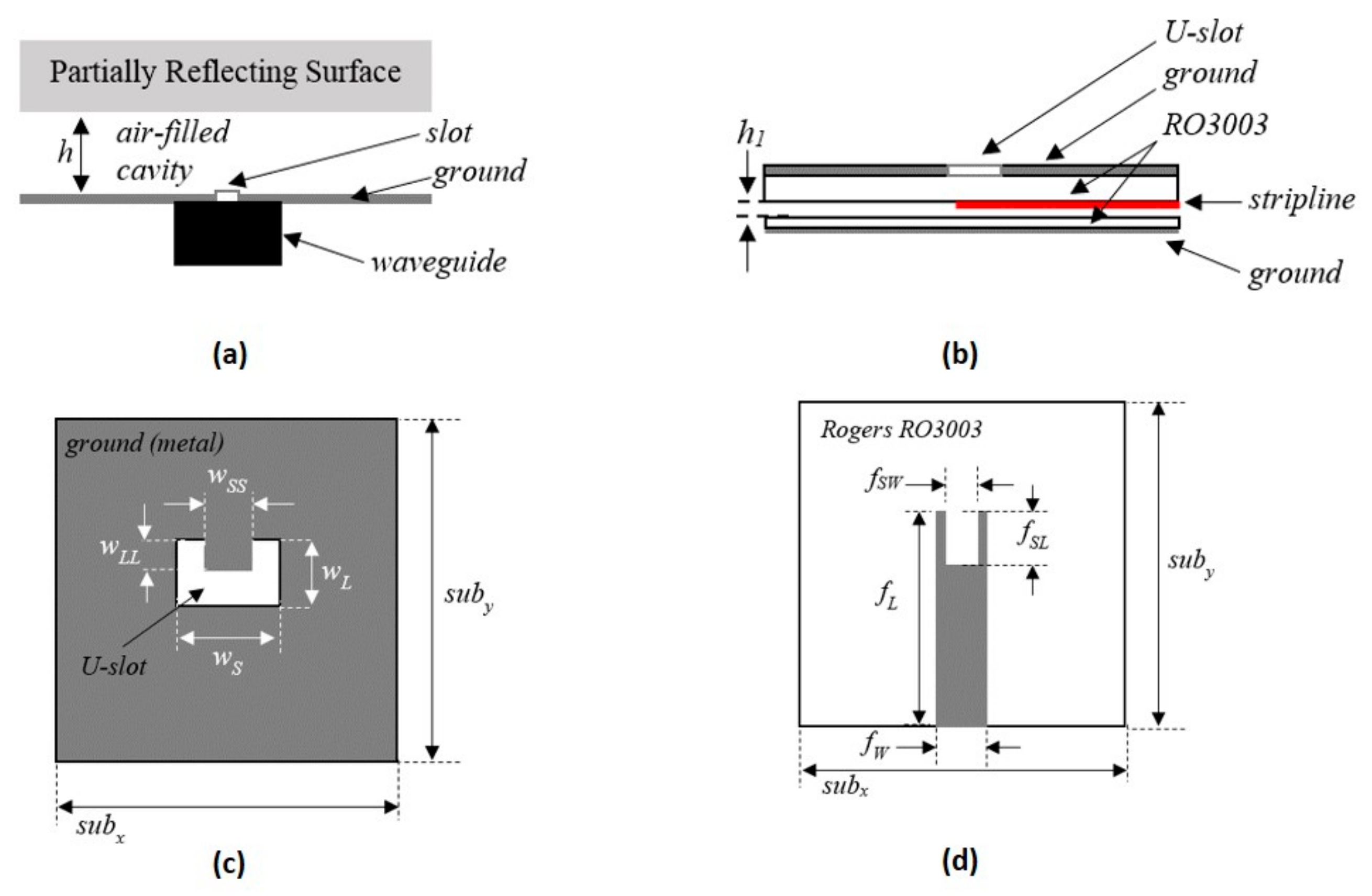
13]. However, with the increase in bandwidth, the input matching becomes increasingly challenging. This effect is more pronounced when the peak gain of the RCAs ranges between 15–20 dBi, which is required in most medium-range applications. Therefore, rectangular slots cut in a ground plane, fed by waveguide-to-SMA adaptors (shown in
Figure 1a) are commonly used to feed wideband high-gain RCAs, particularly when the bandwidths exceed beyond 20% [
14,
15,
16,
17,
18,
19]. However, standard waveguide adaptors are quite expensive, and mechanically bulky. Although they present a reasonable feeding method for antenna testing and characterization, their use adds significant cost, weight, and volume in most practical RCAs.
In this paper, a planar, wideband feed antenna is proposed, which can be used for feeding wideband RCAs. It can easily be fabricated through the standard-printed-circuit board (PCB) manufacturing process, and can easily be interfaced with any type of wideband PRS, to form a stand-alone RCA. Initially, the planar wideband feed antenna itself was numerically designed and studied using the Computer Simulation Technology Microwave Studio (CST MWS) time-domain solver. Once the desired performance was obtained, it was interfaced with a wideband dielectric PRS developed in Reference [
16] and an RCA was designed using the CST-MWS time-domain solver. The RCA fed by this planar feed demonstrated a peak gain of 18.5 dBi with a 3 dB gain-bandwidth of 32%. A prototype was fabricated and measured to validate the performance
2. Design of Planar Wideband Feed Antenna
Figure 1b–d show the schematic of the proposed planar, wideband feed antenna. It consists of two substrates in a stacked configuration, with an air-gap in between (
Figure 1b). The permittivity of the substrates is
εr = 3.02 and the loss tangent is tan δ = 0.0019. The top side of the upper substrate is metal-cladded, with a U-slot feed etched in the center (see
Figure 1c). A stripline is etched on the bottom side of the upper substrate with a U-shaped stub added at the coupling end (see
Figure 1d). The lower substrate has no metal cladding on the top side, but is backed by fully-metallic cladding. The lower substrate is placed at a distance h
1 away from the stripline, and circumvents back radiation, as shown in later sections. All the design parameters shown in
Figure 1 are given in
Table 1.
The RCA fed by a waveguide-to-SubMiniature version A (SMA) transition in [
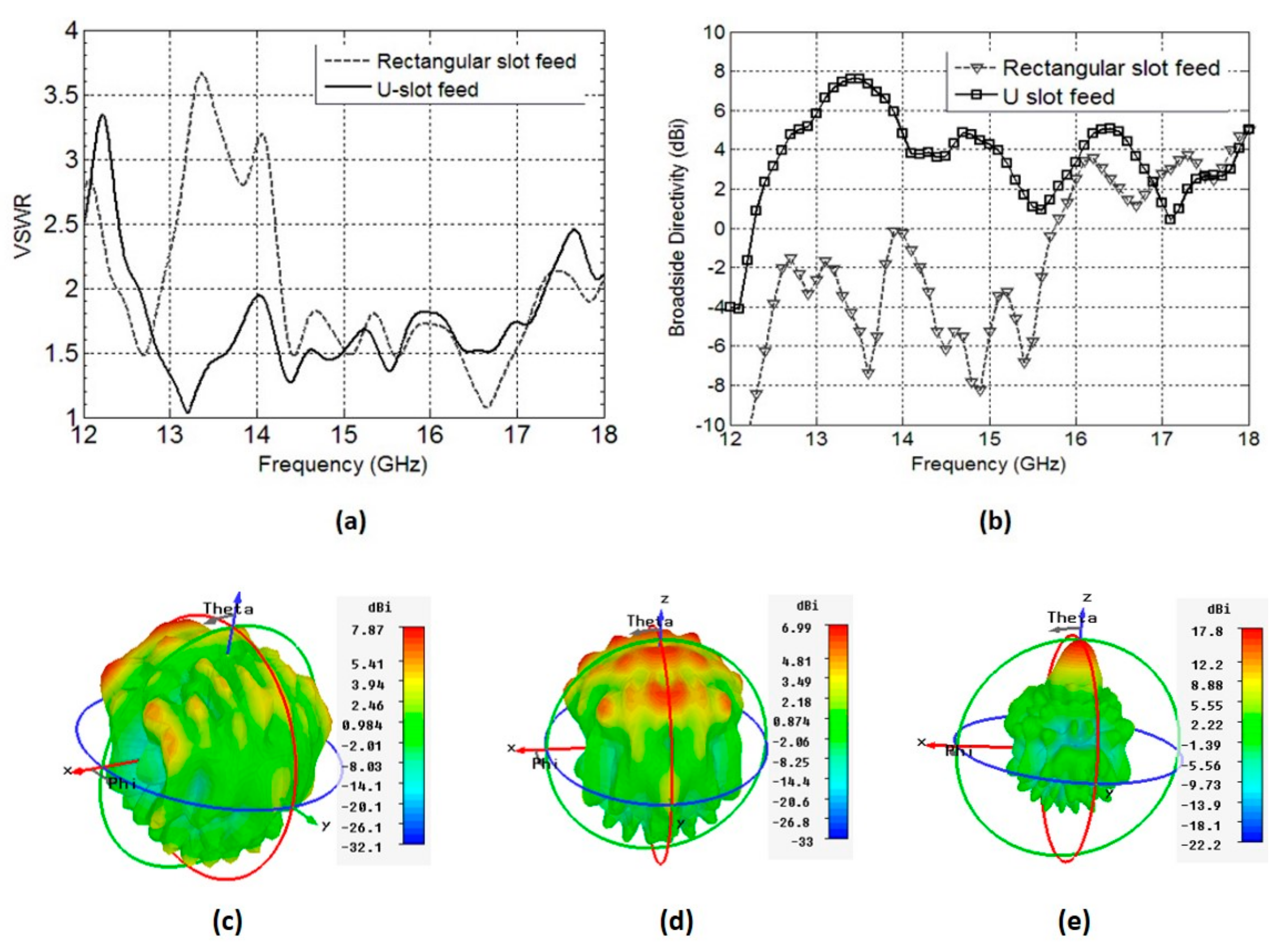
16] covers the entire Ku-band, with a peak gain of 20.7 dBi. Therefore, we selected this frequency band as a reference to replace the waveguide-to-SMA transition with a planar feed. Initially, we began with a simple rectangular slot fed by a stripline. The length and width of the rectangular slot were 13.125 mm and 9 mm, respectively. This configuration provided a VSWR 2:1 bandwidth extending from 14.2 GHz–17.3 GHz, providing matching in the upper Ku-band (see
Figure 2a). Another important aspect to consider is that a rectangular slot fed by a waveguide-to-SMA adaptor, as done in Reference [
16], provides a broadside-directed radiation pattern over the entire matched bandwidth. This characteristic is crucial to achieving high gain from an RCA. The rectangular slot fed by a stripline, however, does not radiate towards the broadside over the entire VSWR 2:1 bandwidth, as shown in
Figure 2b,c. To improve the coupling towards the broadside, the rectangular slot was modified to form a U-slot, which directed the maximum radiation towards the broadside (see
Figure 2b,d), and improved the VSWR 2:1 bandwidth to extend from 12.4 GHz to 18.2 GHz, which covers nearly the entire Ku-band. Extensive parametric studies were carried out to tune the performance of the U-slot and the stripline to achieve the optimal performance, but only the key results are presented and discussed here for brevity. The final values of the parameters that provide the best compromise between VSWR 2:1 bandwidth and broadside-directed radiation are shown in
Table 1.
3. Resonant-Cavity Antennas (RCA) Design and Interfacing with Planar Feed
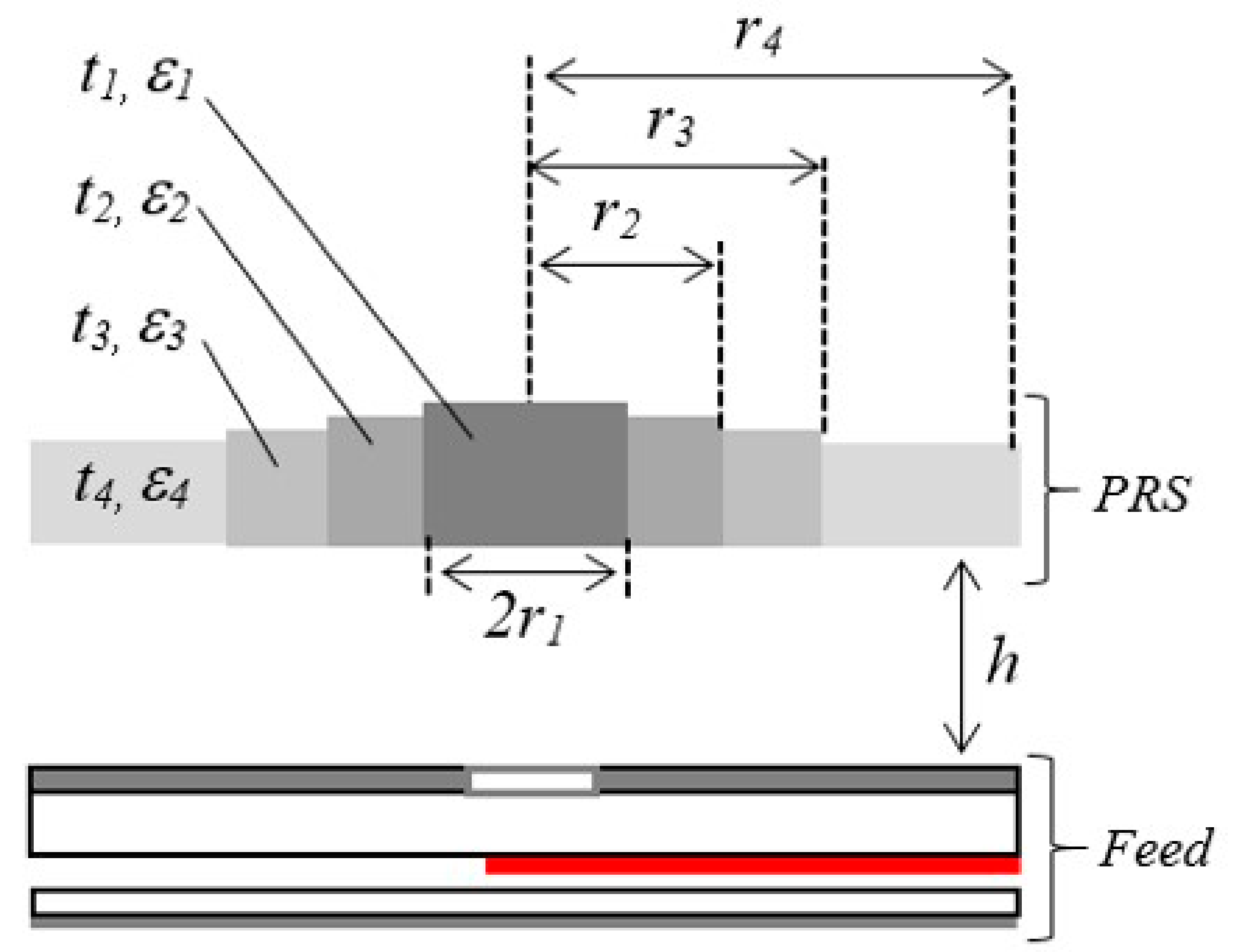
In this section, we describe the interfacing of the planar feed with a wideband dielectric PRS to design an RCA. The schematic of the wideband dielectric PRS is shown in
Figure 3. The PRS has a circular shape and a diameter D = 78 mm (2.6λ
0 at 10 GHz) and is placed at a distance h = 16 mm (~0.53λ
0) from the top part of the feed antenna, as shown in
Figure 3. In this configuration, the metallic cladding on the top side of the upper substrate of the planar feed antenna acts as a ground plane for the RCA. It is worth pointing out that the ground plane is essential to obtain wideband gain enhancement from this RCA, which was thoroughly studied and discussed in Reference [
16]. The complete design parameters of the dielectric PRS are given in
Table 2.
Figure 4 shows the broadside directivity and VSWR of this RCA, with the planar feed interfaced with the wideband PRS. The peak directivity increased from 8 dBi (feed only, see
Figure 2b) to 18.5 dBi in
Figure 4, which is a significant 10 dB increase. The radiation pattern of the RCA with U-slot feeding structure at 15 GHz is also given in
Figure 2e to show the improvement. The VSWR 2:1 bandwidth spans over 12.4–18 GHz, corresponding to 37% matched bandwidth. The matched bandwidth clearly complements the 3 dB directivity bandwidth, which is imperative to obtain an equivalent 3 dB gain bandwidth and to minimize the mismatch loss. It can be noted in
Figure 4 that the curve of broadside directivity versus frequency is not entirely flat, and has some drops at 14.2 GHz, 15.3 GHz, and 16.5 GHz, although these drops are less than 3 dB from the peak value of directivity. A close comparison of
Figure 4 with
Figure 2b shows that these frequencies approximately correspond to the frequencies where the broadside directivity of the feed antenna drops down, which in turn reflects in the broadside directivity of RCA. As discussed in
Section 2, the air gap h
1, and the dimensions of the U-shaped stub at the coupling end of the stripline, were parametrically studied to achieve the best compromise between matching and broadside directivity. These two parameters can readily influence the 3-dB directivity bandwidth, particularly when there a small drops observed in the broadside directivity, seen in
Figure 4.
Figure 5 shows the effect of slight variations in the air gap h
1, by varying the value of h
1 from 0.9 mm to 1.2 mm. It can be observed from
Figure 5 that larger values of h
1 may lead to a deterioration in the matching of the RCA (see
Figure 5a), particularly from 16–16.5 GHz and 17.5–18 GHz, whereas smaller values of h
1 can influence the drop in broadside directivity around 15 GHz, and has the potential of splitting the 3 dB directivity bandwidth into two bands (see
Figure 5b). Therefore, setting the value of h
1 = 1mm is a reasonable compromise. Similarly,
Figure 6 shows the effect of a U-shaped stub that is added and tuned at the coupling end of the stripline. In the absence of this stub, the broadside directivity of the feed antenna is reduced and, in turn, the broadside directivity of the RCA is decreased.
Figure 6 shows that, with the U-shaped stub removed, the directivity bandwidth reduces from 32% (12.8 to 17.65 GHz) to only 21% (14.2 to 17.6 GHz).
4. Measurement
A prototype of the proposed RCA interfaced with the planar feed was fabricated and measured in the NSI-700S-50 spherical nearfield anechoic chamber. Three nylon spacers were used to mount the wideband dielectric PRS above the planar feed and a SMA connector was soldered to the stripline. The prototype is shown in
Figure 7, along with the stripline assembly taken apart to show the U-shaped stub, and the U-slot etched in the ground plane. The U-slot was etched on one side of the copper cladding on the Rogers RO3003 substrate (Rogers Corporation Inc., Chandler, AZ, USA) (ε
r = 3.0 and tan δ = 0.0019) having a thickness of 3.04 mm. The stripline was laid out on the bottom of the substrate, and excess cladding was etched out, as shown in
Figure 7. The U-slot feeding structure and dielectric PRS were constructed using the parameters given in
Table 1 and
Table 2, respectively.
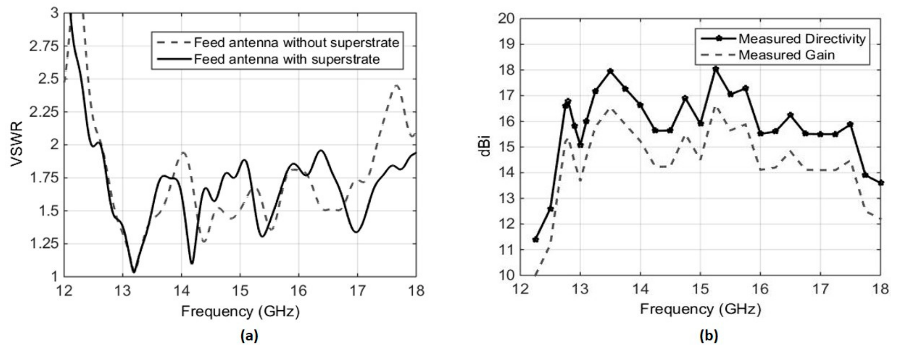
The VSWR of the planar feed antenna was measured using an Agilent PNA-X N5242A Vector Network Analyzer (Agilent Technologies Inc.).
Figure 8a shows the VSWR for the stand-alone planar feed, as well as with the planar feed interfaced with the dielectric PRS. It can be seen that, for both cases, the VSWR is less than 2 over the frequency range from 12.3 GHz to 17.8 GHz. In case of the standalone feed antenna, the VSWR rises above 2 beyond 17.25 GHz. This is because the U-slot and the U-shaped stub were optimized with the PRS integrated with the feed antenna.
The prototype demonstrated a measured peak broadside directivity and realized gain of 18 dBi and 16.7 dBi, respectively, with a measured 3 dB directivity bandwidth extending from 12.3 GHz to 17.8 GHz, as shown in
Figure 8b. The gain was measured using the gain comparison method, using standard-gain horns SGH-75 and SHG-51 as the reference antennas in the respective frequency bands. A slight difference between directivity and gain, approaching a maximum of 1.5 dB at a few data points, can be observed in
Figure 8b. This difference is attributed to two facts. Firstly, the gain-comparison method presents an inherent tolerance of ±0.5 dB. Secondly, the VSWR of the antenna is very sensitive to the air gap in the planar feed antenna, as discussed in
Section 3. While all due care was taken to maintain the air gap adequately and to keep the bottom and top layers of the feed parallel to each other, the prototype is not perfect. The measured radiation patterns of the presented antenna at three different frequencies within the gain bandwidth, shown in
Figure 9, confirm the directive nature of the antenna.
The measured performance comparisons of the proposed antenna with the previously reported RCA is given in
Table 3. As shown, the proposed antenna demonstrated significantly large bandwidth compared to that of the RCA fed by a slot-coupled WR-75 waveguide [
4] and slot coupled patch antenna [
10].

 ,
, 


