1. Introduction
Microfluidics is a technique for precise control and manipulation of micro-scale fluids especially under submicron structures [
1,
2]. As the “heart” of the microfluidic system, micropump plays a significant role in fluidic transport. Due to the important functions of micropumps, many different principles have been designed to automate the transportation.
Depending on the power source, all micropumps can be divided into two categories: Externally-powered and self-powered micropumps. Additionally, all these micropumps have huge application prospects in a wide range of fields, such as drug delivery, blood transport, Chemical and biological analysis, electronic cooling, and so on [
3,
4,
5].
Externally-powered micropumps (e.g., piezoelectric micropumps [
6,
7], syringe pump [
8,
9,
10], thermopneumatic micropump [
11], magnetic micropump [
12], and acoustic micropump [
13,
14]) use off-chip power such as electricity, mechanics, magnetism, and acoustic to drive the flow of microfluidic. Benefiting from the stability of the external components and control system, these micropumps can precisely control the speed of the microfluidic. While these micropumps have prominent advantages, they are always giant in instrument size, and thus, it is hard to integrate the external-power micropumps into microfluidic devices to realize a miniaturized all-in-one set-up.
As a result, several types of self-powered micropumps have also been developed to realize the miniaturization and portability of the total microfluidic set-up. These self-powered micropumps generally use surface tension [
15,
16], evaporation pressure [
17], hydrostatic force [
18,
19], gas diffusion/permeation [
20,
21], chemical/enzymatic reaction [
20], or biophysics to induce the fluid flow in microfluidic devices.
In the last few years, to maintain and stabilize the flow velocity inside long microchannel (especially 3D configuration) during long term, we have proposed a self-powered micropump that depends on the permeability coefficient of the silicone or PDMS elastomer to control the flow rate [
20,
22,
23,
24]. While this type of passive micropump displays advantageous performance for stable sample transport, even inside four meters’ long microchannel concerning 3D channel-configuration and high temperature microenvironment, there is a non-negligible shortcoming associated with this method, which has not been solved. The self-powered flow is virtually automated by the gas permeability of the silicone [
20,
23] or PDMS wall [
16,
24], but the specified permeability coefficient of silicone or PDMS is determined by the size distribution of mini-pores in the elastomer, which usually varies from the fabrication process, curing conditions, and the production batch, and thus increases the difficulty in accurately controlling the passive flow rate.
In this paper, we have proposed a new method to achieve the self-powered micropump, which avoids the disadvantages of the micropump automated by the gas permeability of the silicone [
20,
24] or PDMS wall [
16,
24]. An end-opened quartz capillary is utilized to replace the end-blocked silicone tube for flow adjustment, which can dramatically increase the volume of liquid transported and the flow-duration. By changing the length and the inner diameter of the quartz capillary that connects the outlet of the microchannel, the speed of the microfluidic can be precisely controlled, and thus qualified for large volume of aqueous/oil phase transport through long microchannel, which was impossible in previous reports. By using the gas permeability of the quartz capillary to control the flow velocity, no liquid will flow into the quartz tube. Benefitting from this improvement, the flow velocity is more uniform and stable. The velocity is systemically studied by adjusting the length and inner diameter of the tail quartz capillary, and the inner pressure of the fluidic conduit as well. Finally, a house-made setup microreactor of continuous-flow real-time PCRs with the sample transported inside 3D spiral chip is realized, and it only relies on a single thermostatic heater for thermal cycle.
2. Principle
Figure 1 shows a schematic illustration of the actuation mechanisms of the self-activated micropump applied to both the single-phased and the double-phased transport in the end-opened system. As we can see, it is based on the air permeability from the fluidic conduit to atmosphere through the tail quartz capillary. Thus, the permeation actually relies on the air passing through the hollow channel of the gas-impermeable quartz capillary.
Since the pressure of the compressed air captured inside the fluidic conduit is much higher than the atmospheric pressure, air molecules inside the microchip tend to penetrate to the ambient atmosphere through the hollow channel of quartz capillary. The air permeation only occurs at the outlet of the quartz capillary, which causes a decrease of the air molecules’ mole-number in the anterior end of sample plug. Based on Fick’s Law, this can be calculated by the following equation.
where
is diffusion rate,
is equivalent diffusion coefficient,
is inner air molecule concentration in the anterior end of sample plug,
represents the air pressures in the anterior end of the reagent,
is air molecule concentration of ambient atmosphere,
is diffusion distance and can be represented by the length of quartz capillary,
is the average diffusion area,
is the diameter of the quartz capillary,
is the correction coefficient between an actual condition and an ideal condition.
The equivalent diffusion coefficient of quartz capillary is only determined by the dimension of its hollow channel, but not variable to the distribution of pore-size in the wall of PDMS or silicone elastomer as previously reported.
As shown in
Figure 1a,
represents the air pressures in the posterior end of the reagent, while
represents the pressure gradient imposed in the reagent, and can be calculated by the following equation:
For an easier modeling of this new self-activated pumping system, an equivalent condition forms during the microfluidic transport, when the fluidic-flux and air-molecule-penetration is the same with each other, producing the constant pressure
If the microchannel is column-configuration, then
where
is the velocity of the microfluidic,
is the radius of the microchannel. Easily seen, the flow rate decreases if the radius of the microchannel increases.
Since atmospheric pressure
is constant, and
is also kept constant, hence the flow rate is
is constant, which can also be represented by the following equation,
where
is the pressure gradient across the hollow channel of the quartz capillary connecting the microchip to the atmosphere.
Based on the above equation, we can predict that the flow velocity increases as the quartz capillary’s length (), inner diameter (), and inner compressed pressure (, ) increase.
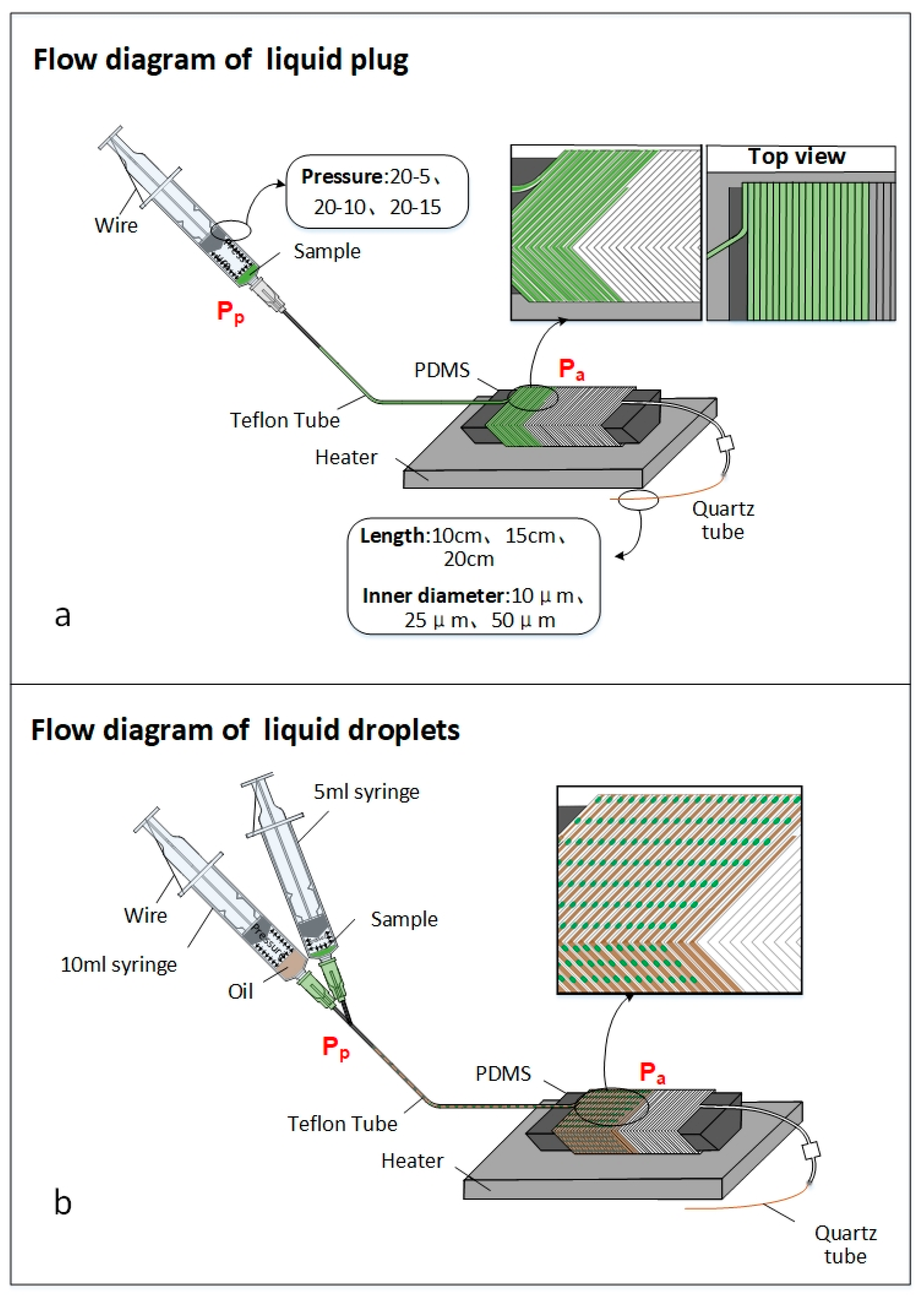
Both the flow of liquid plug and liquid droplet can be realized by this self-activated micropump. As we can see in
Figure 1b, before we set the pressure by pressing the syringe, the air pressure all through the fluidic conduit is the same. After the reagent and the oil phase (HFE 7500) are added into the insert tips of the 5 mL and 10 mL syringes, the pressure of each syringes maintains the same during the flow process. If the volume ratio between the 10 mL and 5 mL syringes is
, then the velocity ratio between the oil and the reagent is also
. If the velocity of the oil and the reagent are
and
, it can be calculated that
. Therefore, the reagent is divided into droplets by the oil, with the micropump here keeping a steady and homogeneous transport velocity when delivering reagents through a very long microchannel.
Noticeably, herein the principal depends on ideal gas but not the actual gas, which can cause a difference between the principle prediction (ideal condition) and measured experimental results (actual condition). In addition, the diffusion mechanism mainly depends on the Fick’s Law and thus is only available for very thin capillary. If the diameter of the capillary is huge, e.g., bigger than 100 μm, then other regularity such as the convection mass transfer will become the dominant effect. Under such conditions, other factors such as Peclet number of air transport can be relatively high (i.e., Pe > 2), and resulted in relatively higher flow rate than the air diffusion rule here. Since a very high flow rate is non-applicable for the downstream continuous flow PCR filed here, the flow rule activated by the convection mass transfer will not be discussed in this paper.
3. Experimentation
3.1. Flow Experiment
During the flow analysis, the device set-up consisted of two 20 mL syringes, one quartz capillary, one clamp, one 27G needle, one 5 cm-long silicone tube (OD = 3 mm, ID = 1 mm), one iron wire and Teflon tube with its inner and outer diameters to be 0.3 mm and 0.6 mm, respectively. Next, 30 µL to 50 µL green ink was added to the syringe, and then the Teflon tube was blunt-ended by a clamp. This system was activated by pressing the syringe from the scale 20 mL to a certain scale, and was fixed by the iron wire. At the end of the system, between the Teflon tube and the quartz capillary, we added a 5 cm-long silicone tube to contain the liquid in case it might flow into the quartz capillary and affected the stability of flow velocity.
After the devices have been installed, the green ink was moved to the pin of the syringe. After removing the clamp, the ink flew spontaneously into the Teflon tube under the consistent pressure inside the system.
We designed three groups of experiments to explore the flow of liquid plug under three different conditions.
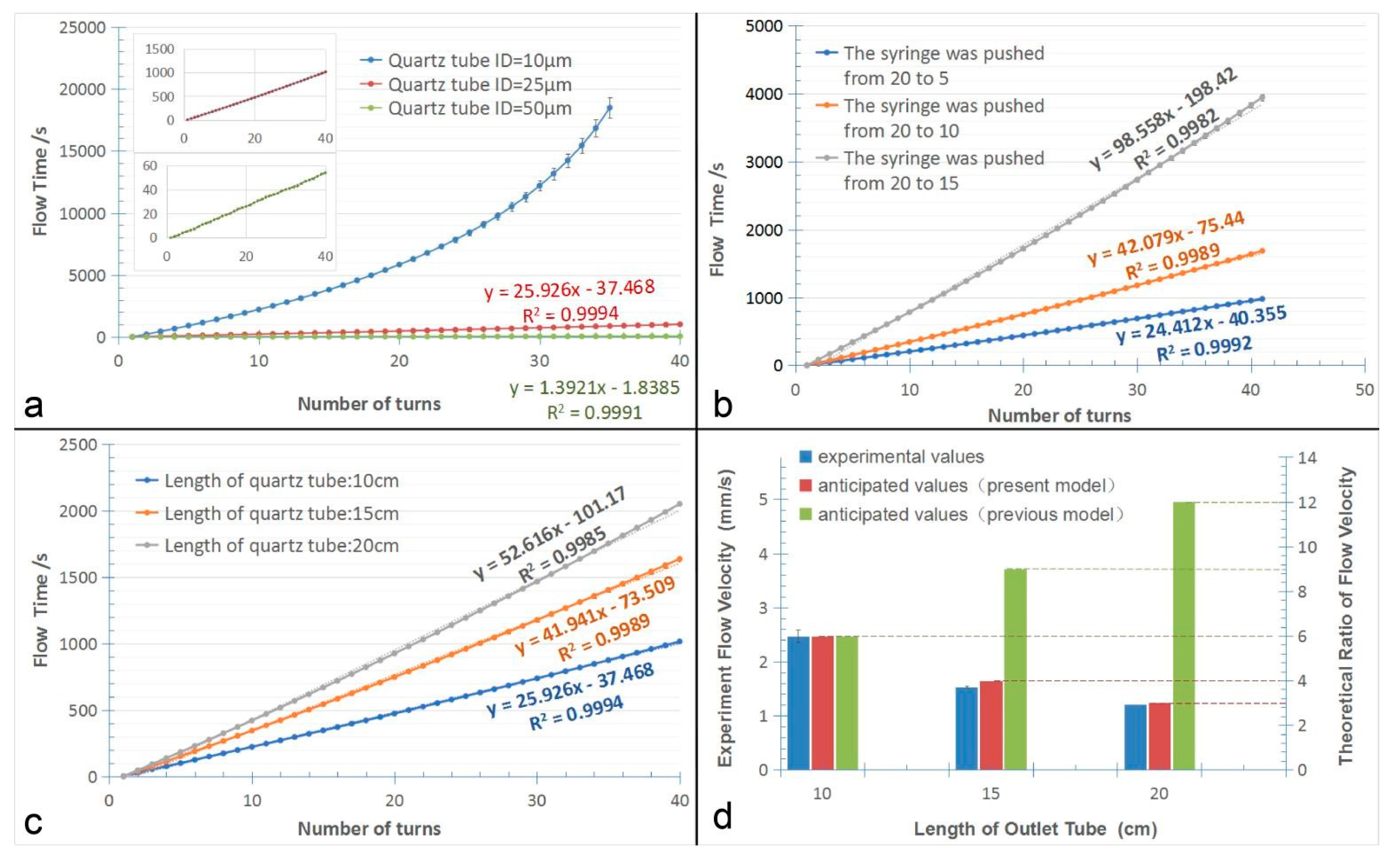
1. By changing the inner diameter of the tail quartz capillary
This experiment was carried out with three different quartz capillaries which had different inner diameters of 10 µm, 25 µm and 50 µm, respectively. To maintain the other parameters the same, the length of the quartz capillary was set to be 10 cm, and the 20 mL syringe was pressed from the scale of 20 mL to the scale of 10 mL. Each experiment was operated for three times.
2. By changing the pressure of the syringe
This experiment was carried out by varying the inner pressures of the syringe. The pistons of 20 mL syringe was pushed from scale 20 mL to scale 5 mL, 10 mL, and 15 mL, respectively. The quartz capillary’s inner diameter was 25 µm, and its length was 15 cm. Each experiment was operated for three times.
3. By changing the length of the tail quartz tube
This experiment was carried out with three different lengths of quartz capillaries, namely 10 cm, 15 cm and 20 cm. And the quartz capillary’s inner diameter was 25 µm. The 20 mL syringe is pressed from the scale of 20 mL to 10 mL. Three groups of experiments were operated, with each experiment repeated for three times.
3.2. Application in Continuous-flow On-chip PCRs
After the flow experiments, we tested the self-activated micropump system for applications of continuous-flow on-chip PCRs. Altogether, we prepared two sets of experiments to evaluate our system, the reaction of plug-based PCR and the droplets-based PCR.
1. The plug-based PCR
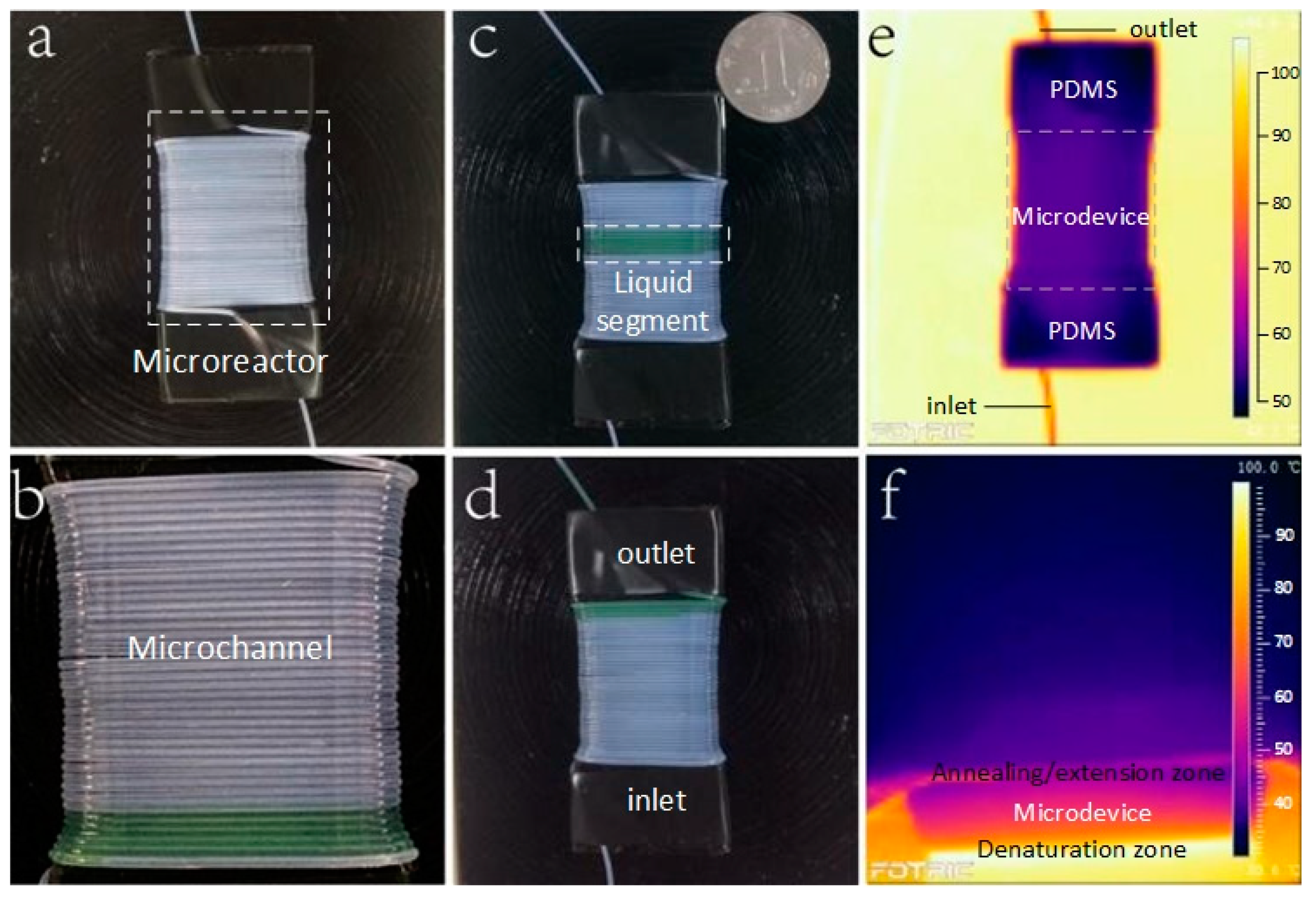
The Teflon tube was twined around a trapezoidal PDMS block for 40 rings instead of a syringe. The widths of the top and the bottom surface of the trapezoidal PDMS block are 20 mm and 10 mm, with the height and length set to be 8.5 mm and 50 mm, respectively. We cover the block with black tape for the purpose of measuring its surface temperature by IR camera. The 20 mL syringe is pressed from the scale of 20 mL to the scale of 10 mL. The quartz capillary’s inner diameter is 25 µm, and its length is 15 cm. All the connections were sealed with silicone adhesive. As shown in
Figure 2c, we put a coin at the upper right corner of the device to visually show its total size.
A single heater can achieve the thermal cycle requirement by controlling the temperature gradient of the PDMS block. In order to make sure the temperatures of the upper and lower surfaces were suitable for continuous flow microfluidic PCRs, we used an infrared (IR) camera (Fotric 220, ZXF Laboratory, Allen, TX, USA) to monitor the temperature. The tube wrapped PDMS block was placed on the top of the 95 °C heater. Through a series of parallel experiments, we adopted to make the height of the PDMS block to be 8.5 mm, so that the temperature of the upper surface reached 60 °C, which is suitable for the PCR reagent.
To prove that the micro-device can be used to continuous flow PCRs, we used a commercial PCR cycler (CFX Connect, Bio Rad, Hercules, CA, USA) as reference. By comparing the product of the two devices, we could verify the function of our system.
The PCR Reagents contained a buffer composed of 1X SYBR Premix Ex Taq II, 0.075U µL−1 TaKaRa EX Taq, 0.6 mg·mL−1 BSA (AS25483, AMEKO, Dalian, China), 1 µM forward and reverse primers, and 0.3326 ng/µL template. The primer sequences were as follows:
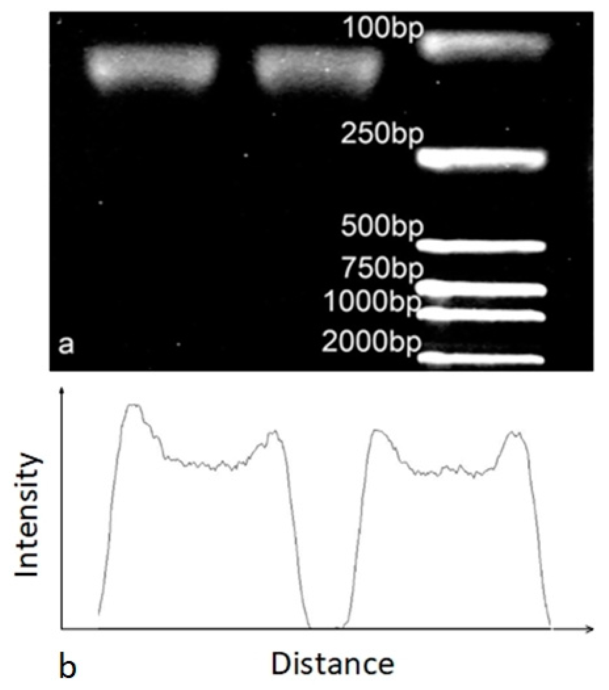
The gene of pGEM-3Zf (+) fragment was inserted into pUC57-Kan plasmid vector (Genewiz, Suzhou, China) by recombinase, and it was further used as the PCR target. After the PCR reaction, agarose powder (V900510; Sigma-Aldrich, Shanghai, China;
www.sigmaaldrich.com, MO; 2%), DL2000 DNA marker (50 × 250 µL, Peking Jialan Biotechnology Co., Ltd., Beijing, China), 0.5 × TBE buffer (PH1755, Phygene, Fuzhou, China), and Nucleic Acid GelStain (KeyGEN BioTECH, Nanjing, China) were applied to analyze the amplification result.
2. The droplet-based PCR
We slightly modify the previous plug-based PCR system as shown in
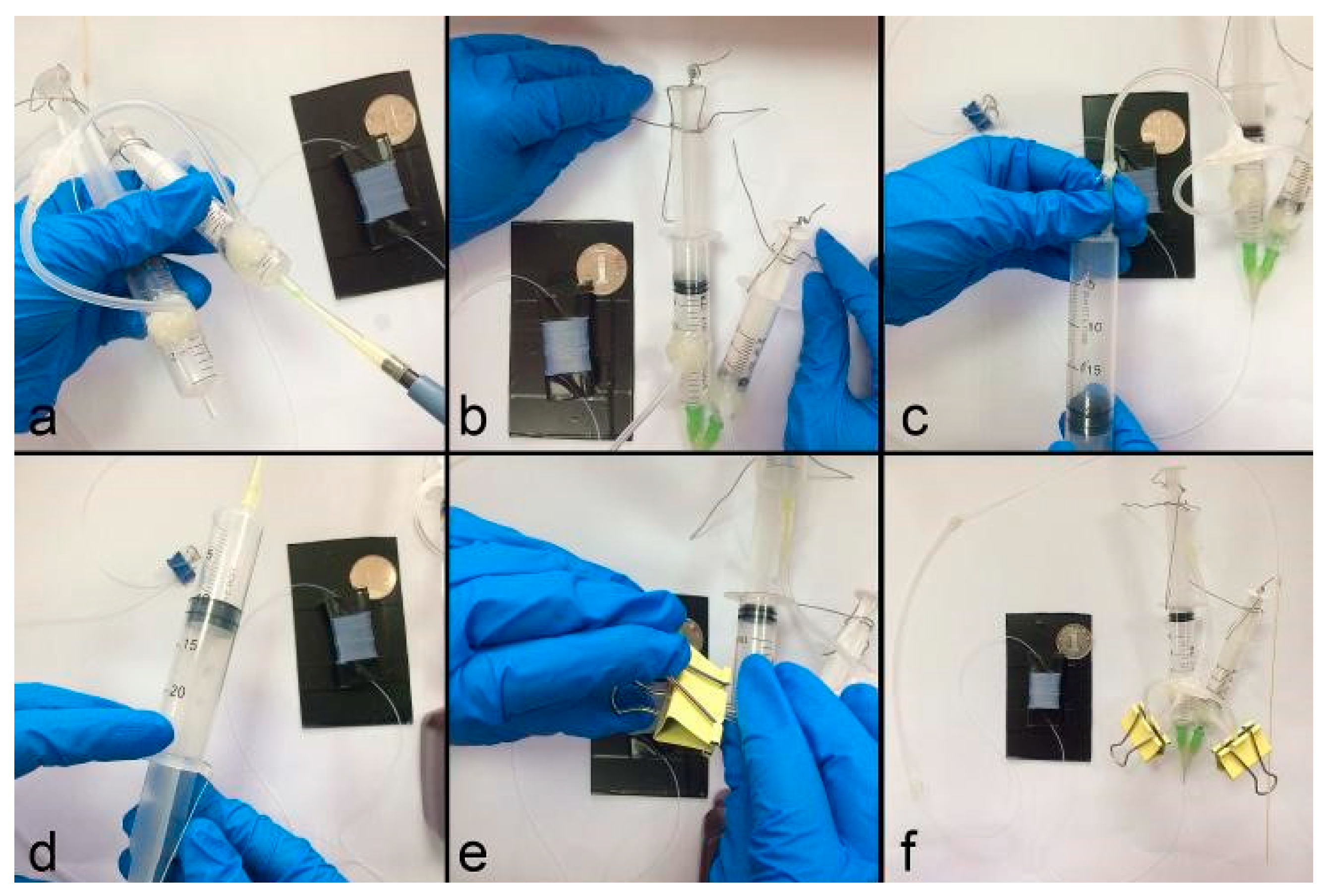
Figure 3. Instead of using one syringe to produce pressure, the droplets generation unit was activated by three pressurized syringes with original volumes of 5 mL, 10 mL, and 20 mL, respectively.
Before assembling the device, two holes were drilled (Jeben, Yongkang, China) at the 1 mL graduation of the 5 mL syringe and 4.5 mL graduation of 10 mL syringe. Three silicone tubes (ID = 1 mm, OD = 3 mm, length = 50 mm) were used to interconnect the 5 mL, 10 mL and 20 mL syringes by one T-connect (ID = 1 mm, OD = 1.6 mm). The oil-phase and the aqueous-phase were added to 10 mL and 5 mL syringes, which were then connected to the inlet of Teflon tube by two 34G needles, with the junction sealed by hot melt adhesive. The pistons of the 5 mL syringe and the 10 mL syringe were fixed at the scale of 2 mL and 9 mL by iron wires. Next the 20 mL syringe was pushed from the scale of 20 mL to 10 mL, to produce an inner pressure and fixed by a third iron wire. Then, we used two clamps to blunt the two silicone tubes between the T-connect and 5 mL, 10 mL syringes. The two syringes can be placed either vertically or obliquely to make both the oil and the reagent flow downward spontaneously [
25].
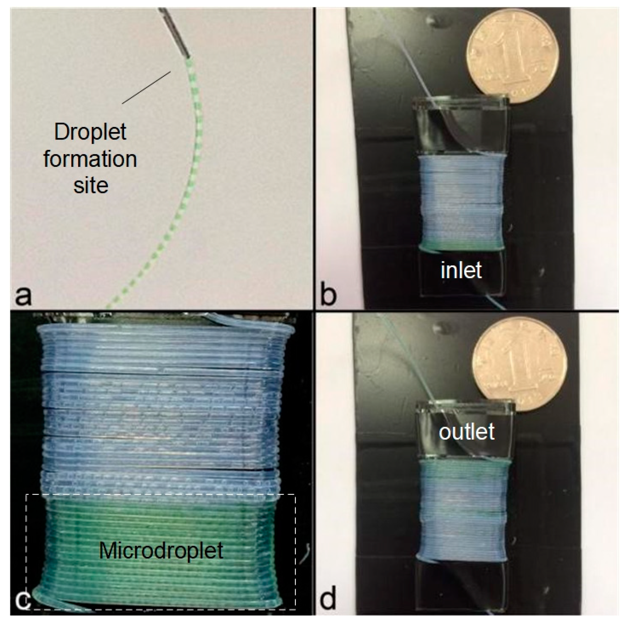
As shown in
Figure 4a, the droplets were automatically generated and transported inside the Teflon tube. The same PCR chip as previous plug experiment was used, with the length and inner diameter of the tail quartz capillary set to be 20 cm and 25 µm, respectively.
We used a single heater to achieve the temperature requirement of the PDMS block wrapped with Teflon tube. The Fluorinated oil (HFE 7500) was used as the oil phase. The other reagents were the same as the plug-based PCR experiment.
3.3. Real-time Fluorescence Detection
To prove the microdevice can be used to continuous-flow real-time PCRs, a commercial real-time qPCR (CFX Connect, Bio Rad) was used as reference. By comparing the fluorescence intensity and the products gained from the two devices, the performance of the micro-device could be verified.
PCR Reagents contained a buffer composed of 1X SRBR Premix Ex Taq II, 0.075 U μL−1 TaKaRa EX Taq, 0.3 mg·mL−1 BSA (AS25483, AMEKO), 1 μM forward and reverse primers, and 108 to 105 copies μL−1 DNA template. The primer sequences were as follows:
The gene of H7N9 was inserted into pUC57-Kan plasmid vector (Genewiz, Suzhou, China) by recombinase, which was further used as the PCR target.
The fluorescence detection unit consisted of 48 Watts LEDs array (XPE60W, Cree, NC, USA), a digital camera (Canon EOS 7D, Tokyo, Japan), a 480 nm and a 520 nm narrowband filter (Xintian bori, Beijing, China). The 480 nm narrowband filter was fixed in front of the LEDs array to offer the excitation light, and the 520 nm narrowband filter was fixed in front of the camera lens. The LEDs array was controlled by cycle relay and lighted for 5 s every 50 s, and the camera connected to the laptop automatically took photos when the LEDs array was on.
The fluorescence images were captured by aforementioned digital camera, with the parameters set as follows: F = 2.8, M = 1/20, and ISO = 2000. The images obtained was processed by the software Image J (version 1.48, National Institutes of Health, Berlin, Germany), to distinguish the light from surroundings conditions. The grayscale value was regarded as the background noise. By counting the light intensity of the liquid plug in each cycle, the fluorescence intensity curve of PCR amplification could be obtained.


