Article

Continuous ES/Feeder Cell-Sorting Device Using Dielectrophoresis and Controlled Fluid Flow

1
Graduate School of Science and Technology, Keio University, 3-14-1 Hiyoshi, Kohoku-ku, Yokohama 223-8522, Japan
2
Department of Mechanical Engineering, Faculty of Science and Technology, Keio University, 3-14-1 Hiyoshi, Yokohama 223-8522, Japan
*
Author to whom correspondence should be addressed.
Micromachines 2020, 11(8), 734; https://doi.org/10.3390/mi11080734
Submission received: 16 June 2020 / Revised: 16 July 2020 / Accepted: 26 July 2020 / Published: 29 July 2020

Abstract

:
Pluripotent stem cells (PSCs) are considered as being an important cell source for regenerative medicine. The culture of PSCs usually requires a feeder cell layer or cell adhesive matrix coating such as Matrigel, laminin, and gelatin. Although a feeder-free culture using a matrix coating has been popular, the on-feeder culture is still an effective method for the fundamental study of regenerative medicine and stem cell biology. To culture PSCs on feeder cell layers, the elimination of feeder cells is required for biological or gene analysis and for cell passage. Therefore, a simple and cost-effective cell sorting technology is required. There are several commercialized cell-sorting methods, such as FACS or MACS. However, these methods require cell labeling by fluorescent dye or magnetic antibodies with complicated processes. To resolve these problems, we focused on dielectrophoresis (DEP) phenomena for cell separation because these do not require any fluorescent or magnetic dyes or antibodies. DEP imposes an electric force on living cells under a non-uniform AC electric field. The direction and magnitude of the DEP force depend on the electric property and size of the cell. Therefore, DEP is considered as a promising approach for sorting PSCs from feeder cells. In this study, we developed a simple continuous cell-sorting device using the DEP force and fluid-induced shear force. As a result, mouse embryonic stem cells (mESCs) were purified from a mixed-cell suspension containing mESCs and mouse embryonic fibroblasts (MEFs) using our DEP cell-sorting device.

1. Introduction

Regenerative medicine is a remarkable new approach that restores damaged tissues or organs in the human body by constructing three-dimensional tissues with cells and scaffold material. Pluripotent stem cells (PSCs) are considered as a promising cell source for regenerative medicine because of their high proliferation rate and pluripotency [1,2]. Although PSCs show the potential to differentiate multiple kinds of cells to regenerate biological tissues and organs, it is difficult to establish a PSC culture so as to maintain their pluripotency because it is easily lost by disturbing the cell passage procedure and changing the physical culture conditions (vibration, temperature, etc.). Usually, PSCs have been cultured on feeder cells [2], matrix-coated substrates [3,4,5], or surface-modified substrates [6,7,8] to maintain their pluripotency. Recently, cell-adhesive matrix coating has become a major approach to culture PSCs: gelatin or Matrigel for mouse embryonic stem cells (mESCs) and induced pluripotent stem cells (iPSCs), and Matrigel or laminin fragments (LN-511, LN-511-E8, etc.) for human iPSCs [9,10,11,12]. However, in the conventional method, the PSC culture is still effective on the feeder cell layer because this method is superior in terms of the proliferation rate and pluripotency stability of the culture. Nevertheless, in the PSC culture on feeder layers, the contamination of feeder cells is not negligible when the PSCs are corrected for clinical or experimental use, such as cell sampling (gene and protein assay, histological analysis, etc.) and cell passage. Therefore, a simple and rapid method to eliminate feeder cells from the PSC culture in the cell collection process is required. Moreover, it is preferable to perform this method under damage-less and label-free conditions.
A major method for cell sorting is fluorescence-activated cell sorting (FACS) [13,14]. For the FACS method, the cells are labeled with fluorescent dyes to distinguish the type and function of cells. The FACS system detects the fluorescence of labeled cells one-by-one; therefore, the sorting accuracy is high. Another method is magnetic-activated cell sorting (MACS) [15]. The MACS system distinguishes cells using a magnetically labeled antibody. These conventional methods are superior in terms of accuracy and efficacy; however, immunological or fluorescent staining is required to label the cells [16,17,18]. From this perspective, we focused on dielectrophoresis, which handles the movement of cells by electrical force only.
Dielectrophoresis (DEP) is one of the most promising approaches for manipulating and separating cells. DEP is a phenomenon that occurs under an applied non-uniform electric field, inducing dipoles within a polarized cell in a buffer solution. The cell in a non-uniform electric field can be manipulated by DEP forces to make it move toward high or low electric field regions, depending on the relative electric property of the cells, which is related to the cell type and function. Therefore, the cell type and function can be distinguished based only on electrical properties, without any fluorescent staining or magnetic antibodies.
Many studies reported cell sorting devices using DEP phenomena to distinguish and manipulate various cells (stem cell, blood cell, cancer cell, etc.) [19,20,21,22,23,24,25,26,27,28,29,30,31,32,33,34,35,36]. These studies manipulate or separate the cells based only on the difference in DEP properties of cells, without any fluorescent staining and magnetic antibodies like FACS or MACS systems. Single cell manipulation could be performed using dielectrophoresis [19,20]. As for the cell sorting technology, living cells and other particles could be separated using dielectrophoresis [21,22,23]. The DEP sorting of living cells according to cell properties (function, kind, size, etc.) has also been performed; however, these approaches required a three-dimensional electrodes array or microfluidic flow control with a numerical simulation and validation [24,25,26,27,28,29,30,31,32,33,34]. In addition, some researchers reported accurate cell sorting methods for blood cells or oocytes [35,36]. However, the continuity of the sorting process was not sufficient. In our previous study, a novel simplified cell manipulating and sorting device using DEP and fluid-induced shear force was developed [37,38,39]. It consisted of a transparent parallel-lined interdigitated-electrode array on an indium-tin-oxide (ITO)-coated slide glass. The accuracy and simplicity of our sorting device was sufficient; however, the continuity of the sorting was not. The aim of this study is to develop a simple and continuous cell sorting system to discriminate cells based on the difference in DEP properties using a liquid flow control system.

2. Materials and Methods

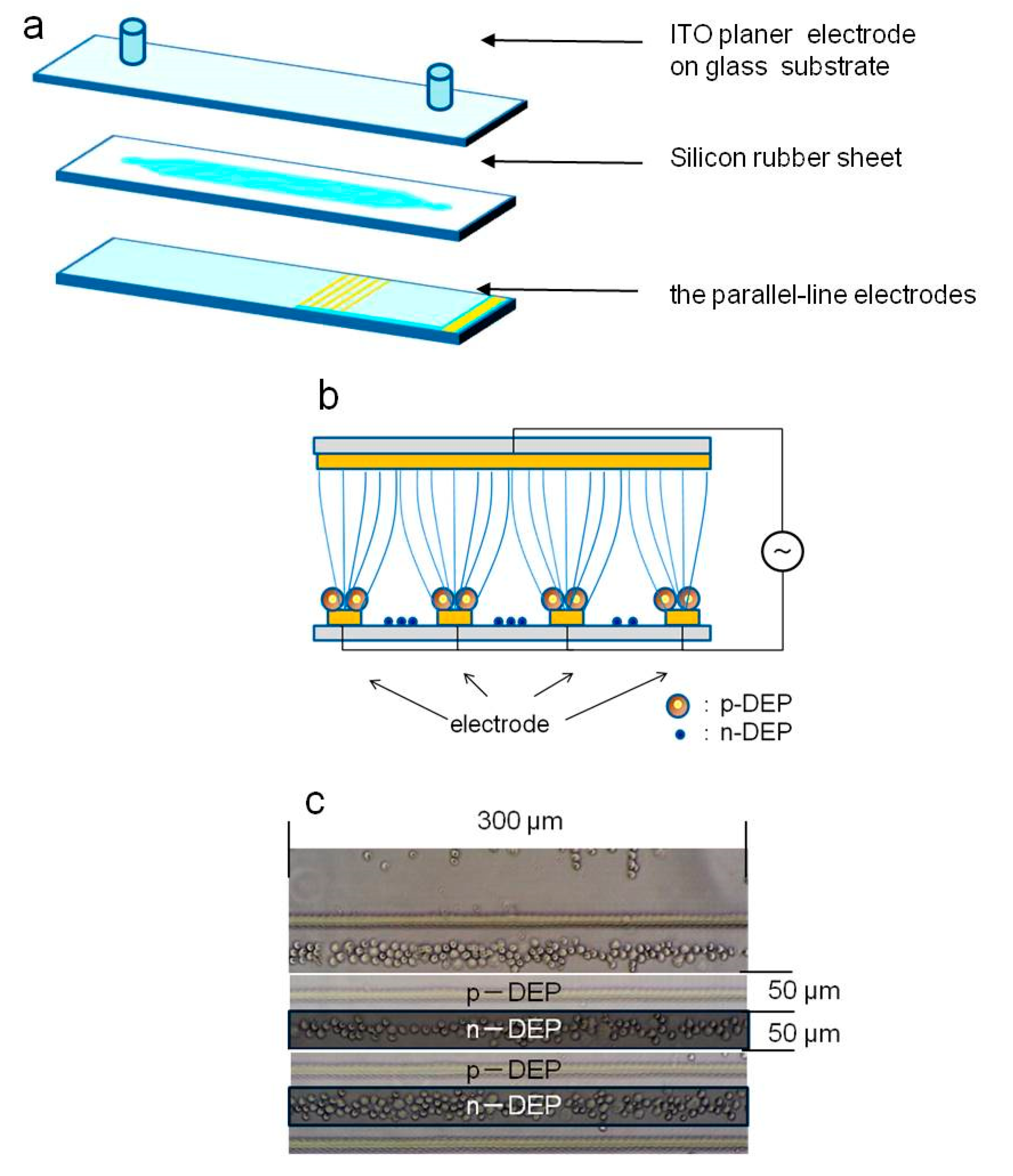
2.1. Dielectrophoresis

For a spherical particle in a non-uniform electric field, the time-averaged DEP force is generated on the particle as:
F DEP = 2 π r 3 ε 0 ε m R e [ f c m ( ω ) ] E r m s 2
where r is the radius of the microparticles, ε0 is the vacuum permittivity, εm is the relative permittivity of the surrounding medium, Re[fcm (ω)] is the real part of the Clausius–Mossoti (CM) factor, and Erms is the root mean square value of the imposed electric field [40]. The CM factor is related to the magnitude and direction of the DEP force. If the CM factor is positive, the DEP force caused on the particle is directed toward the region of high electric field intensity (positive-DEP). Conversely, if the CM factor is negative, the DEP force is directed toward the region of low electric field intensity (negative-DEP).
The CM factor is expressed as:
f c m ( ω ) = ε p * ε m * ε p * + 2 ε m *
where ε p * and ε m * are the complex permittivities of the microparticles and the suspended medium, respectively. Each complex permittivity is defined as follows:
ε * = ε 0 ε j σ ω
where ε is the relative permittivity of the particle or surrounding medium, σ is the electrical conductivity, and ω is the angular frequency of the applied AC electric field. This equation shows the dependency of the CM factor on not only the electric properties of the particle and surrounding medium but also on the frequency of the applied AC electric field. The frequency where the direction of the DEP force changes from n-DEP to p-DEP is called the crossover frequency. Our previous study reported that living cells and polystyrene beads could be separated based on DEP properties [19]. Therefore, cells could be distinguished based on differences in dielectrophoresis phenomena.

2.2. Cell Culture

In this study, mouse embryonic stem cells (mESCs) and mouse embryonic fibroblast (MEF) cells were used for the DEP cell sorting experiments. The mouse embryonic cell line, ES-B3, was obtained from Riken Bioresource center (Tsukuba, Japan), and the mitomycin C-treated MEF cells were from ReproCELL Inc. (Yokohama, Japan). The ES-B3 cells were cultured in 75-cm2 flasks in Glasgow Modified Essential Medium (GMEM) supplemented with 10% fetal bovine serum (FBS), antimycotics-antibiotics, and 1000 U/mL leukemia inhibitory factor (LIF). The MEFs were cultured in 75-cm2 flasks in GMEM supplemented with 10% FBS and antimycotics-antibiotics. Both cells were incubated in 5% CO2 and 95% humidity at 37 °C. Before the DEP experiments, the ES-B3 cells were passaged twice and MEFs were passaged once. Prior to the experiments, the cells were detached from the flasks using 0.05% trypsin and suspended in a low-conductivity buffer (LCB; 10 mM HEPES, 0.1 mM CaCl2, and 59 mM D-glucose in sucrose solution) [37,38,39]. The concentration of each cell suspension for DEP characterization was 5.0 × 10⁶ cells/mL, and the mixed ratio of ES-B3 and MEF cells for the DEP cell-sorting experiment was set at 4:6, according to a conventional on-feeder culture.

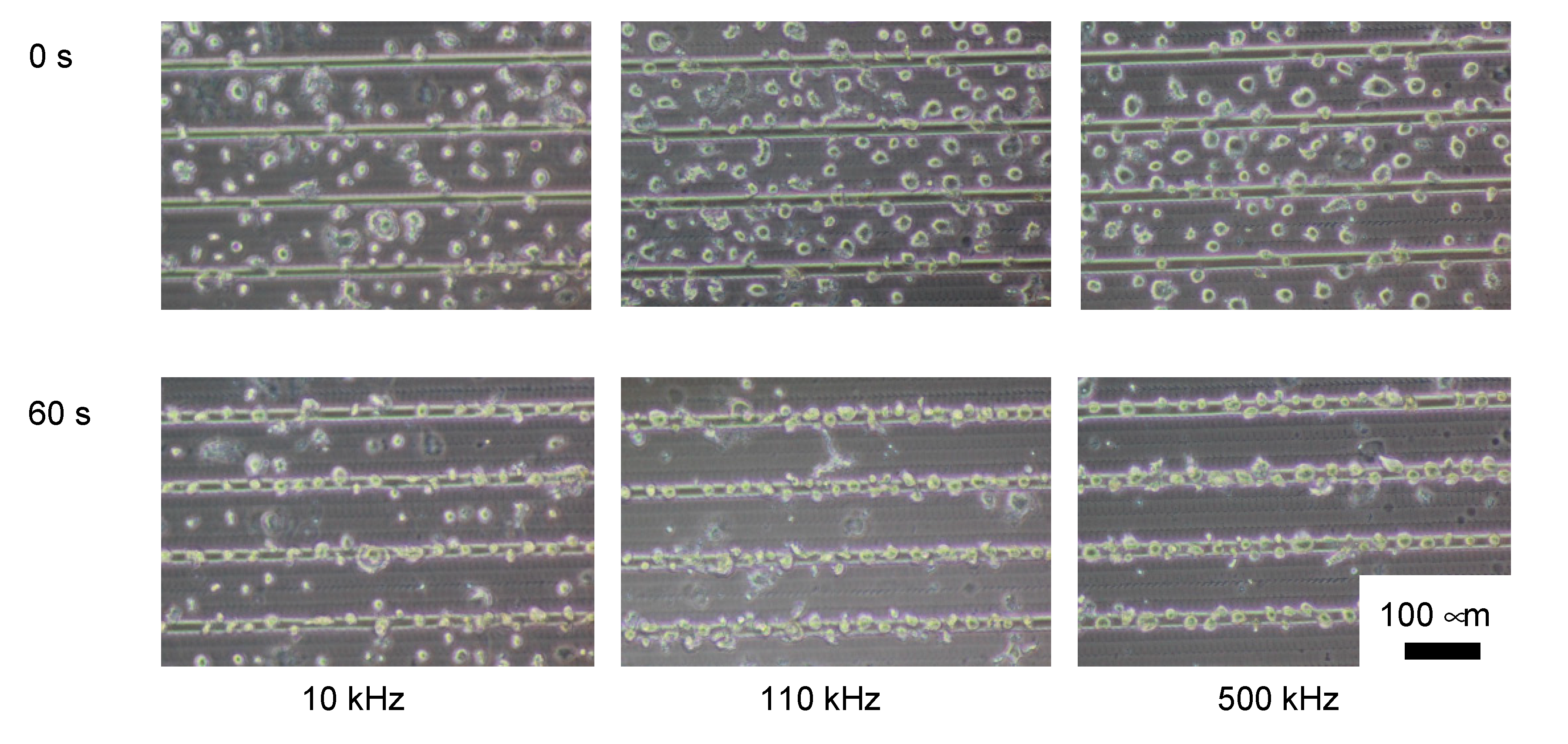
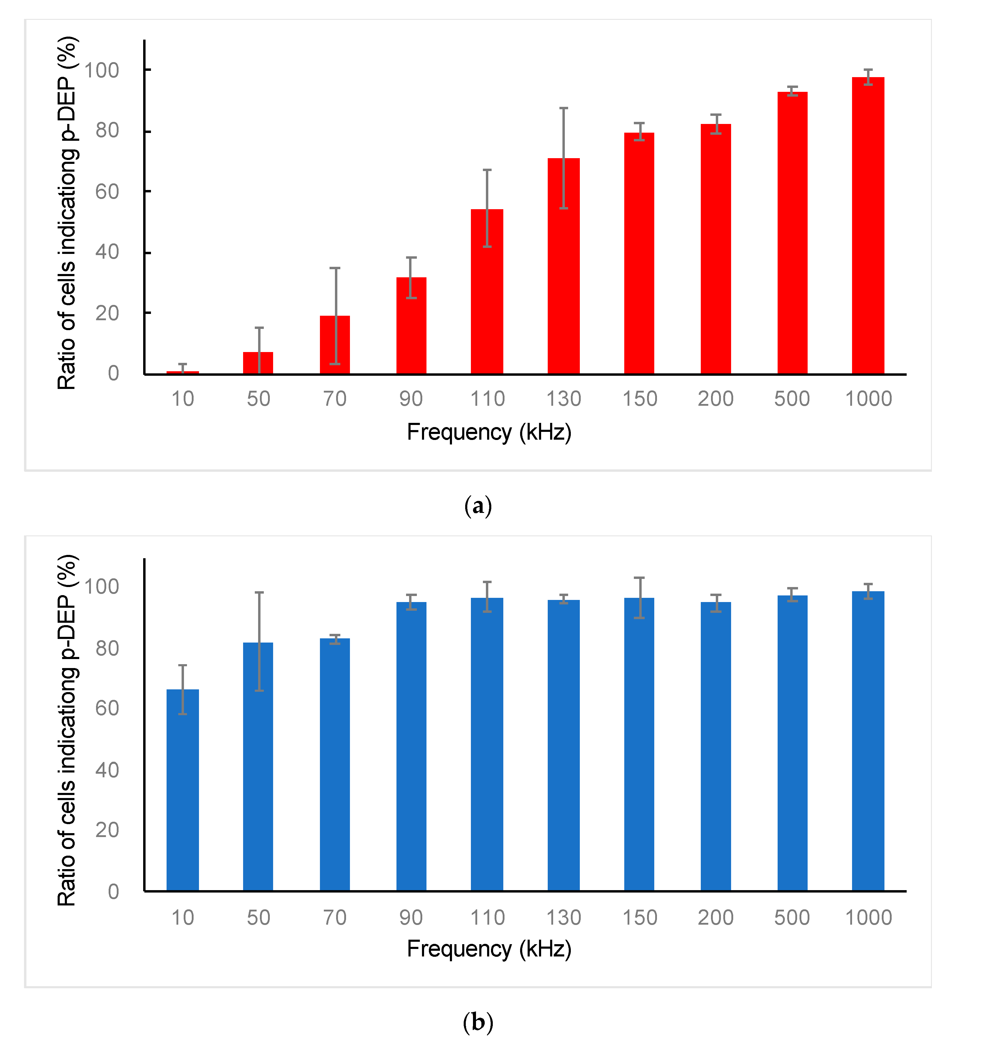
2.3. DEP Characterization of ES-B3 and MEF Cells

To sort ES-B3 and MEF cells from the mixed cell suspension, the DEP characteristics of ES-B3 and MEF cells were evaluated. To determine the crossover frequency between negative- and positive-DEP, the behavior of each cell was evaluated under various AC voltage frequencies. To cause the DEP phenomenon, a non-equal electric field was generated using transparent conductive glass (Figure 1) [37,39]. This chamber consisted of a transparent parallel-line electrode array on a glass substrate, ITO-coated glass, and a silicone rubber gasket. The parallel-line electrode array was fabricated using ITO-coated glass (Geomatec Co., Ltd., Yokohama, Japan) as a conductive substrate. The thickness of the ITO layer was 1500 Å, and the resistance was 5 Ω/sq. The parallel-line electrode was patterned using laser etching techniques. The electrode array was designed to generate a highly non-uniform electric field [37,39]. The width of each electrode line was 20 μm, and the spaces between each electrode were 80 μm (Figure 1a). The flow channel was made from a silicon rubber gasket to make a rectangular volume. The DEP chamber was formed by sandwiching the silicon rubber gasket between the parallel-line electrode array and a bare ITO-coated slide glass drilled with holes for the fluidic inlet and outlet. The thickness of the silicon rubber gasket was 500 μm. The cells were moved toward the electrodes by p-DEP and between electrodes by n-DEP in the DEP chamber (Figure 1b). The AC electric field was applied between the parallel-line electrode array and bare ITO-coated glass, using a function generator (WF1974, NF Corp., Yokohama, Japan) and amplifier (BA4850, NF Corp., Yokohama, Japan). The applied voltage was monitored by an oscilloscope (TDS1001B, Tektronix, Beaverton, OR, USA) connected in parallel. The movements of the cells within the DEP chamber were observed using a phase-contrast microscope (Nikon Eclipse TE300, Nikon, Tokyo, Japan) with a digital video camera.
For the DEP characterization, ES-B3 or MEF cell suspension in LCB was injected and subjected to an AC electric field 180 s after injection. The magnitude of the imposed AC voltage was 20 Vp-p, and the frequency was varied from 10 kHz to 1 MHz. The behavior of ES-B3 and MEF cells was observed by the digital camera on the microscope, and microphotographs were captured 180 s after each AC voltage frequency was imposed. The captured images were trimmed to 200 μm × 300 μm, and the number of cells on the electrodes (positive-DEP) and between the electrodes (negative-DEP) were counted. The ratio of cells indicating positive-DEP in the chamber was calculated to evaluate the crossover frequency. The dielectrophoretic property of a cell (indicating p-DEP or n-DEP) was assessed based on the region where the cell moved (Figure 1c). The frequency dependency of the DEP property was also evaluated as:
Ratio of cells indicating positive-DEP = NP/(NP + NN)
where NP and NN are the number of cells indicating positive-DEP and negative-DEP, respectively. When the ratio of cells indicating positive-DEP is 50%, the frequency of the AC voltage is considered a transition point from negative-DEP to positive-DEP. In this study, the crossover frequency of the DEP is defined as the frequency at which the ratio of cells indicating positive-DEP is 50%.

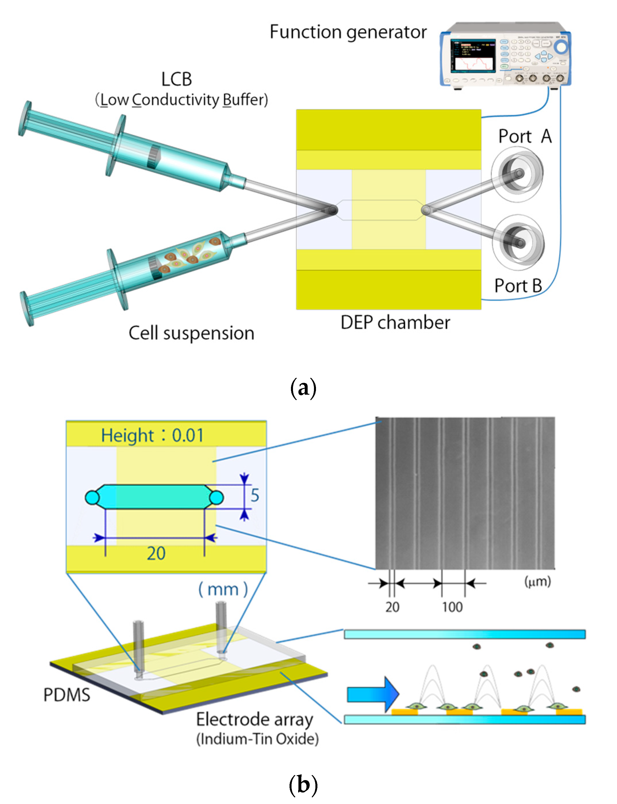
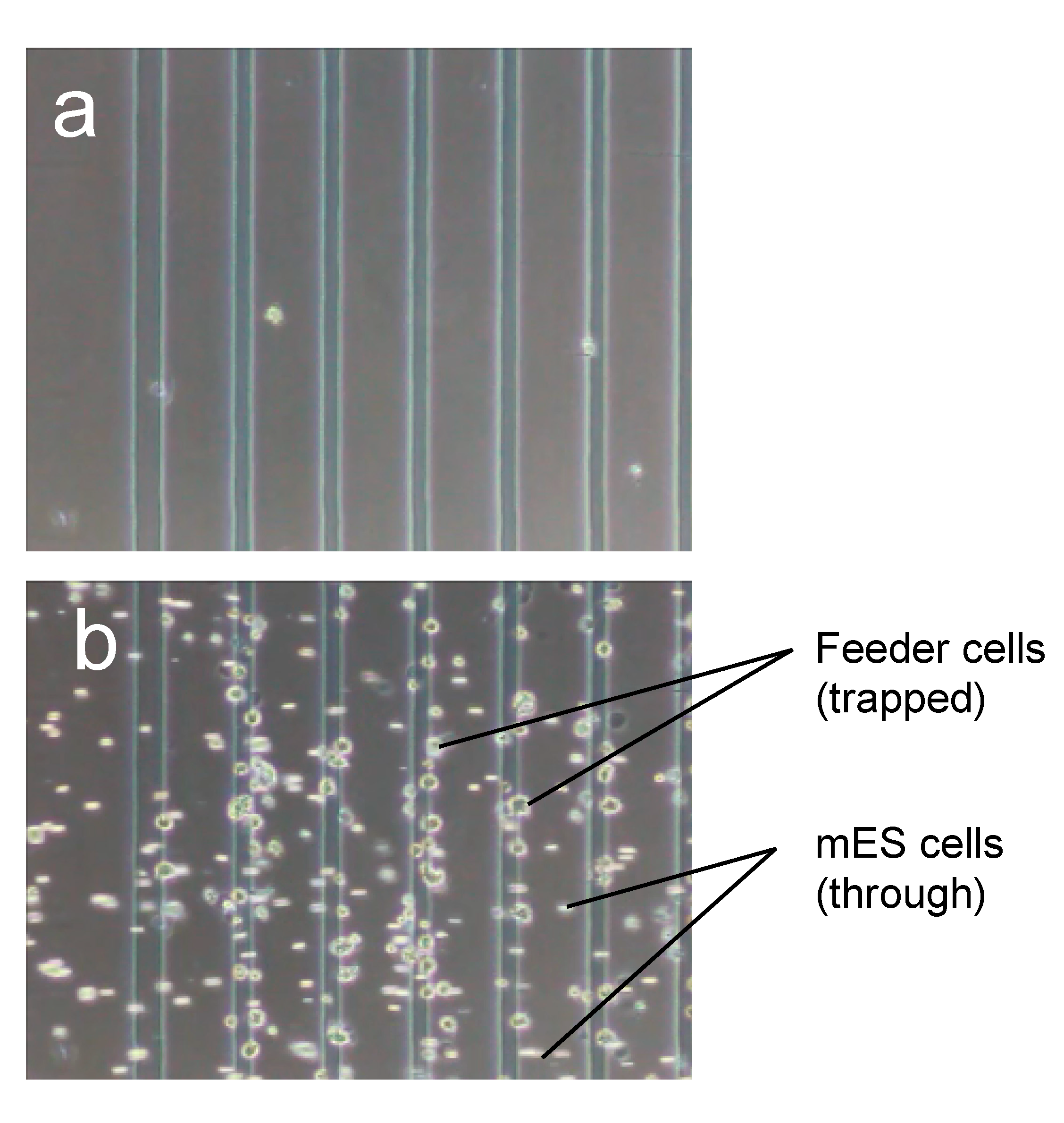
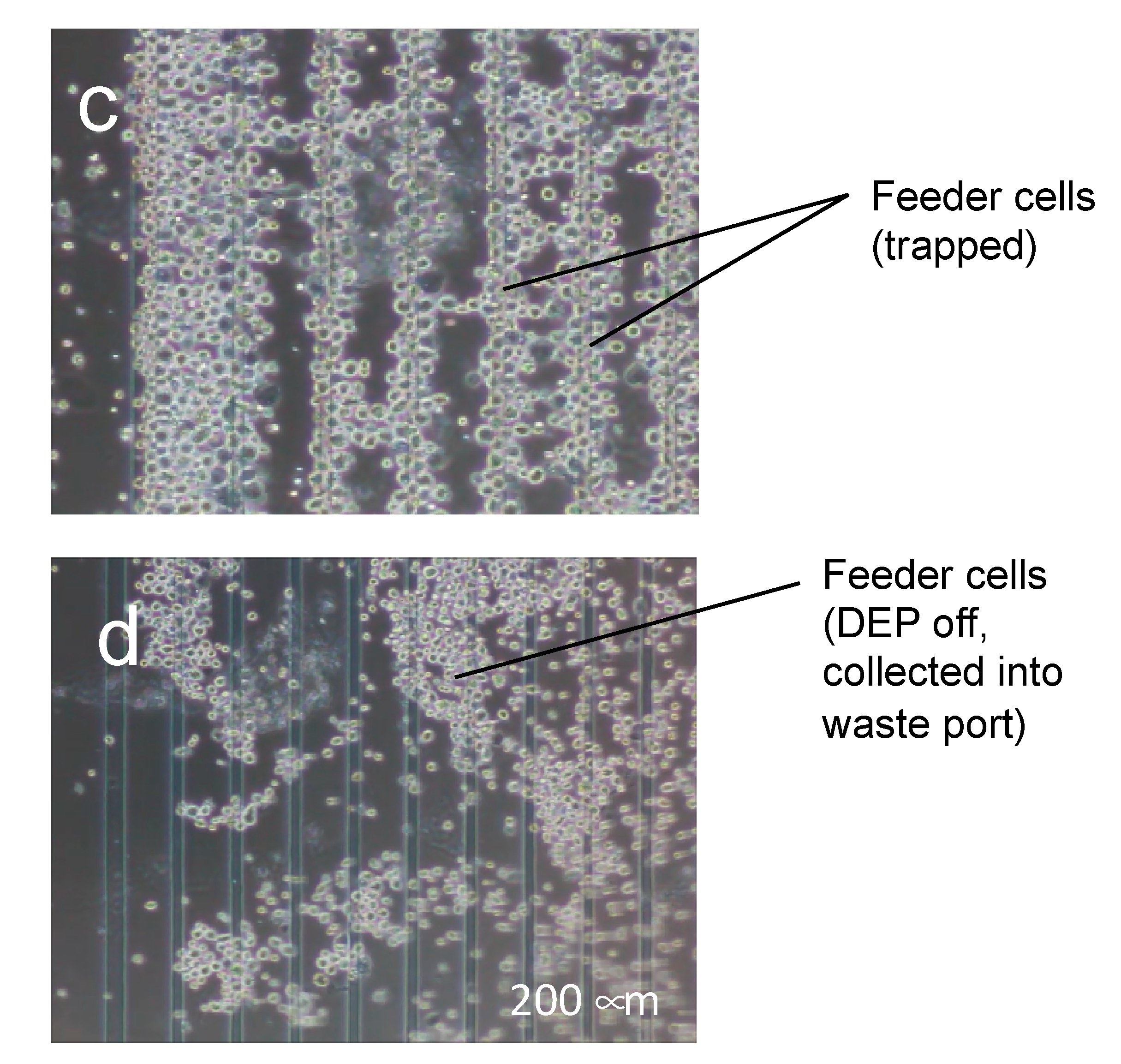
2.4. Continuous Cell Sorting Using DEP and Fluid Shear Forces

The DEP cell-sorting system consisted of a custom-made syringe pump with a PC control system, two syringes filled with the cell-mixed suspension containing ES-B3 and MEF cells and LCB solution, and the DEP chamber described in Section 2.3 (Figure 2a). The outlet of the DEP chamber was connected to two outlet ports, named port A (waste port) and port B (cell-collector port), through the switching channel. The DEP chamber was also connected to syringes containing cell suspension and LCB solution. The custom syringe pump controlled the flow rate of the cell suspension and LCB solution. The two syringes were connected to each other by a silicone rubber tube (diameter: 1 mm) and introduced into the DEP chamber. The DEP chamber for cell sorting had the same transparent parallel-lined electrode array on the lower surface of the chamber as described in Section 2.3. The flow channel of the DEP cell sorting chamber was made from a polydimethylsiloxane (PDMS) polymer sheet with a molded channel shape (Figure 2b). The DEP chamber was formed by a PDMS sheet sandwiched between the ITO glasses. The flow channel was designed to be 3 mm long from the inlet to the electrode array, 5 mm wide, and 100 μm high. The length of the flow channel was designed to ensure that whole cells were dropped on the electrode array during the cell-sorting procedure [20].
DEP and fluid-flow-based cell sorting was performed as described below (Figure 3). First, the cell-mixed suspension was injected into the chamber at a flow rate of 0.024 mL/min, and an AC electric field was imposed on the electrode array to cause p-DEP in MEF cells and n-DEP or neutral in ES-B3 cells (Step 1). In Step 1, the MEF cells were trapped on the electrodes, while the ES-B3 cells passed through the electrode array and were introduced into port B. After the line-electrode array was almost filled with the MEF cells, the AC voltage was switched off to remove the p-DEP force (Step 2). Next, the bulk LCB buffer was injected at a flow rate of 2.4 mL/min to release the trapped MEF cells from the electrode array, and they were introduced into port A (Step 3). To repeat this sorting procedure from steps 1 to 3, the MEF cells could be continuously eliminated from the ES-B3/MEF cell-mixed suspension.
Before the cell-sorting experiment, the DEP chamber was degassed and sterilized. To sterilize the chamber, the flow channel was filled with 70% ethanol for 5 min and washed twice with LCB solution. The DEP chamber was also filled with 0.2% bovine serum albumin (BSA) solution for anti-cell adhesion in the flow channel. Following the sterilization of the DEP chamber, the cell-mixed suspension was introduced into the chamber at a flow rate of 0.024 mL/min. In the sorting experiment, the AC electric field was set as 20 Vp-p at 110 kHz to cause p-DEP for MEF cells only.
To evaluate the purification efficiency of the DEP cell-sorting system, the number of injected cells (Nin) and those of ports A and B (NA, NB) were counted (Figure 4). The number of injected cells containing both ES-B3 and MEF cells was evaluated in order to compute the average number of cells passing through the first line of the electrode-array for 10 s. The numbers of cells in ports A and B were counted using a hemocytometer. The ES-B3 and MEF cells were distinguished based on the differences in the cell diameter; the diameter of ES-B3 cells ranged from 5–8 μm, and that of MEF cells ranged from 10–20 μm. The purification ratio of DEP cell sorting was determined so as to measure the existing ratio of ES-B3 cells in port B (collecting port). Moreover, the continuity of cell sorting was evaluated so as to measure the purification ratio at multiple cycles of our DEP cell-sorting system.

3. Results and Discussion

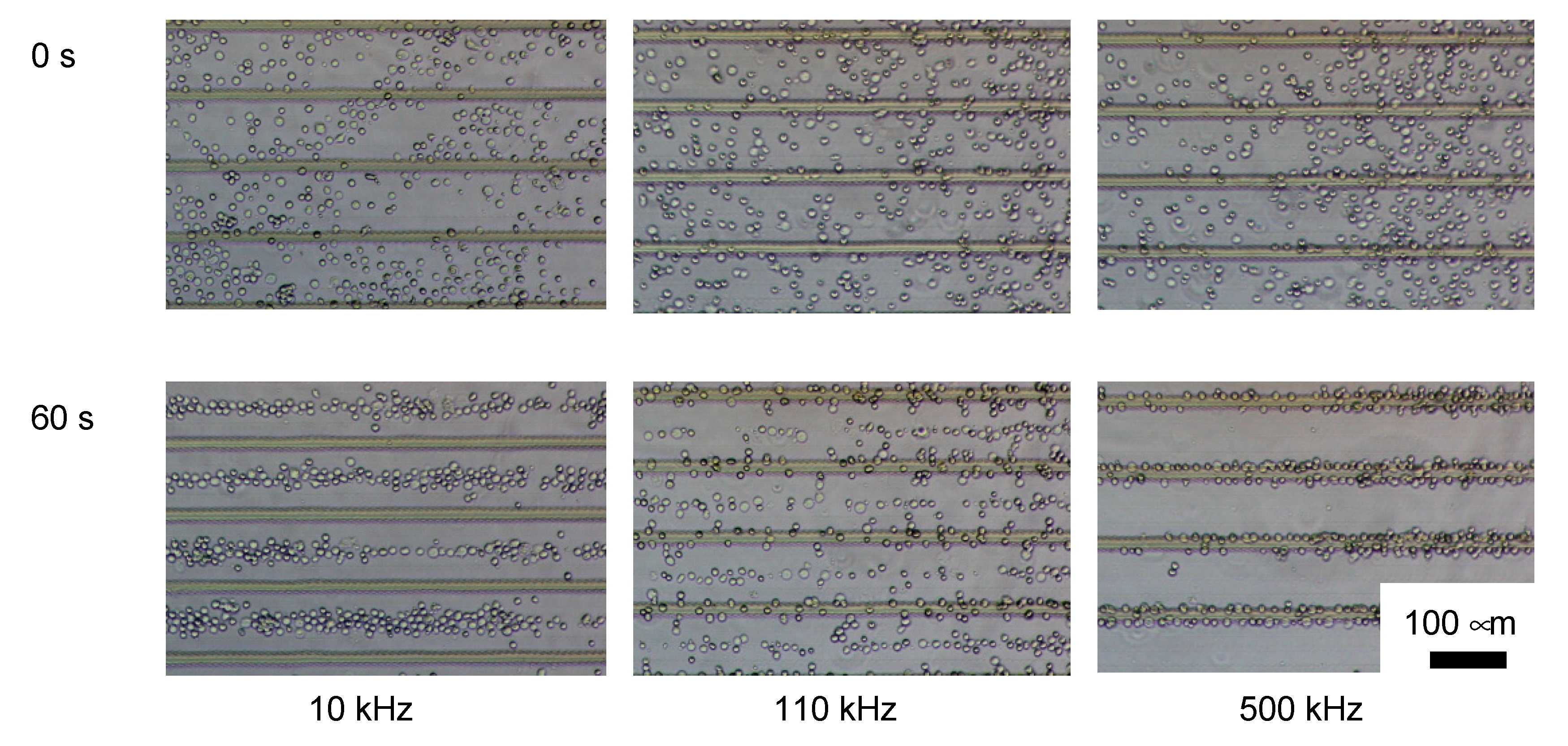
3.1. DEP Characterization of ES-B3 and MEF

The ES-B3 cells showed n-DEP under 90 kHz of the AC electric field, whereas p-DEP was over 130 kHz (Figure 5). The MEF showed p-DEP continuously from 10 kHz to 1 MHz of the AC electric field (Figure 6). The ratios of ES-B3 and MEF cells indicating p-DEP are shown in Figure 7. The crossover frequency of ES-B3 cells was considered approximately 110 kHz, whereas that of MEF cells was under 10 kHz.
The dielectrophoretic property of living cells depends mainly on the electric property and diameter of the cells [40]. Therefore, it was considered that ES-B3 and MEF cells showed different dielectrophoretic properties because of their difference in cell size and functionality. Based on this difference in the DEP property, the ES-B3 and MEF cells could be distinguished under an AC voltage of 110 kHz, where the DEP force of the ES-B3 cell was negligible and the MEF cells showed a positive DEP and were trapped on the electrode array.

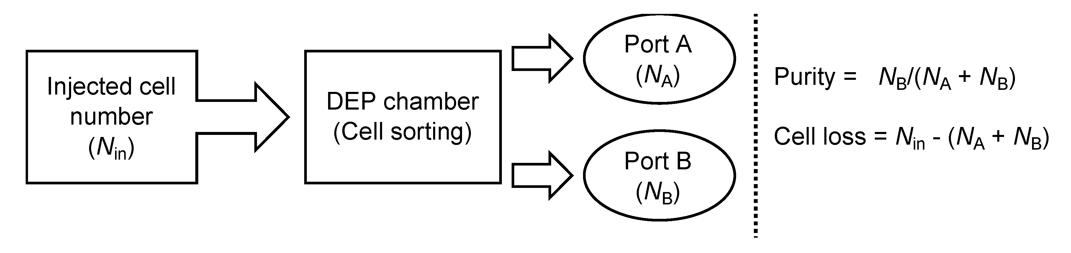
3.2. Purification Efficacy of DEP Cell-Sorting Device

In this study, a cell-sorting experiment on mESCs and feeder cells was performed using a DEP device combined with a fluid-flow control system, and the purification efficacy of mESCs was evaluated. During one cycle of cell sorting, the ES-B3 cells passed through the line-electrode array into port B; meanwhile, the MEF cells were trapped on the electrode array by p-DEP force and the trapped MEF cells were collected into port A (Video S1). Figure 8 shows the photomicrograph at each step of the DEP cell-sorting process. In step 1, the ES-B3/MEF-mixed cell suspension was injected into the DEP chamber (Figure 8a). Following step 1, the ES-B3 cells passed the line-electrode array, whereas the MEF cells were trapped on the electrode array by the p-DEP force against the fluid-induced shear force (step 2; Figure 8b). After 80% of the electrode array was covered by the trapped cells (Figure 8c), the p-DEP force was turned off in order to release and collect the MEF cells into port A (step 3; Figure 8d). Figure 8 shows the purification ratio of ES-B3 cells in port B for multiple cell-sorting cycles. The measured purification ratio of ES-B3 cells was about 59% before cell sorting and increased to about 94% in port B after the first cycle of cell sorting. The purification ratio decreased to approximately 90% during five cycles (Figure 9). The decrease in the purity of ES-B3 cells was derived from the residual cells in the corners of the chamber or the connective regions of the silicone rubber tubes. However, the purity of ES-B3 cells reached a plateau at approximately 90% and did not change after 10 cycles of cell sorting (data not shown). Therefore, the continuity and efficacy of DEP cell-sorting can be maintained if a large amount of cell sorting is required.
There are superior conventional cell-sorting methods, such as FACS and MACS, for evaluating the cell type or cell function quickly and accurately. Although these methods are effective for cell sorting, the labeling of cells by antibody or fluorescent dye is required [4,5]. Our newly developed DEP cell-sorting system does not require antibodies, fluorescence dyes, magnetic beads, or expensive equipment. In addition, the process of our DEP cell-sorting system was simple when compared to other DEP cell-sorting systems [41,42,43,44,45,46], with no complicated processes and with a high extensibility. Furthermore, our DEP cell-sorting system does not require a numerical analysis of the fluid-flow in the DEP chamber. By using a multiplex DEP-chamber or by extending the width of the chamber, the throughput of the DEP cell-sorting system could be larger. Therefore, our DEP-cell sorting system would be applicable for research and clinical uses requiring a large number of purified cells.

4. Conclusions

In this study, a novel DEP cell-sorting device using dielectrophoresis and fluid-induced shear force was developed in order to sort mouse embryonic cells and feeder cells. As a result, the feeder cells were eliminated from the ES/feeder mixed-cell suspension by DEP combined with fluid-induced shear force. Our device could also increase the purity of the mixed cell suspension in a continuous manner in order to process a large amount of cell suspension.

Supplementary Materials

The following are available online at https://www.mdpi.com/2072-666X/11/8/734/s1, Video S1: Whole process of DEP cell sorting, from step 1 to step 3.

Author Contributions

Conceptualization, S.M.; methodology, S.M. and Y.T.; investigation, Y.T.; resources, S.M.; data curation, Y.T.; writing—original draft preparation, Y.T.; writing—review and editing, S.M.; visualization, S.M.; supervision, S.M.; project administration, S.M.; funding acquisition, S.M. Both authors have read and agreed to the published version of the manuscript.

Funding

This research was funded by a research grant (Adaptable and Seamless Technology Transfer Program through Target-driven R&D) from JST.

Acknowledgments

The authors are grateful to Shinya Takeuchi of Nissha Co., Ltd. for fabricating the micro transparent electrodes.

Conflicts of Interest

The authors declare no conflicts of interest.

References

  1. Okita, K.; Ichisaka, T.; Yamanaka, S. Generation of germline-competent induced pluripotent stem cells. Nature 2007, 448, 313–317. [Google Scholar] [CrossRef]
  2. Evans, M.J.; Kaufman, M.H. Establishment in culture of pluripotential cells from mouse embryos. Nature 1981, 292, 154–156. [Google Scholar] [CrossRef] [PubMed]
  3. Braam, S.R.; Zeinstra, L.; Litjens, S.; van Oostwaard, D.W.; van den Brink, S.; van Laake, L.; Lebrin, F.; Kats, P.; Hochstenbach, R.; Passier, R.; et al. Recombinant vitronectin is a functionally defined substrate that supports human embryonic stem cell self-renewal via alphavbeta5 integrin. Stem Cells 2008, 26, 2257–2265. [Google Scholar] [CrossRef] [PubMed]
  4. Xu, C.; Inokuma, M.S.; Denham, J.; Golds, K.; Kundu, P.; Gold, J.D.; Carpenter, M.K. Feeder-free growth of undifferentiated human embryonic stem cells. Nat. Biotechnol. 2001, 19, 971–974. [Google Scholar] [CrossRef] [PubMed]
  5. Stover, A.E.; Schwartz, P.H. Adaptation of human pluripotent stem cells to feeder-free conditions in chemically defined medium with enzymatic single-cell passaging. Methods Mol. Biol. 2011, 767, 137–146. [Google Scholar] [PubMed] [Green Version]
  6. Totonchi, M.; Taei, A.; Seifinejad, A.; Tabebordbar, M.; Rassouli, H.; Farrokhi, A.; Gourabi, H.; Aghdami, N.; Hosseini-Salekdeh, G.; Baharvand, H. Feeder- and serum-free establishment and expansion of human induced pluripotent stem cells. Int. J. Dev. Biol. 2010, 54, 877–886. [Google Scholar] [CrossRef] [PubMed]
  7. Kasai, K.; Kimura, Y.; Miyata, S. Improvement of adhesion and proliferation of mouse embryonic stem cells cultured on ozone/UV surface-modified substrates. Mater. Sci. Eng. C 2017, 78, 354–361. [Google Scholar] [CrossRef]
  8. Kimura, Y.; Kasai, K.; Miyata, S. Feeder-free culture for mouse induced pluripotent stem cells by using UV/ozone surface-modified substrates. Mater. Sci. Eng. C 2018, 92, 280–286. [Google Scholar] [CrossRef]
  9. Kasai, K.; Tohyama, S.; Suzuki, H.; Tanosaki, S.; Fukuda, K.; Fujita, J.; Miyata, S. Cost-effective culture of human induced pluripotent stem cells using UV/ozone-modified culture plastics with reduction of cell-adhesive matrix coating. Mater. Sci. Eng. C 2020, 111, 110788. [Google Scholar] [CrossRef]
  10. Rodin, S.; Domogatskaya, A.; Ström, S.; Hansson, E.M.; Chien, K.R.; Inzunza, J.; Hovatta, O.; Tryggvason, K. Long-term self-renewal of human pluripotent stem cells on human recombinant laminin-511. Nat. Biotechnol. 2010, 28, 611–615. [Google Scholar] [CrossRef] [Green Version]
  11. Pouliot, N.; Kusuma, N. Laminin-511: A multi-functional adhesion protein regulating cell migration, tumor invasion and metastasis. Cell Adhes. Migr. 2013, 7, 142–149. [Google Scholar] [CrossRef] [PubMed] [Green Version]
  12. Miyazaki, T.; Futaki, S.; Hasegawa, K.; Kawasaki, M.; Sanzen, N.; Hayashi, M.; Kawase, E.; Sekiguchi, K.; Nakatsuji, N.; Suemori, H. Recombinant human laminin isoforms can support the undifferentiated growth of human embryonic stem cells. Biochem. Biophys. Res. Commun. 2008, 375, 27–32. [Google Scholar] [CrossRef]
  13. Miyazaki, T.; Futaki, S.; Suemori, H.; Taniguchi, Y.; Yamada, M.; Kawasaki, M.; Hayashi, M.; Kumagai, H.; Nakatsuji, N.; Sekiguchi, K.; et al. Laminin E8 fragments support efficient adhesion and expansion of dissociated human pluripotent stem cells. Nat. Commun. 2012, 3, 1236. [Google Scholar] [CrossRef] [PubMed] [Green Version]
  14. Herzenberg, L.A. The History and Future of the Fliorescence Activated Cell Sorter and Flow Cytometry: A View from Stanford. Clin. Chem. 2002, 48, 1819–1827. [Google Scholar] [CrossRef] [PubMed] [Green Version]
  15. Ibrahim, S.F.; Van Den Engh, G. High-speed cell sorting: Fundamentals and recent advances. Curr. Opin. Biotechnol. 2003, 14, 5–12. [Google Scholar] [CrossRef]
  16. Makker, K.; Agarwal, A. Magnetic activated cell sorting (MACS): Utility in assisted reproduction. Indian, J. Exp. Biol. 2008, 46, 491–497. [Google Scholar]
  17. Parks, D.R.; Herzenberg, L.A. Fluorescence-activated cell sorting: Theory, experimental optimization, and applications in lymphoid cell biology. Method Enzymol. 1984, 108, 197–241. [Google Scholar]
  18. Krüger, J.; Singh, K. Development of a microfluidic device for fluorescence activated cell sorting. J. Micromech. Microeng. 2002, 12, 486–494. [Google Scholar]
  19. Rosenthal, A.; Voldman, J. Dielectrophoretic traps for single-particle patterning. Biophys. J. 2005, 88, 2193–2205. [Google Scholar] [CrossRef] [Green Version]
  20. Punjiya, M.; Nejad, H.R.; Mathews, J.; Levin, M.; Sonkusale, S. A flow through device for simultaneous dielectrophoretic cell trapping and AC electroporation. Sci. Rep. 2019, 9, 1–11. [Google Scholar] [CrossRef] [Green Version]
  21. Lapizco-Encinas, B.H.; Simmons, B.A.; Cummings, E.B.; Fintschenko, Y. Insulator-based dielectrophoresis for the selective concentration and separation of live bacteria in water. Electrophoresis 2004, 25, 1695–1704. [Google Scholar] [CrossRef] [PubMed]
  22. Kuczenski, R.S.; Chang, H.C.; Revzin, A. Dielectrophoretic microfluidic device for the continuous sorting of Escherichia coli from blood cells. Biomicrofluidics 2011, 5, 032005. [Google Scholar] [CrossRef] [PubMed] [Green Version]
  23. Jung, J.Y.; Kwak, H.Y. Separation of microparticles and biological cells inside an evaporating droplet using dielectrophoresis. Anal. Chem. 2007, 79, 5087–5092. [Google Scholar] [CrossRef] [PubMed]
  24. Lewpiriyawong, N.; Yang, C.; Lam, Y.C. Continuous sorting and separation of microparticles by size using AC dielectrophoresis in a PDMS microfluidic device with 3-D conducting PDMS composite electrodes. Electrophoreis 2010, 31, 2622–2631. [Google Scholar] [CrossRef] [PubMed]
  25. Shafiee, H.; Sano, M.B.; Henslee, E.A.; Caldwell, J.L.; Davalos, R.V. Selective isolation of live/dead cells using contactless dielectrophoresis (cDEP). Lab Chip 2010, 10, 438–445. [Google Scholar] [CrossRef] [PubMed]
  26. Jubery, T.Z.; Dutta, P. A new Design for Efficient Dielectrophoretic Separation of Cells in a Microdevice. Electrophoresis 2013, 35, 643–650. [Google Scholar] [CrossRef]
  27. Adams, T.N.G.; Jiang, A.Y.L.; Vyas, P.D.; Flanagan, L.A. Separation of neural stem cells by whole cell membrane capacitance using dielectrophoresis. Methods 2018, 133, 91–103. [Google Scholar] [CrossRef]
  28. Wang, L.; Lu, J.; Marchenko, S.A.; Monuki, E.S.; Flanagan, L.A.; Lee, A.P. Dual frequency dielectrophoresis with interdigitated sidewall electrodes for microfluidic flow-through separation of beads and cells. Electrophoresis 2009, 30, 782–791. [Google Scholar] [CrossRef]
  29. Waheed, W.; Alazzam, A.; Mathew, B.; Christoforou, N.; Abu-Nada, E. Lateral fluid flow fractionation using dielectrophoresis (LFFF-DEP) for size-independent, label-free isolation of circulating tumor cells. J. Chromatogr. B Anal. Technol. Biomed. Life Sci. 2018, 1087–1088, 133–137. [Google Scholar] [CrossRef]
  30. Choi, S.; Park, J.K. Microfluidic system for dielectrophoretic separation based on a trapezoidal electrode array. Lab Chip 2005, 5, 1161–1167. [Google Scholar] [CrossRef]
  31. Gascoyne, P.R.C.; Vykoukal, J. Particle separation by dielectrophoresis. Electrophoresis 2002, 23, 1973–1983. [Google Scholar] [CrossRef]
  32. Morgan, H.; Hughes, M.P. Separation of submicron bioparticles by dielectrophoresis. Biophis. J. 1995, 77, 516–525. [Google Scholar] [CrossRef] [Green Version]
  33. Piacentini, N.; Mernier, G. Separation of platelets from other blood cells in continuous-flow by dielectrophoresis field-flow-fractionation. Biomicrofluidics 2011, 5, 034122. [Google Scholar] [CrossRef] [PubMed] [Green Version]
  34. Shamloo, A.; Kamali, A. Numerical analysis of a dielectrophoresis field-flow fractionation device for the separation of multiple cell types. J. Sep. Sci. 2017, 40, 4067–4075. [Google Scholar] [CrossRef] [PubMed]
  35. Choi, W.; Kim, J. Dielectrophoretic oocyte selection chip for in vitro fertilization. Biomed. Microdevice 2008, 10, 337–345. [Google Scholar] [CrossRef]
  36. Ding, J.; Woolley, C.; Hayes, M.A. Biofluid pretreatment using gradient insulator-based dielectrophoresis: Separating cells from biomarkers. Anal. Bioanal. Chem. 2017, 409, 6405–6414. [Google Scholar] [CrossRef]
  37. Takeuchi, Y.; Miyata, S. Micro cell patterning technology by dielectrophoresis and application to regenerated cartilage. Trans. JSME 2010, 76, 3015–3020. [Google Scholar] [CrossRef] [Green Version]
  38. Sugimoto, Y.; Miyata, S. Multi-layered cell assembling technology using dielectrophoresis and construction of skin tissue microelement. Trans. JSME 2017, 83, 16–00387. [Google Scholar]
  39. Ojima, Y.; Miyata, S. Discrimination methodology of living-cells and microbeads using dielectrophoresis and fluid-induced shear force. J. Biorheol. 2015, 29, 42–50. [Google Scholar] [CrossRef] [Green Version]
  40. Jones, T.B. Electromechanics of Particles; Cambridge University Press: Cambridge, UK, 2005. [Google Scholar]
  41. Zhu, J.; Xuan, X. Curvature-induced dielectrophoresis for continuous separation of particles by charge in spiral microchannels. Biomicrofluidics 2011, 5, 024111. [Google Scholar] [CrossRef] [Green Version]
  42. Wu, Y.; Ren, Y.; Tao, Y.; Hou, L.; Jiang, H. High-Throughput Separation, Trapping, and Manipulation of Single Cells and Particles by Combined Dielectrophoresis at a Bipolar Electrode Array. Anal. Chem. 2018, 90, 11461–11469. [Google Scholar] [CrossRef] [PubMed]
  43. Rahmani, A.; Mohammadi, A.; Kalhor, H.R. A continuous flow microfluidic device based on contactless dielectrophoresis for bioparticles enrichment. Electrophoresis 2018, 39, 445–455. [Google Scholar] [CrossRef]
  44. Cetin, B.; Li, D. Lab-on-a-chip device for continuous particle and cell separation based on electrical properties via alternating current dielectrophoresis. Electrophoresis 2010, 31, 3035–3043. [Google Scholar] [CrossRef] [PubMed]
  45. Braschler, T.; Demierre, N.; Nascimento, E.; Silva, T.; Oliva, A.G.; Renaud, P. Continuous separation of cells by balanced dielectrophoretic forces at multiple frequencies. Lab Chip 2008, 8, 280–286. [Google Scholar] [CrossRef] [PubMed]
  46. Jiang, A.Y.L.; Yale, A.R.; Aghaamoo, M.; Lee, D.H.; Lee, A.P.; Adams, T.N.G.; Flanagan, L.A. High-throughput continuous dielectrophoretic separation of neural stem cells. Biomicrofluidics 2019, 13, 064111. [Google Scholar] [CrossRef] [PubMed] [Green Version]
Figure 1. Dielectrophoretic characterization of living cells: (a) Schematic of dielectrophoresis (DEP) chamber; (b) Positive- and negative- DEP of living cells; (c) Discrimination of positive- and negative-DEP.
Micromachines 11 00734 g001
Figure 2. (a) Experimental setup for the DEP cell-sorting system combined with the fluid-control system; (b) Flow channel of the dielectrophoretic chamber and electrode array.
Micromachines 11 00734 g002
Figure 3. Sorting procedure using positive dielectrophoresis and fluid-flow control.
Micromachines 11 00734 g003
Figure 4. Evaluation of the purity of mouse ESCs and cell loss of sorted cells.
Micromachines 11 00734 g004
Figure 5. Dielectrophoresis of ES-B3 cells using a parallel line-electrode array before (0 s) and after (60 s) dielectrophoresis.
Micromachines 11 00734 g005
Figure 6. Dielectrophoresis of MEF cells using a parallel line-electrode array before (0 s) and after (60 s) dielectrophoresis.
Micromachines 11 00734 g006
Figure 7. Ratio of (a) ES-B3 and (b) MEF cells indicating positive dielectrophoresis according to the frequencies of the applied AC electric field.
Micromachines 11 00734 g007
Figure 8. Purification of mESCs (ES-B3) from the ES/feeder cell-mixed suspension using DEP and fluid-flow control. (a) Injection of mixed-cell suspension; (b) Trapping of MEF cells by positive-DEP force and purification of ES-B3 cells from mixed-cell suspension; (c) Covering of 80% of the electrode array by MEF cells; (d) Release of trapped MEF cells.
Micromachines 11 00734 g008aMicromachines 11 00734 g008b
Figure 9. Purification ratio of ES-B3 cells in the sorted-cell suspension and total cell loss compared to the injected cell number.
Micromachines 11 00734 g009

