Article

A Novel High Q Lamé-Mode Bulk Resonator with Low Bias Voltage

1
Institute of Semiconductors, Chinese Academy of Sciences, Beijing 100083, China
2
Center of Materials Science and Optoelectronics Engineering, University of Chinese Academy of Sciences, Beijing 100049, China
3
State Key Laboratory of Transducer Technology, Shanghai 200050, China
*
Authors to whom correspondence should be addressed.
Micromachines 2020, 11(8), 737; https://doi.org/10.3390/mi11080737
Submission received: 27 June 2020 / Revised: 27 July 2020 / Accepted: 27 July 2020 / Published: 29 July 2020

Abstract

:
This work reports a novel silicon on insulator (SOI)-based high quality factor (Q factor) Lamé-mode bulk resonator which can be driven into vibration by a bias voltage as low as 3 V. A SOI-based fabrication process was developed to produce the resonators with 70 nm air gaps, which have a high resonance frequency of 51.3 MHz and high Q factors over 8000 in air and over 30,000 in vacuum. The high Q values, nano-scale air gaps, and large electrode area greatly improve the capacitive transduction efficiency, which decreases the bias voltage for the high-stiffness bulk mode resonators with high Q. The resonator showed the nonlinear behavior. The proposed resonator can be applied to construct a wireless communication system with low power consumption and integrated circuit (IC) integration.

1. Introduction

Nowadays, wireless communication systems are developing towards higher frequency, narrow channel, multiband and multimode [1,2], which requires high performance, high integration, and low power consumption resonators as time reference devices [3,4]. So far, the quartz crystals are widely used in wireless communications. However, the quartz crystals have difficulties with miniaturization, on-chip integration, and impact resistance, which limit their application [5]. Silicon-based micro-electro-mechanical system (MEMS) resonators have attracted great attention for their advantages in high performance, small size, low cost, good IC compatibility, and low power consumption [6,7,8]. Enormous efforts have been made in recent years to demonstrate the high-quality factors (Q) of the bulk acoustic wave (BAW) mode resonator in comparison to flexural beam resonators [9]. However, the electrostatic actuation/detection of such stiff mechanical modes requires considerably high bias voltages [10,11,12,13,14,15,16,17]. The high voltage limits the practical applications of BAW resonators [18]. A typical Lamé-mode resonator with an extremely high Q factor of 7.5 × 10⁵ at a resonance frequency of 12.9 MHz requires a driving voltage of 100 V [10]. Increasing the capacitive area, shrinking the air gap between the resonator and the electrodes or utilizing different detection methods were effective in reducing the bias voltage, but these routines were often restricted by the fabrication technology [19,20]. A Lamé-mode resonator with thin air gap of 50 nm was excited with a low voltage of 2.5 V into vibration at 17.6 MHz, but its Q factor was only 8000 in vacuum [19]. Additionally, a capacitively actuated and piezoresistively detected Lamé-mode resonator can vibrate at 2.2 MHz with low bias voltage of 3 V, yet its Q factor is 6771 at atmosphere [20]. The comparison between state-of-the-art works and this work is presented in Table 1. Reducing the bias voltage while maintaining high Q factor is essential for achieving an IC-integrable high-performance MEMS resonator.
In this work, a novel silicon on insulator (SOI)-based Lamé-mode bulk acoustic resonator vibrating at a low bias voltage is presented. A reliable SOI-based fabrication process was developed to produce the bulk mode resonator with 70 nm air gap between the resonators and the electrodes. The nano-scale air gaps, high Q factor of the resonator, and large electrode area were favorable for achieving efficient capacitive transduction with a low direct current (DC) bias voltage. The transmission performance of the resonator operating in air and in vacuum indicates that the Q value is mainly determined by air damping when the resonator is operating in air. The nonlinearities of the device were also experimentally observed.

2. Design and Fabrication

The resonator is designed to vibrate in Lamé-mode. The simulated mode shape with COMSOL is shown in Figure 1. Lamé-mode is a bulk acoustic wave (BAW) mode which has low air damping and low thermal elastic damping losses, and therefore is expected to achieve high Q factor. In this mode, the edges of the square plate deform in the antiphase, while the volume of the plate is preserved. The length of the square is designed to be 75 µm. Capacitive transduction, which can offer better frequency-Q products [21,22,23], is used for exciting and sensing the mechanical resonance signal of the resonator. Four electrodes are placed parallel to the four sidewalls of the square plate for a large transduction area, and four nano-scale air gaps are designed to enhance the mechanical-electrical transduction efficiency. The anchor beams are located at the mode nodal points near each corner of the plate for minimum energy losses through the anchors.
The resonant frequency f0 is determined by the effective spring constant keff and the effective mass meff, which can be expressed using the following equation [24]:
f 0 = 1 2 π k eff m e f f
The effective spring constant and the effective mass of Lamé-mode can be approximated as [25]:
k eff = π 2 G h
m eff = 1 2 ρ h L 2
where G represents the shear modulus, h is the thickness of the resonator, ρ is the density of silicon, and L is the length of the square. Equations (1)–(3) can be combined into the equation below [26]:
f 0 = 1 2 L G ρ
and the shear modulus can be expressed as:
G = E 2 ( 1 + ν )
for the single crystal silicon, where E = 180 GPa, ρ = 2330 kg/m3, and ν = 0.29; according to Equation (4), the calculated resonance frequency of the square resonator with L = 75 µm is around 51.6 MHz, which is verified by COMSOL simulation.
The Q factor of a resonator is a dimensionless parameter and can be defined as the ratio between the total stored energy and the average energy loss per cycle [16]. Several dissipation mechanisms contribute to the total value of Q [27]:
1 Q total = 1 Q anchor + 1 Q TED + 1 Q surface + 1 Q air + 1 Q Akhiezer + 1 Q other
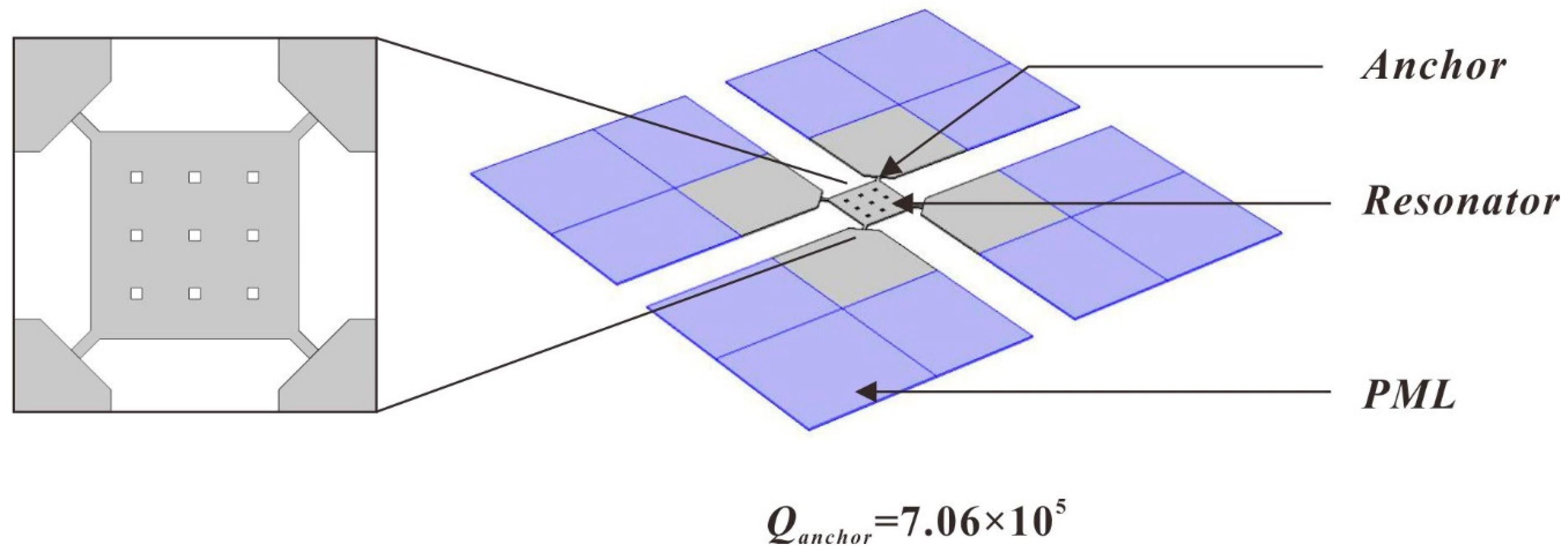
For the Lamé-mode resonator, the most important dissipation mechanisms include air damping, surface loss, thermo-elastic dissipation (TED), and anchor losses [28]. For resonators operating in atmosphere, air damping is the dominant dissipation. When operated in vacuum, the losses due to air damping can be significantly reduced. TED of the Lamé-mode resonator in very high frequency (VHF) and ultra high frequency (UHF) range is also low, since the volume of the structure is conserved during vibration [25]. Anchor loss is commonly understood to be determined by energy dissipation through the anchor point structure to the substrate when the resonator vibrates [29,30]. Optimizing the structure and size of the anchor beam can reduce the energy dissipation. Furthermore, the anchor loss can be simulated with the perfectly matched layer (PML) method [31] by building an efficient model of energy losses through the substrate in COMSOL, as shown in Figure 2. The anchor dimensions can be optimized to reduce the anchor loss, and the quality factor is extracted as 7.06 × 10⁵.
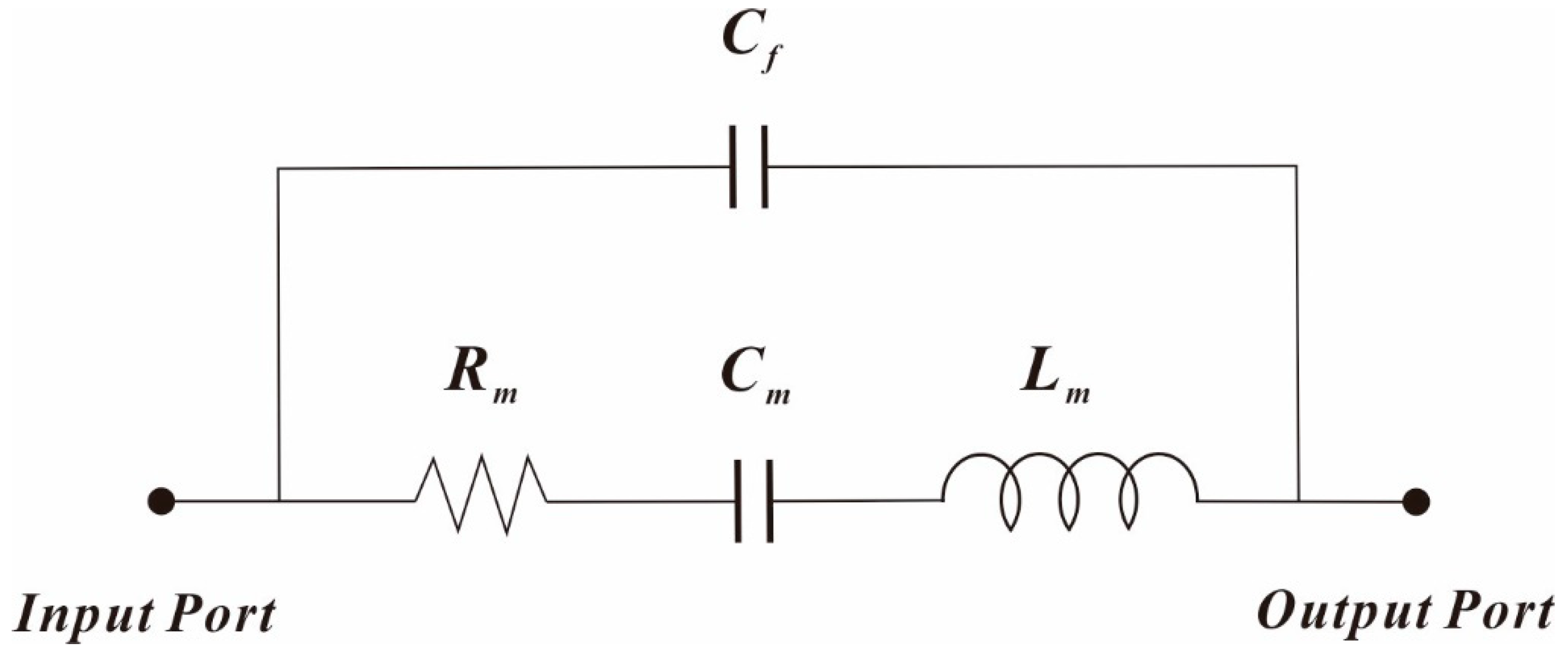
The small-signal equivalent electrical model of Lamé-mode resonator can be expressed using the Butterworth van Dyke (BVD) circuit model, as shown in Figure 3.
The motional resistance Rm, motional inductance Lm, motional capacitance Cm, and electromechanical coupling coefficient η for the Lamé-mode resonator can be expressed using the following equations [32]:
R m = k eff m eff Q η 2 , L m = m eff η 2 , C m = η 2 k eff
η = 2 ε 0 L h g 2 V DC
where ε0 is the permittivity, g is the spacing gap, and VDC is the bias voltage. Combining Equation (7) and Equation (8), the equivalent output electrical resistance of the resonator can be expressed by [33]:
R m = k eff m eff g 4 Q ε 0 2 L 2 h 2 V DC 2 g 4 Q
It can be seen that ultra-small capacitive gaps and high Q are required to reduce the equivalent motional resistance of the MEMS capacitive resonators.
For a parallel plate capacitor, the actuation force can be expressed by [24]:
F = 1 2 ( C x ) V 2
where V is the applied voltage, x is the displacement of resonator, C = ε0A/g is the capacitance of the parallel plate, and A is the transduction area, respectively. For a two-port configuration, the input voltage can be written as the sum of a DC bias VDC and an alternating current (AC) signal VAC = |VAC| cos(ωt) at resonant frequency, and the actuator force can be expressed as [20]:
F = V DC | V AC | ε 0 A g 2 cos ( ω 0 t ) = F 0 cos ( ω 0 t )
The motional current is given by [19]:
i m = V DC ( C x ) x ˙
and the maximum displacement at resonance can be expressed as [20]:
x max = F 0 Q m eff ω 0 2
Substituting Equation (10)–(12), the motional current can be expressed by [20]:
i m = | V DC 2 | | V AC | Q ε 0 2 A 2 m eff ω 0 g 4
It can be seen from Equation (14) that in the capacitive resonator, the sensing of mechanical vibration is limited by the transduction gap, transduction area, and Q factor. To reduce the bias voltage while maintaining strong sensing signal, a small gap, high Q factor, and large transduction area are needed.
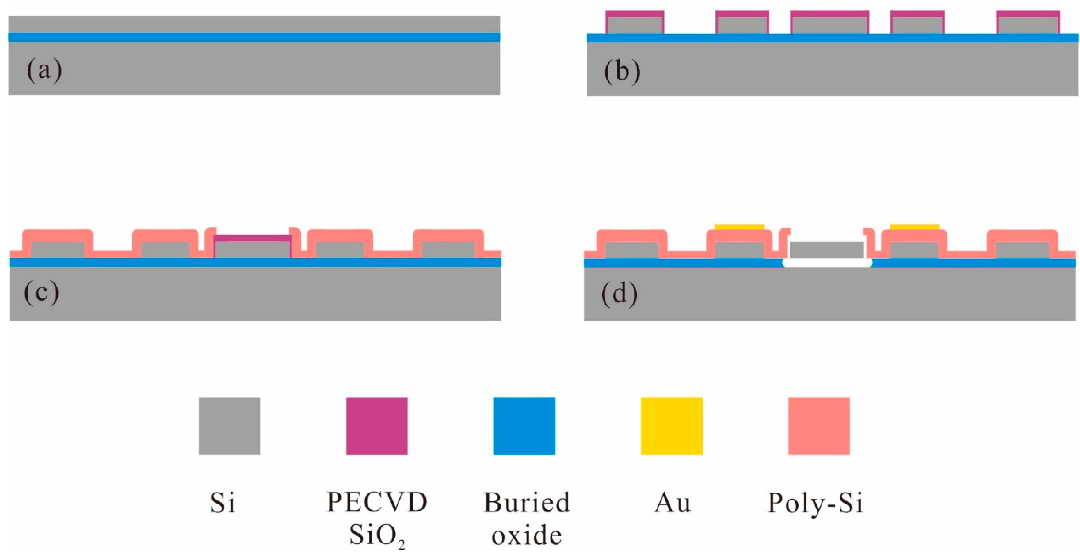
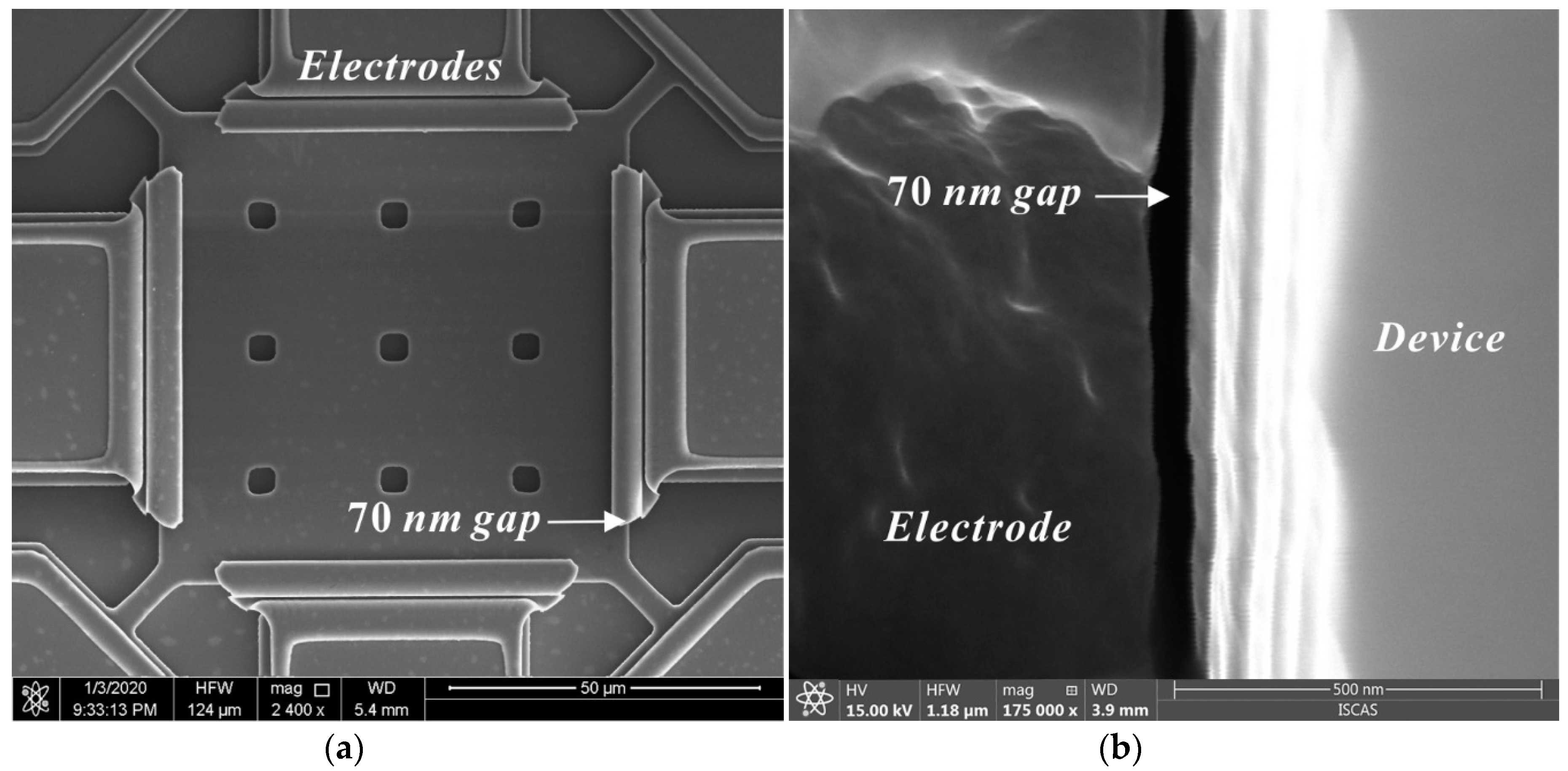
A simple and reliable fabrication process was developed, as illustrated in Figure 4. The silicon on insulator (SOI) wafer with a 2 µm-thick low-resistivity single-crystal-silicon (SCS) device layer, a 1 µm-thick oxide layer, and a 300 µm-thick silicon handling layer was employed to batch fabricate the proposed resonators; an approximately 1.2-µm-thick SiO2 layer is grown by plasma enhanced chemical vapor deposition (PECVD) as the dielectric layer and the hard mask for silicon etching. Then, the resonators are patterned by inductively coupled plasma (ICP) dry etch, and a 70 nm gap is defined by sacrificial thermal SiO2 layer. The grounding square hole arrays are fabricated by the ICP etching and filled with polysilicon—this can ensure extremely low feedthrough signal in the device. Subsequently, a 2 µm-thick heavily doped low pressure chemical vapor deposition (LPCVD) polysilicon is deposited and patterned to form the electrodes. The Au/Cr electrode pads are produced by e-beam evaporation and the lift-off process. Finally, the devices are released in a 49% concentrated HF solution. Figure 5 demonstrates the SEM images of the fabricated resonator.
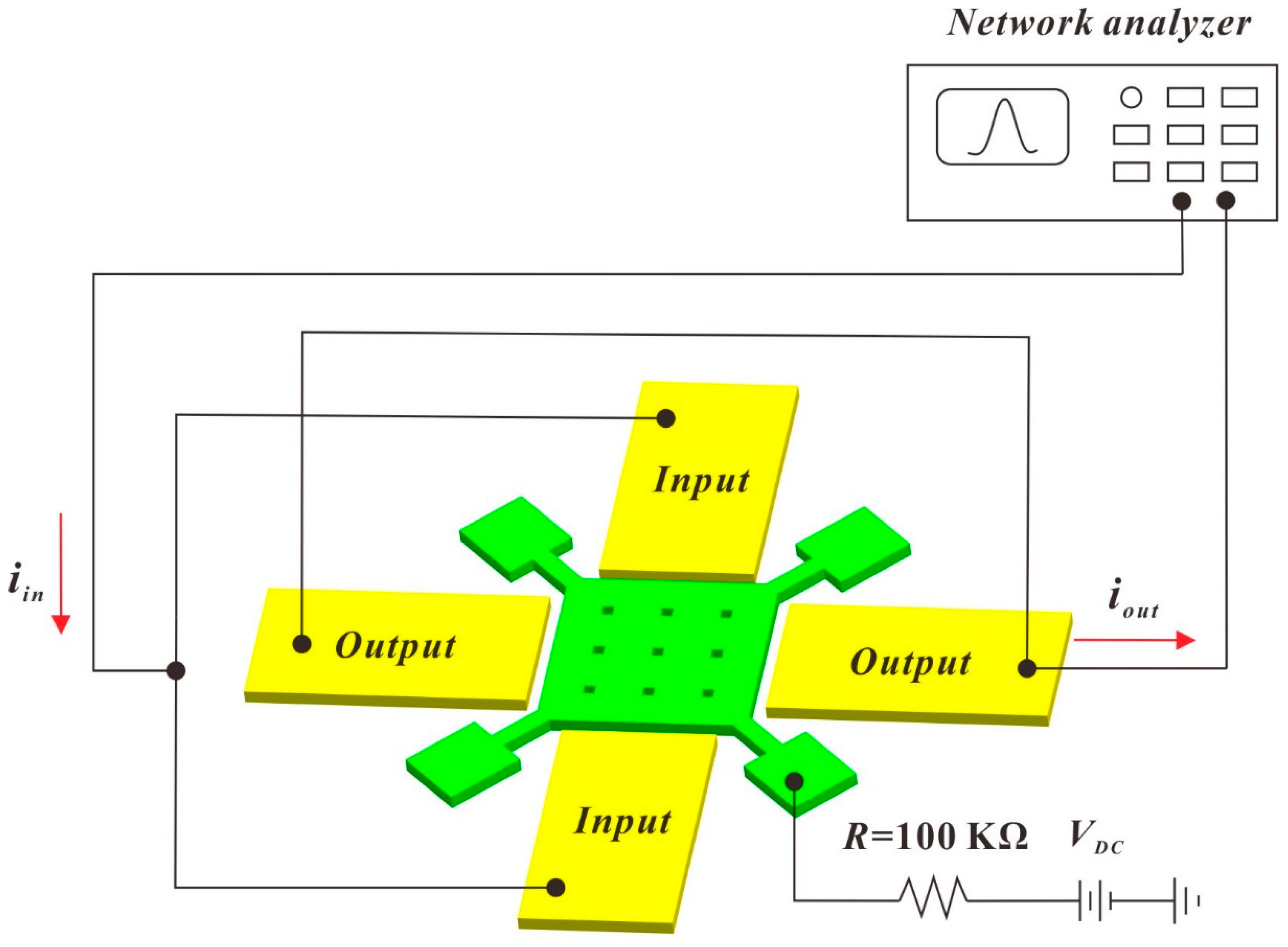
The frequency responses of the fabricated resonators are tested by the measurement setup shown in Figure 6. A radio frequency (RF) probe station was employed, a bias voltage VDC was directly applied to the resonator using the DC probe, and the substrate wafer was grounded to reduce the parasitic signal. A 0 dBm AC driving signal from the network analyzer was applied to the Cr/Au electrode pads using the AC probe of the RF probe station. A low pressure of 0.08 mbar was provided for measurement in vacuum.

3. Results and Discussions

The frequency responses of the fabricated Lamé-mode resonator operating in air and in vacuum are shown in Figure 7. The measured resonant frequency is around 51.3 MHz, which corresponds well with the calculated value from Equation (4). The resonator was driven into vibration at a low bias voltage of 3 V, and a high signal-to-noise ratio over 25 dB was obtained. The Lamé-mode resonator exhibits a Q value of 8150 in air and 34,200 in vacuum. The dramatic enhancement of Q values in vacuum indicates that the air damping is the dominant energy dissipation. The resonator can effectively suppress feedthrough, which is convenient for the extraction of resonance signals.
To better understand the effect of air damping on the Lamé-mode resonator, a finite element simulation based on squeezed film damping is conducted [34]. A Reynold’s equation is used to model the squeezed film between the resonator and electrodes [35]:
p a ( 2 ( δ p ) y 2 + 2 ( δ p ) z 2 ) 12 η eff g 2 ( δ p ) t = 12 η eff p a g 3 ( u ( y , t ) ) t
where pa is the ambient pressure, u(y,t) represents the deformations of the sidewalls, δp is the pressure changes inside the gap, and ηeff is the effective viscosity. y and z axes are defined along the length and thickness of the resonator. The boundary condition δp = 0 is applied to the top and bottom surfaces of the gap, since the pressure here is equal to ambient pressure [34]. At the side edges of the gap, the pressure gradient should be zero due to the anchors position:   δ p x = 0 [34]. Then, δp can be calculated with the boundary conditions described above, thus the energy loss Eair due to the squeezing film damping can be computed. The maximum stored energy Estore can be obtained by integrating the elastic potential energy over the resonator volume, the quality factor of the resonator due to the air damping can be estimated as follows:
Q = 2 π E store E air
The calculated Q factor due to air damping is 19,997 and 7.69 × 10⁷ at atmosphere and at a low pressure of 0.08 mbar, respectively, indicating that air damping dominates the resonant behavior of the resonator vibrating in air, and a vacuum package is needed for high-end resonators. In addition, the Q values measured at atmosphere and in vacuum are smaller than the simulated ones, indicating that there are other sources of energy loss.
The electrical parameters of the resonator can be estimated based on the insertion loss using the following equation [36]:
R m = 50 ( 10 I L dB 20 1 ) , L m = Q R m ω 0 , C m = 1 ω 0 Q R m
where ILdB is the insertion loss of the transmission and its unit is in decibels (dB). Table 2 summarizes the calculated and measured electrical parameters for the Lamé-mode resonators. The measured Rm of the Lamé-mode resonator with an applied bias VDC = 3 V in vacuum is 293.8 kΩ, which indicates that both the nano-scale air gap and high Q factor contributes to the reduced motional resistance.
For MEMS resonators, a nonlinear effect often occurs in the resonators with small stiffness, such as a beam resonator vibrating in the flexural mode [37]. For the bulk mode resonators with high-stiffness, such as the Lamé-mode resonator, nonlinear vibration seldom takes place. However, when a large driving force is applied, large vibration amplitude will cause frequency hysteresis [38].
For the resonator devices, the nonlinear effect is not desired in many applications. However, for some requirements, such as the MEMS oscillator, of which the power handling capabilities are limited by the small size of the MEMS resonator, it is usually necessary to drive the device into a nonlinear regime to achieve a sufficient signal-to-noise ratio and performance [39]. Therefore, an in-depth study on the nonlinearity of the resonator is important.
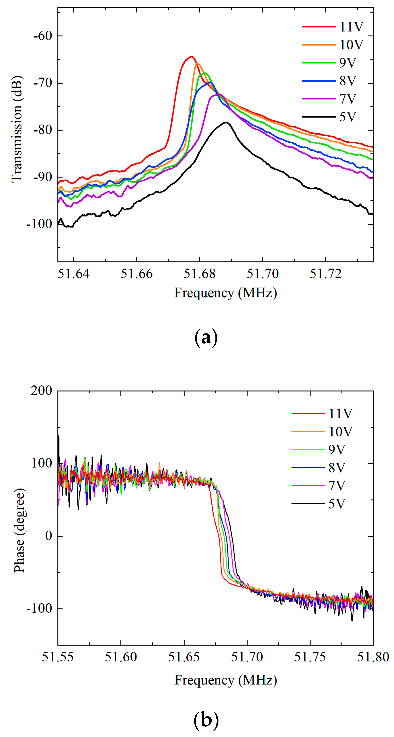
The frequency responses of the Lamé-mode resonator driven by different bias voltages are presented in Figure 8. When the driving voltage VDC is increased, the resonance frequency decreases due to the frequency tuning effect. The motional resistance and the Q factor are slightly improved. However, the effect of nonlinearity is prominent when the bias voltage VDC goes beyond 7 V.
In order to study the nonlinear effect, higher-order terms for the stiffness constant are introduced and the dynamic response of nonlinear vibration is [40]:
m eff 2 x t 2 + γ x t + k 1 x + k 2 x 2 + k 3 x 3 = F 0 cos ( ω 0 t )
where γ is the damping coefficient, k1, k2, and k3 are the equivalent linear, quadratic, and cubic spring constants, respectively. In symmetrical structures such as the Lamé-mode resonator presented in this work, k2 can be ignored [41]. The frequency change Δf due to the nonlinearity of the stiffness constant can be solved from Equation (18), and its approximate solution can be expressed by [42]:
Δ f = κ x max 2
where xmax is the amplitude of the resonator and κ is the coefficient associated with the nonlinear spring constant [42]:
κ = 3 k 3 8 k 1 f 0 5 k 2 2 12 k 1 2 f 0
It can be seen from Equation (19) that when the constant κ is positive, the nonlinearities cause the resonance peak to bend towards a higher frequency, and when the constant κ is negative, the resonance shifts to a lower frequency.
For electrostatic MEMS resonators, the equivalent stiffness is determined by both mechanical stiffness and electrostatic stiffness, so that the stiffness constants can be expressed by: k1 = k1m + k1e, k3 = k3m + k3e, where k1m, k1e represent the mechanical term and electrostatic term of linear stiffness constant, k3m, k3e represents the corresponding terms of the cubic stiffness constant. Electrostatic nonlinearities are caused by capacitive transduction, and often lead to a spring softening effect [43]. On the other hand, mechanical nonlinearities can be classified as two types: geometrical effects and material effects. For bulk mode resonators, material effects dominate the mechanical nonlinearities [44]. A nonlinear shear modulus is introduced:
G = G 0 + G 1 γ + G 2 γ 2
where G0, G1 and G2 are the linear, first and second order correction terms of shear modulus, respectively. The stiffness constants caused by material effects for the Lamé-mode resonator can be calculated using the following expression [45]:
k 1 m = π 2 G 0 h , k 2 m = 0 , k 3 m = 9 π 4 G 2 h 4 L 2
Furthermore, the linear mechanical spring constant k1m can be obtained from the experimental data. Ignoring the influence of the higher-order stiffness constant, the resonance frequency f0 and bias voltage VDC has the following relationship due to the electrical softening effect [45]:
f 0 = 1 2 π k 1 m k 1 e m eff = 1 2 π k 1 m V DC 2 ε 0 A total g 3 m eff
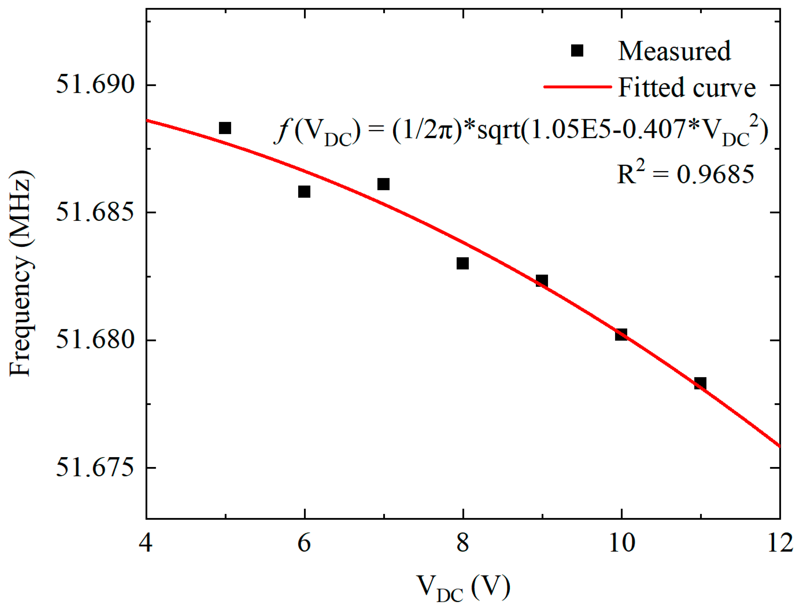
where Atotal is the total area of the resonator electrodes, and the effective mass can be obtained by Equation (3). By fitting the experimental data with Equation (23), the fitted linear mechanical stiffness constant k1m is 1.38 ×10⁶ N/m, coinciding with k1m calculated by Equation (22). The measured data and fitted curve for the frequency change versus the bias voltage VDC are presented in Figure 9.
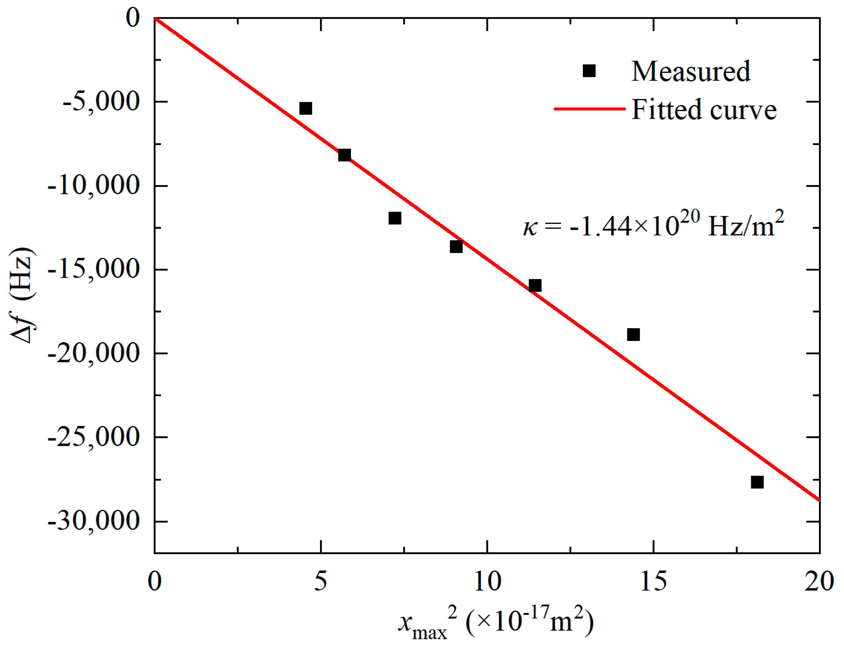
The cubic spring constant k3 cannot be experimentally measured, yet it is related to the coefficient κ by Equation (20). According to Equation (19), a linear fitting of Δf versus xmax2 measured with AC driving voltage range from −3 dBm to 3 dBm was performed with the bias voltage VDC = 10 V. The result is presented in Figure 10. The nonlinear parameter κ extracted was −1.44 × 10²⁰ Hz/m−2. Therefore, k3 can be calculated as −1.03 × 10¹⁹ N/m−3. For resonators with nano-scale gaps, since k3e is inversely proportional to g5 [43], the electrical nonlinearity should play a more important role than the mechanical nonlinearity and results in the spring soften exhibited by negative k3.
According to Equation (22), the nonlinear shear modulus G0 and G2 values of the Lamé-mode resonator can be extracted. Table 3 presents the comparison between extracted shear modulus and the reported ones.
In the oscillator application of MEMS resonator, nonlinearity will affect its power handling capability. For an ideal oscillator model, Leeson’s equation can be used to characterize the effect of nonlinearity on phase noise [46]:
L ( Δ f ) = 10 log ( k T Q π E stored f 0 + k T f 0 4 π E stored Q Δ f 2 )
where Lf) is the phase noise-to-carrier ratio, k is Boltzmann’s constant, T is the ambient temperature, Estored is the energy stored in the resonator. The second term in Equation (24) represents 1/f2 noise, which can be effectively reduced by increasing Estored and Q. For the Lamé-mode resonator described in this work, the bulk mode with high stiffness ensures a large stored energy and high Q factor.
Therefore, the impact of nonlinearity can be greatly reduced, and the high performance of the oscillator can be achieved.

4. Conclusions

A novel Lamé-mode square resonator was developed in this work. The Lamé-mode resonators have high Q factors: over 8000 in air and over 30,000 in vacuum. The high Q values, nano-scale gaps, and large electrode area greatly improve the capacitive transduction, and make it possible to drive the resonator into vibration at resonance frequency of 51.3 MHz with a voltage as low as 3 V. The nonlinearity of the Lamé-mode square resonator was studied, and the nonlinear parameters were extracted from the measured data to characterize. Such a high-Q resonator with low bias voltage has the potential to be utilized in building high-end MEMS oscillators and filters.

Author Contributions

T.W. conducted the theoretical analysis and wrote the manuscript; Z.C. conceived and conducted simulations; T.W. and Z.C. fabricated the devices, conceived and conducted experiments; Q.J. and Q.Y. validated and analyzed the experimental data; J.Y. conceived the study, analyzed results and theoretical background; F.Y. principal investigator, coordinated the experiments. All authors reviewed the manuscript. All authors have read and agreed to the published version of the manuscript.

Funding

This work was supported by the National Natural Science Foundation of China (61734007, 61874116 and 61804084), the National Key Research and Development Program of China (2017YFB0405400), the Key research program of Frontier Science of CAS (QYZDY-SSW-JSC004) and Youth Innovation Promotion Association, CAS(E07RQC03).

Conflicts of Interest

The authors declare no conflict of interest.

References

  1. Wang, J.; Yang, L.; Pietrangelo, S.; Ren, Z.; Nguyen, C.T.C. RF MEMS resonators: Getting the right frequency and Q. In Proceedings of the 2007 IEEE Compound Semiconductor Integrated Circuits Symposium, Portland, OR, USA, 14–17 October 2007; pp. 1–4. [Google Scholar]
  2. Iannacci, J. RF-MEMS technology: An enabling solution in the transition from 4G-LTE to 5G mobile applications. In Proceedings of the 2017 IEEE SENSORS, Glasgow, UK, 29 October–1 November 2017; pp. 1–3. [Google Scholar]
  3. Bahreyni, B. Fabrication & Design of Resonant Microdevices; William Andrew: Norwich, NY, USA, 2008. [Google Scholar]
  4. Ng, E.; Yang, Y.; Hong, V.A.; Ahn, C.H.; Heinz, D.B.; Flader, I.; Chen, Y.; Everhart, C.L.M.; Kim, B.; Melamud, R.; et al. The long path from MEMS resonators to timing products. In Proceedings of the 2015 28th IEEE International Conference on Micro Electro Mechanical Systems, Estoril, Portugal, 18–22 January 2015; pp. 1–2. [Google Scholar]
  5. Nguyen, C.T.C. MEMS technology for timing and frequency control. IEEE Trans. Ultrason. Ferroelectr. Freq. Control. 2007, 54, 251–270. [Google Scholar] [CrossRef] [PubMed] [Green Version]
  6. Kan, X.; Chen, Z.; Yuan, Q.; Wang, F.; Yang, J.; Yang, F. A Novel Multiple-Frequency RF-MEMS Resonator Based on the Whispering Gallery Modes. IEEE Trans. Electron. Devices 2019, 66, 3683–3685. [Google Scholar] [CrossRef]
  7. Yuan, Q.; Luo, W.; Zhao, H.; Peng, B.; Yang, J.; Yang, F. Frequency stability of RF-MEMS disk resonators. IEEE Trans. Electron. Devices 2015, 62, 1603–1608. [Google Scholar] [CrossRef]
  8. Nguyen, C.T.C. MEMS-based RF channel selection for true software-defined cognitive radio and low-power sensor communications. IEEE Commun. Mag. 2013, 51, 110–119. [Google Scholar] [CrossRef]
  9. Lin, Y.W.; Lee, S.; Li, S.S.; Xie, Y.; Ren, Z.; Nguyen, C.C. Series-resonant VHF micromechanical resonator reference oscillators. IEEE J. Solid -State Circuits 2004, 39, 2477–2491. [Google Scholar] [CrossRef]
  10. Khine, L.; Palaniapan, M.; Wong, W.K. 12.9 MHz Lamé-mode differential SOI bulk resonators. In Proceedings of the TRANSDUCERS 2007-2007 International Solid-State Sensors, Actuators and Microsystems Conference, Lyon, France, 10–14 June 2007; pp. 1753–1756. [Google Scholar]
  11. Khine, L.; Palaniapan, M.; Wong, W.K. 6MHz bulk-mode resonator with Q values exceeding one million. In Proceedings of the TRANSDUCERS 2007-2007 International Solid-State Sensors, Actuators and Microsystems Conference, Lyon, France, 10–14 June 2007; pp. 2445–2448. [Google Scholar]
  12. Pourkamali, S.; Hao, Z.; Ayazi, F. VHF single crystal silicon capacitive elliptic bulk-mode disk resonators-part II: Implementation and characterization. J. Microelectromechanical Syst. 2004, 13, 1054–1062. [Google Scholar] [CrossRef]
  13. Xereas, G.; Chodavarapu, V.P. Wafer-Level Vacuum-Encapsulated Lamé Mode Resonator With fQ Product of 2.23 × 10¹³ Hz. IEEE Electron. Device Lett. 2015, 36, 1079–1081. [Google Scholar] [CrossRef]
  14. Hamelin, B.; Yang, J.; Daruwalla, A.; Wen, H.; Ayazi, F. Monocrystalline Silicon Carbide Disk Resonators on Phononic Crystals with Ultra-Low Dissipation Bulk Acoustic Wave Modes. Sci. Rep. 2019, 9, 1–8. [Google Scholar]
  15. Yang, J.; Hamelin, B.; Ayazi, F. Capacitive Lamé Mode Resonators in 65 μm-Thick Monocrystalline Silicon Carbide with Q-Factors Exceeding 20 Million. In Proceedings of the 2020 IEEE 33rd International Conference on Micro Electro Mechanical Systems (MEMS), Vancouver, BC, Canada, 18–22 January 2020; pp. 226–229. [Google Scholar]
  16. Rodriguez, J.; Chandorkar, S.A.; Watson, C.A.; Glaze, G.M.; Ahn, C.H.; Ng, E.J.; Yang, Y.; Kenny, T.W. Direct detection of Akhiezer damping in a silicon MEMS resonator. Sci. Rep. 2019, 9, 1–10. [Google Scholar]
  17. Daruwalla, A.; Wen, H.; Liu, C.S.; Ayazi, F. Low motional impedance distributed lamé mode resonators for high frequency timing applications. Microsyst. Nanoeng. 2020, 6, 1–11. [Google Scholar] [CrossRef]
  18. Abele, N.; Segueni, K.; Boucart, K.; Casset, F.; Legrand, B.; Buchaillot, L.; Ancey, P.; Ionescu, A.M. Ultra-low voltage MEMS resonator based on RSG-MOSFET. In Proceedings of the 19th IEEE International Conference on Micro Electro Mechanical Systems, Istanbul, Turkey, 22–26 January 2006; pp. 882–885. [Google Scholar]
  19. Chen, T.T.; Huang, J.C.; Peng, Y.C.; Chu, C.-H.; Lin, C.-H.; Cheng, C.-W.; Li, C.-S.; Li, S.S. A 17.6-MHz 2.5 V ultra-low polarization voltage MEMS oscillator using an innovative high gain-bandwidth fully differential trans-impedance voltage amplifier. In Proceedings of the 2013 IEEE 26th International Conference on Micro Electro Mechanical Systems (MEMS), Taipei, Taiwan, 20–24 January 2013; pp. 741–744. [Google Scholar]
  20. Lin, A.T.; Lee, J.E.; Yan, J.; Seshia, A.A. Enhanced transduction methods for electrostatically driven MEMS resonators. In Proceedings of the TRANSDUCERS 2009-2009 International Solid-State Sensors, Actuators and Microsystems Conference, Denver, CO, USA, 21–25 June 2009; pp. 561–564. [Google Scholar]
  21. Li, S.S.; Lin, Y.W.; Xie, Y.; Ren, Z.; Nguyen, C.C. Micromechanical “hollow-disk” ring resonators. In Proceedings of the 17th IEEE International Conference on Micro Electro Mechanical Systems, Maastricht, The Netherlands, 25–29 January 2004; pp. 821–824. [Google Scholar]
  22. Abdelmoneum, M.A.; Demirci, M.U.; Nguyen, C.C. Stemless wine-glass-mode disk micromechanical resonators. In Proceedings of the Sixteenth Annual International Conference on Micro Electro Mechanical Systems, Kyoto, Japan, 23 January 2003; pp. 698–701. [Google Scholar]
  23. Hao, Z.; Ayazi, F. Support loss in micromechanical disk resonators. In Proceedings of the 18th IEEE International Conference on Micro Electro Mechanical Systems, Miami Beach, FL, USA, 30 January–3 February 2005; pp. 137–141. [Google Scholar]
  24. Abdolvand, R.; Bahreyni, B.; Lee, J.E.Y.; Nabki, F. Micromachined resonators: A review. Micromachines 2016, 7, 160. [Google Scholar] [CrossRef] [PubMed]
  25. Lee, J.E.; Yan, J.; Seshia, A.A. Low loss HF band SOI wine glass bulk mode capacitive square-plate resonator. J. Micromechanics Microengineering 2009, 19, 074003. [Google Scholar] [CrossRef]
  26. Lee, J.E.; Zhu, Y.; Seshia, A.A. A bulk acoustic mode single-crystal silicon microresonator with a high-quality factor. J. Micromechanics Microengineering 2008, 18, 064001. [Google Scholar] [CrossRef] [Green Version]
  27. Yasumura, K.Y.; Stowe, T.D.; Chow, E.M.; Pfafman, T.; Kenny, T.W.; Stipe, B.C.; Rugar, D. Quality factors in micron-and submicron-thick cantilevers. J. Microelectromechanical Syst. 2000, 9, 117–125. [Google Scholar] [CrossRef]
  28. Basu, J.; Bhattacharyya, T.K. Microelectromechanical resonators for radio frequency communication applications. Microsyst. Technol. 2011, 17, 1557. [Google Scholar] [CrossRef] [Green Version]
  29. Darvishian, A.; Shiari, B.; Cho, J.Y.; Nagourney, T.; Najafi, K. Anchor loss in hemispherical shell resonators. J. Microelectromechanical Syst. 2017, 26, 51–66. [Google Scholar] [CrossRef]
  30. Hao, Z.; Erbil, A.; Ayazi, F. An analytical model for support loss in micromachined beam resonators with in-plane flexural vibrations. Sens. Actuators A Phys. 2003, 109, 156–164. [Google Scholar] [CrossRef]
  31. Koyama, T.; Bindel, D.S.; He, W.; Quévy, E.P.; Govindjee, S.; Demmel, J.W.; Howe, R.T. Simulation tools for damping in high frequency resonators. In Proceedings of the SENSORS, Irvine, CA, USA, 30 October–3 November 2005; p. 4. [Google Scholar]
  32. Colinet, E.; Arcamone, J.; Niel, A.; Lorent, E.; Hentz, S.; Ollier, E. 100 MHz oscillator based on a low polarization voltage capacitive Lamé-mode MEMS resonator. In Proceedings of the 2010 IEEE International Frequency Control Symposium, Newport Beach, CA, USA, 1–4 June 2010; pp. 174–178. [Google Scholar]
  33. Pourkamali, S.; Ayazi, F. SOI-based HF and VHF single-crystal silicon resonators with sub-100 nanometer vertical capacitive gaps. In Proceedings of the TRANSDUCERS’03. 12th International Conference on Solid-State Sensors, Actuators and Microsystems, Boston, MA, USA, 8–12 June 2003; pp. 837–840. [Google Scholar]
  34. Hajhashemi, M.S.; Rasouli, A.; Bahreyni, B. Performance optimization of high order RF microresonators in the presence of squeezed film damping. Sens. Actuators A: Phys. 2014, 216, 266–276. [Google Scholar] [CrossRef]
  35. Nayfeh, A.H.; Younis, M.I. A new approach to the modeling and simulation of flexible microstructures under the effect of squeeze-film damping. J. Micromechanics Microengineering 2003, 14, 170. [Google Scholar] [CrossRef]
  36. Wang, J.; Ren, Z.; Nguyen, C.C. 1.156-GHz self-aligned vibrating micromechanical disk resonator. IEEE Trans. Ultrason. Ferroelectr. Freq. Control. 2004, 51, 1607–1628. [Google Scholar] [CrossRef]
  37. Shao, L.C.; Niu, T.; Palaniapan, M. Nonlinearities in a high-Q SOI Lamé-mode bulk resonator. J. Micromechanics Microengineering 2009, 19, 075002. [Google Scholar] [CrossRef]
  38. Luo, W.; Zhao, H.; Peng, B.H.; Zhao, J.C.; Yuan, Q.; Yang, J.L.; Yang, F.H. Nonlinearity characteristic of disk resonator. In Proceedings of the SENSORS, Valencia, Spain, 2–5 November 2014; pp. 918–921. [Google Scholar]
  39. Lee, H.K.; Melamud, R.; Chandorkar, S.; Salvia, J.; Yoneoka, S.; Kenny, T.W. Stable operation of MEMS oscillators far above the critical vibration amplitude in the nonlinear regime. J. Microelectromechanical Syst. 2011, 20, 1228–1230. [Google Scholar] [CrossRef]
  40. Rajai, P.; Khan, N.; Ahamed, M.J. Modeling of nonlinear oscillations of doped Lamé-mode MEMS silicon resonator. In Proceedings of the 2019 IEEE International Symposium on Inertial Sensors and Systems (INERTIAL), Naples, FL, USA, 1–5 April 2019; pp. 1–3. [Google Scholar]
  41. Veijola, T.; Mattila, T. Modeling of nonlinear micromechanical resonators and their simulation with the harmonic-balance method. Int. J. Rf Microw. Comput. -Aided Eng. 2001, 11, 310–321. [Google Scholar] [CrossRef]
  42. Landau, L.D.; Lifshitz, E.M. Mecahnis: Volume 1 of Course of Theoretical Physics, 3rd ed.; Butterworth-Heinemann: Boston, MA, USA, 1982; pp. 87–92. [Google Scholar]
  43. Kaajakari, V.; Mattila, T.; Oja, A.; Seppa, H.A.S.H. Nonlinear limits for single-crystal silicon microresonators. J. Microelectromechanical Syst. 2004, 13, 715–724. [Google Scholar] [CrossRef] [Green Version]
  44. Zhu, H.; Tu, C.; Lee, J.E.Y. (2012, March). Material nonlinearity limits on a Lamé-mode single crystal bulk resonator. In Proceedings of the 2012 7th IEEE International Conference on Nano/Micro Engineered and Molecular Systems (NEMS), Kyoto, Japan, 5–8 March 2012; pp. 457–462. [Google Scholar]
  45. Yang, Y.; Ng, E.J.; Hong, V.; Ahn, C.; Chen, Y.; Ahadi, E.; Dykman, M.; Kenny, T.W. Measurement of the nonlinear elasticity of doped bulk-mode MEMS resonators. In Proceedings of the Solid-State Sensors, Actuators, Microsystems Workshop, Hilton Head Island, SC, USA, 8–12 June 2014; pp. 8–12. [Google Scholar]
  46. Kaajakari, V.; Koskinen, J.K.; Mattila, T. Phase noise in capacitively coupled micromechanical oscillators. IEEE Trans. Ultrason. Ferroelectr. Freq. Control. 2005, 52, 2322–2331. [Google Scholar] [CrossRef]
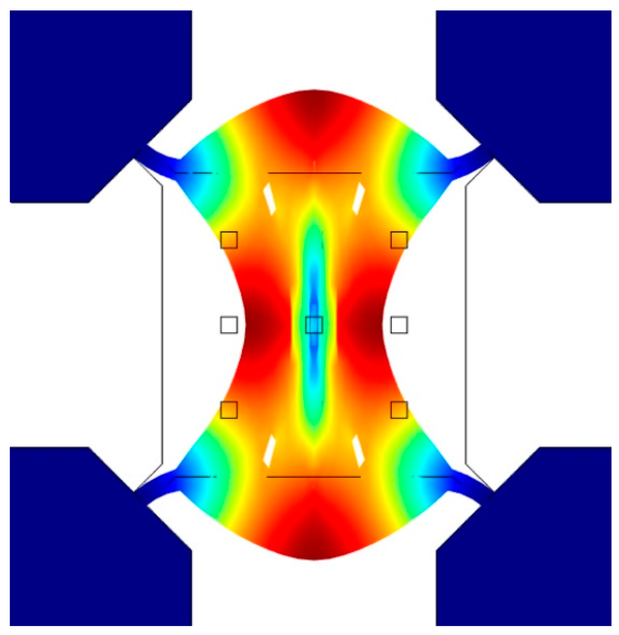
Figure 1. Simulated mode shapes of Lamé-mode resonator.
Micromachines 11 00737 g001
Figure 2. Simulation model of anchor loss using the perfectly matched layer (PML) method in COMSOL.
Micromachines 11 00737 g002
Figure 3. Small-signal equivalent electrical model of the Lamé-mode resonator.
Micromachines 11 00737 g003
Figure 4. Fabrication process for the Lamé-mode resonator.
Micromachines 11 00737 g004
Figure 5. SEM picture of the fabricated Lamé-mode resonator (a) and the cross-section of the capacitive 70 nm gaps (b).
Micromachines 11 00737 g005
Figure 6. Measurement setup for the Lamé-mode resonator.
Micromachines 11 00737 g006
Figure 7. Transmission characteristic curves of the Lamé-mode resonator measured in air (a) and in vacuum (0.08 mbar) (b).
Micromachines 11 00737 g007aMicromachines 11 00737 g007b
Figure 8. The frequency responses of Lamé-mode resonator operating in atmosphere under different bias voltage in transmission amplitude (a) and phase (b).
Micromachines 11 00737 g008
Figure 9. The fitted curve of frequency changes versus the bias voltage of Lamé-mode resonator.
Micromachines 11 00737 g009
Figure 10. Relationship between ∆f and xmax2 for the Lame-mode resonator.
Micromachines 11 00737 g010
Table 1. Comparison between state-of-the-art works and our Lamé mode resonator.
ReferenceResonatorf0QVDCF × QGap
Khine, L. [10]Lamé-mode12.9 MHz7.6 × 105100 V9.80 × 10122 μm
Xereas, G. [13]Lamé-mode6.89 MHz3.24 × 10640 V2.23 × 10131.5 μm
Rodriguez, J. [16]Lamé-mode10 MHz2.65 × 10630 V2.69 × 1013700 nm
Hamelin, B. [14]gyroscopic mode SiC disk5.3 MHz1.8 × 10725 V9 × 10134.2 μm
Pourkamali, S. [12]Wine-glass mode disk149.3 MHz45.70017 V6.82 × 1012100 nm
Yang, J. [15]SiC Lamé-mode6.27 MHz2.0 × 10715 V1.25 × 10145 μm
Daruwalla, A. [17]Distributed Lamé-mode50.7 MHz2.5 × 1055 V1.29 × 1013270 nm
Lin, A.T. [20]Lamé-mode2.2 MHz67713 V1.49 × 10102 μm
Chen, T.T. [19]Lamé-mode17.6 MHz80002.5 V1.41 × 101150 nm
Our workLamé-mode51.3 MHz34,2003 V1.75 × 101270 nm
Table 2. Calculated and measured electrical parameters of the Lamé-mode resonator.
ItemsRmLmCm
Measured293.8 kΩ31.2 H3.09 × 10−19 C
Calculated320.5 kΩ33.8 H2.81 × 10−19 C
Table 3. Comparison of the extracted nonlinear shear modulus G0 and G2.
ResonatorG0 (×1010 Pa)|G2| (×1011 Pa)
Zhu, H. [44]5.112.85
Shao, L. C. [37]8.731.85
Yang, Y. [45]4.628.76
Our work6.994.03