
Design, Simulation, Fabrication, and Characterization of an Electrothermal Tip-Tilt-Piston Large Angle Micromirror for High Fill Factor Segmented Optical Arrays

Abstract
:1. Introduction
2. Design and Methods
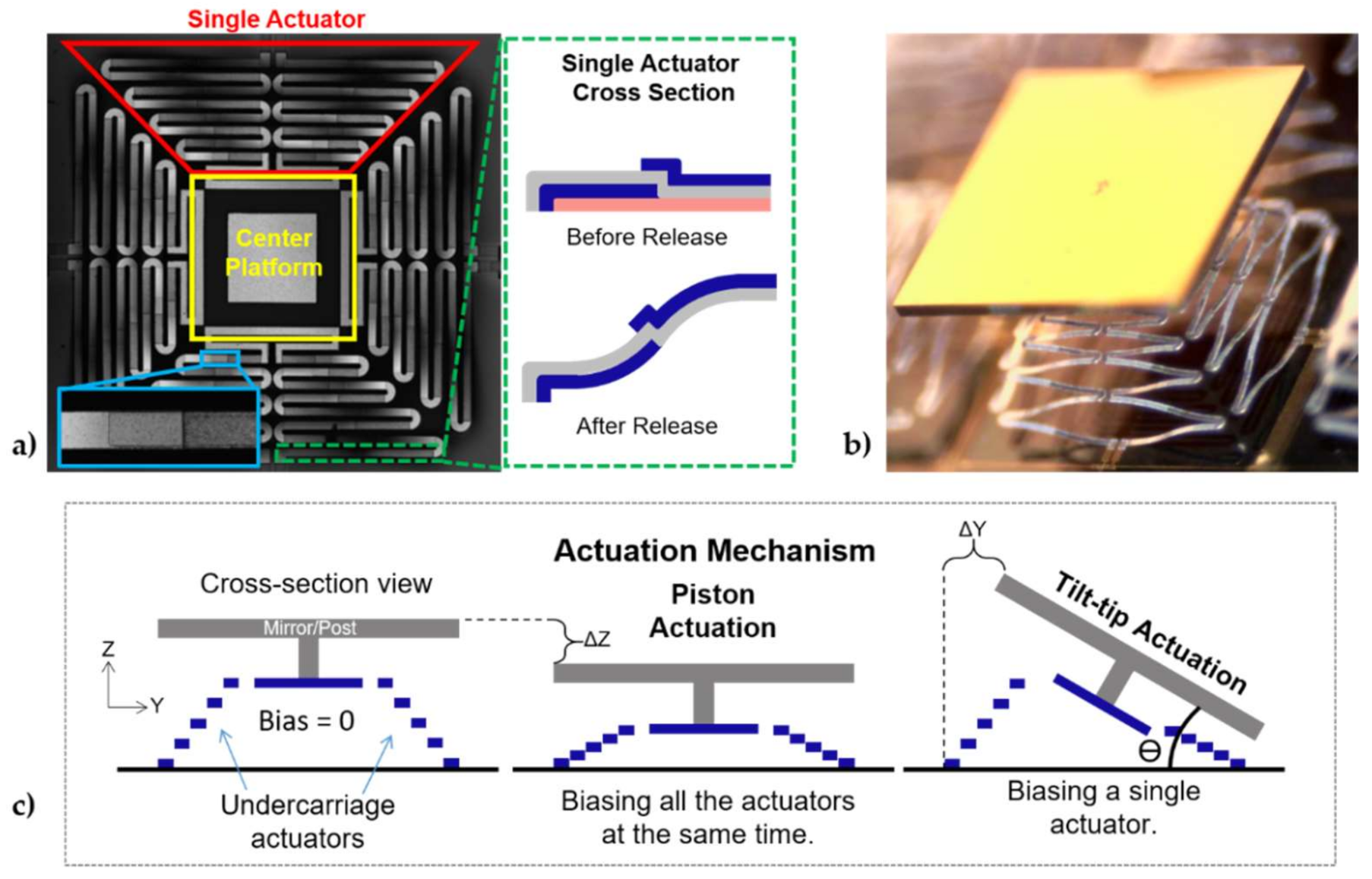
2.1. Design
2.2. Fabrication
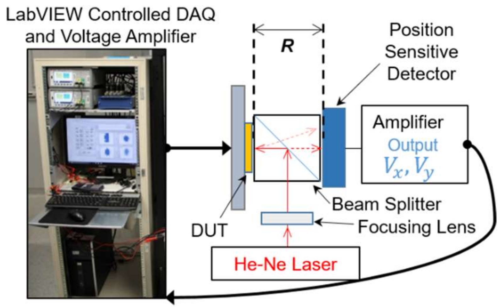
2.3. Experimental Setups
3. Results
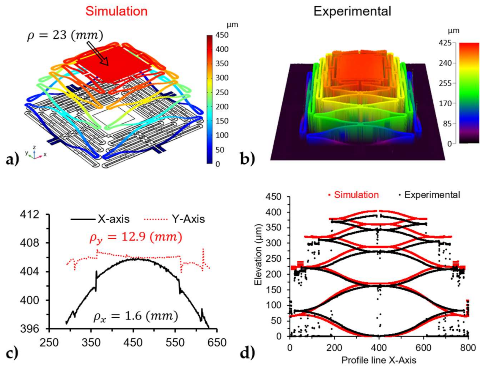
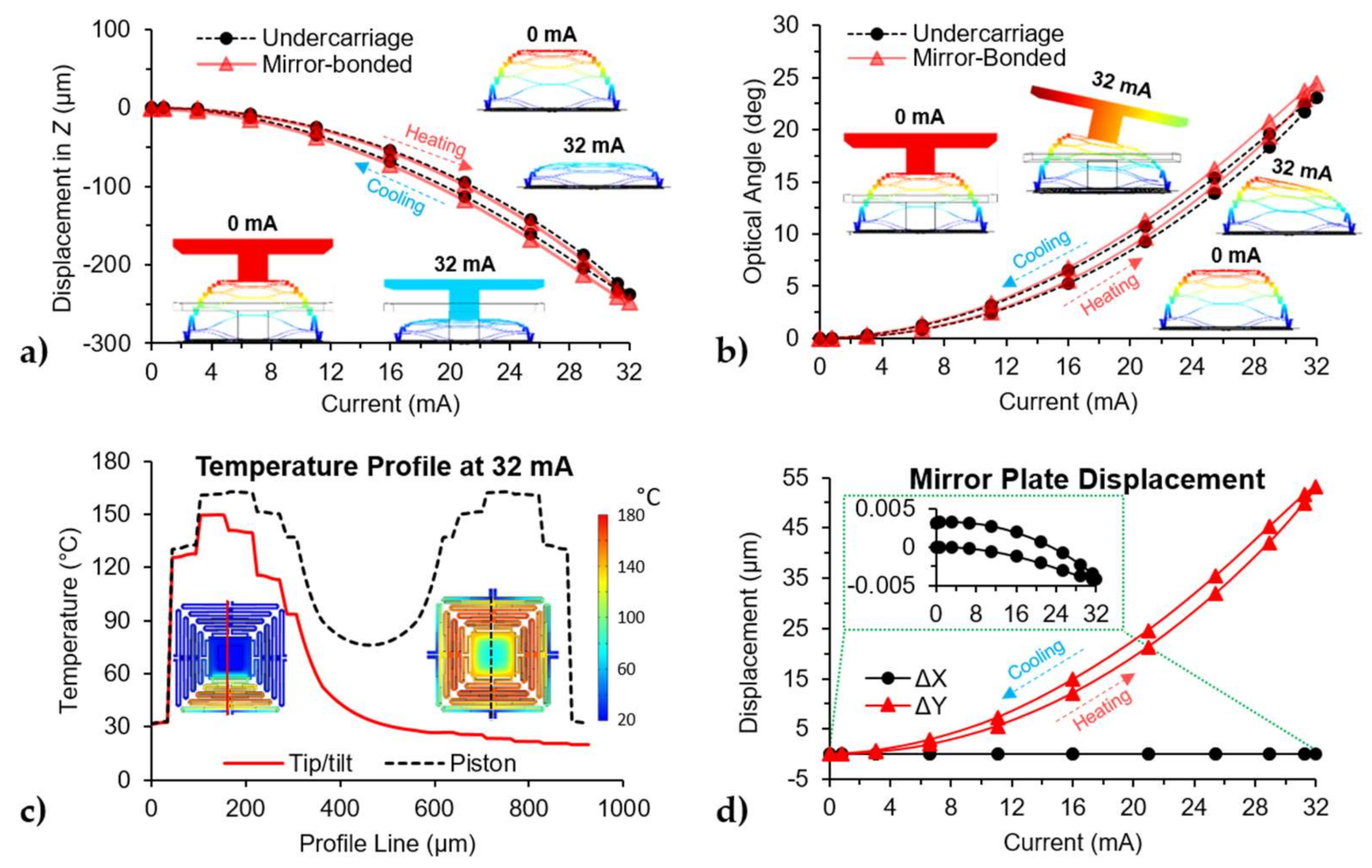
3.1. FEM Model
3.2. Characterization
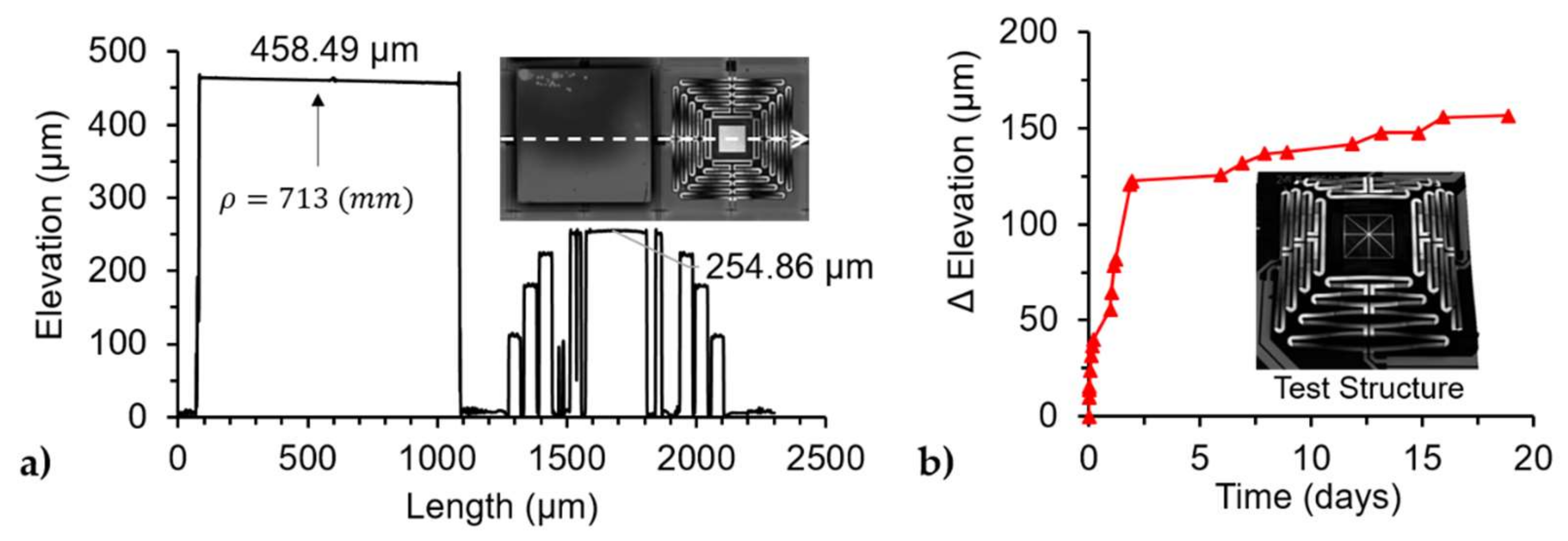
3.2.1. Release Characterization
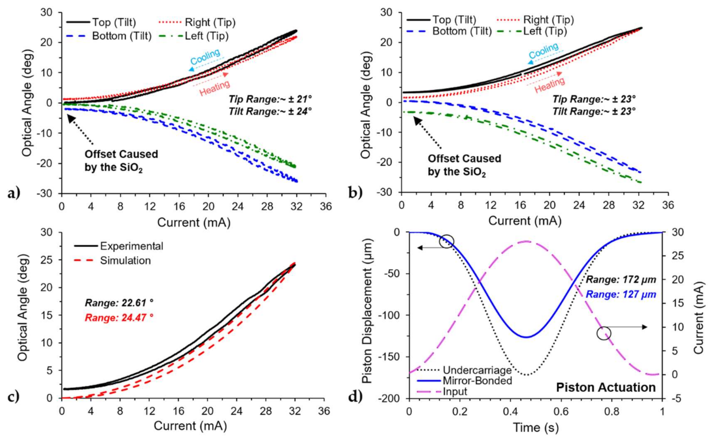
3.2.2. AC Steady-State
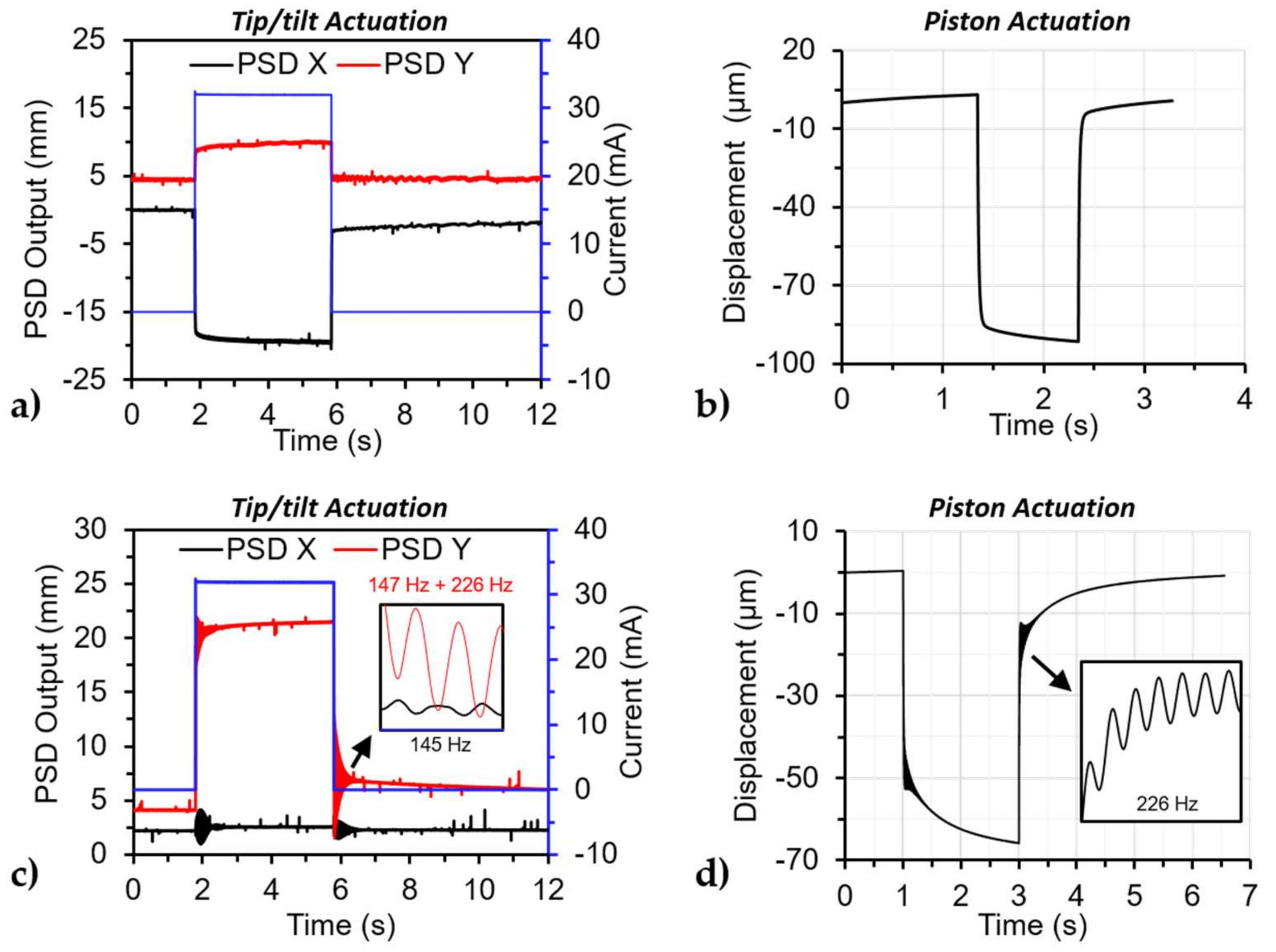
3.2.3. Transient Response
3.2.4. Frequency Response
4. Conclusions
Author Contributions
Funding
Acknowledgments
Conflicts of Interest
Appendix A

| SiO2 Deposition Conditions | |
|---|---|
| RF Power (W) | 25 |
| Pressure (mT) | 900 |
| SiHe (sccm) | 160 |
| N2O (sccm) | 900 |
| Chamber Temperature (degC) | 60 |
| Electrode Temperature (degC) | 200 |
| DC Bias (V) | 11 |
| Time (min:sec) | 15:20 |
| Film Thickness (nm) | 755.6 |
| Film index | 1.46 |
| Deposition Rate (Å/min) | 492.6 |
References
- Hornbeck, L.J. Digital light processing for high-brightness high-resolution applications. In Proceedings of the SPIE, Projection Displays III, San Jose, CA, USA, 8 May 1997; Volume 3013, pp. 27–40. [Google Scholar] [CrossRef]
- Boatright, K. TI DLP® Technology for Laser TV Displays (Rev. A). Texas Instrument White Paper 2018. Available online: https://www.ti.com/lit/wp/dlpc105a/dlpc105a.pdf?ts%20=1600178920557&ref_url=https%253A%252F%252Fwww.ti.com%252Ftool%252FTIDA-01474 (accessed on 6 January 2021).
- Bitte, F.; Dussler, G.; Pfeifer, T. 3D micro-inspection goes DMD. Opt. Lasers Eng. 2001, 36, 155–167. [Google Scholar] [CrossRef]
- Qiu, Z.; Piyawattanametha, W. MEMS-Based Medical Endomicroscopes. IEEE J. Sel. Top. Quantum Electron. 2015, 21, 376–391. [Google Scholar] [CrossRef]
- Pengwang, E.; Rabenorosoa, K.; Rakotondrabe, M.; Andreff, N. Scanning Micromirror Platform Based on MEMS Technology for Medical Application. Micromachines 2016, 7, 24. [Google Scholar] [CrossRef]
- Kasturi, A.; Milanovic, V.; Atwood, B.H.; Yang, J. UAV-borne lidar with MEMS mirror-based scanning capability. In Proceedings of the SPIE, Laser Radar Technology and Applications XXI, Baltimore, MD, USA, 13 May 2016; Volume 9832. [Google Scholar] [CrossRef]
- Wang, D.; Thomas, L.; Koppal, S.; Ding, Y.; Xie, H. A low-voltage, low-current, digital-driven MEMS mirror for low-power LiDAR. IEEE Sens. Lett. 2020, 4, 1–4. [Google Scholar] [CrossRef]
- Milanovic, V.; Kasturi, A.; Hachtel, V. High brightness MEMS mirror based head-up display (HUD) modules with wireless data streaming capability. In Proceedings of the SPIE, MOEMS and Miniaturized Systems XIV, San Francisco, CA, USA, 27 February 2015; Volume 9375, p. 93750A. [Google Scholar] [CrossRef]
- Hillmer, H.; Al-Qargholi, B.; Khan, M.M.; Worapattrakul, N.; Wilke, H.; Woidt, C.; Tatzel, A. Optical MEMS-based micromirror arrays for active light steering in smart windows. Jpn. J. Appl. Phys. 2018, 57, 8S2. [Google Scholar] [CrossRef]
- Glushko, B.; Shar, A.; Medina, M.; Kin, D.; Krylov, S. MEMS-based tracking for an indoor optical wireless communication bidirectional link. IEEE Photonics Technol. Lett. 2016, 28, 550–553. [Google Scholar] [CrossRef]
- Deng, P.; Kavehrad, M.; Lou, Y. MEMS-based beam-steerable FSO communications for reconfigurable wireless data center. In Proceedings of the SPIE, Broadband Access Communication Technologies XI, San Francisco, CA, USA, 28 January 2017; Volume 10128, p. 1012805. [Google Scholar] [CrossRef]
- Milanovic, V.; Matus, G.A.; McCormick, D.T. Gimbal-less monolithic silicon actuators for tip-tilt-piston micromirror applications. IEEE J. Sel. Top. Quantum Electron. 2004, 10, 462–471. [Google Scholar] [CrossRef] [Green Version]
- Torres, D.; Wang, T.; Zhang, J.; Zhang, X.; Dooley, S.; Tan, X.; Xie, H.; Sepúlveda, N. VO2-based MEMS mirrors. J. Microelectromec. Syst. 2016, 25, 780–787. [Google Scholar] [CrossRef]
- Song, Y.; Panas, R.M.; Hopkins, J.B. A review of micromirror arrays. Precis. Eng. 2018, 51, 729–761. [Google Scholar] [CrossRef]
- Takeshita, T.; Makimoto, N.; Nogami, H.; Sawada, R.; Kobayashi, T. Simulation and fabrication of a MEMS optical scanner device considering deformation caused by internal stress. Jpn. J. Appl. Phys. 2016, 55, 10TA11. [Google Scholar] [CrossRef] [Green Version]
- Lei, H.; Wen, Q.; Yu, F.; Zhou, Y.; Wen, Z. FR4-based electromagnetic scanning micromirror integrated with angle sensor. Micromachines 2018, 9, 214. [Google Scholar] [CrossRef] [Green Version]
- Gu-Stoppel, S.; Lisec, T.; Fichtner, S.; Funck, N.; Eisermann, C.; Lofink, F.; Wagner, B.; Müller-Groeling, A. A highly linear piezoelectric quasi-static MEMS mirror with mechanical tilt angles of larger than 10°. In Proceedings of the SPIE, MOEMS and Miniaturized Systems XVIII , San Francisco, CA, USA, 4 March 2019; Volume 10931, p. 1093102. [Google Scholar] [CrossRef]
- Dong, R.; Tan, Y.; Tan, Q. Mirror angle tuning of electromagnetic micro-mirrors with oscillation compensation. IEEE Trans. Syst. Manand Cybern. Syst. 2020, 50, 2969–2977. [Google Scholar] [CrossRef]
- Lei, H.; Wen, Q.; Yu, F.; Li, D.; Shang, Z.; Huang, J.; Wen, Z. AlN film based piezoelectric large-aperture MEMS scanning micromirror integrated with angle sensors. J. Micromech. Microeng. 2018, 28, 115012. [Google Scholar] [CrossRef]
- Ju, S.; Jeong, H.; Park, J.H.; Bu, J.U.; Ji, C.H. Electromagnetic 2D scanning micromirror for high definition laser projection displays. IEEE Photonics Technol. Lett. 2018, 30, 2072–2075. [Google Scholar] [CrossRef]
- Ozdogan, M.; Towfighian, S. Nonlinear dynamic behavior of a bi-axial torsional MEMS mirror with sidewall electrodes. Micromachines 2016, 7, 42. [Google Scholar] [CrossRef] [PubMed] [Green Version]
- Fan, C.; He, S. Micromirror based virtual image automotive head-up display. Microsyst. Technol. 2017, 23, 1671–1676. [Google Scholar] [CrossRef]
- Hopkins, J.B.; Panas, R.M.; Song, Y.; White, C.D. A High-Speed Large-Range Tip-Tilt-Piston Micromirror Array. J. Microelectromec. Syst. 2017, 26, 196–205. [Google Scholar] [CrossRef]
- Jia, K.; Pal, S.; Xie, H. An Electrothermal Tip–Tilt–Piston Micromirror Based on Folded Dual S-Shaped Bimorphs. J. Microelectromec. Syst. 2009, 18, 1004–1015. [Google Scholar] [CrossRef]
- Morrison, J.; Imboden, M.; Little, T.; Bishop, D. Electrothermally actuated tip-tilt-piston micromirror with integrated varifocal capability. Opt. Express 2015, 23, 9555–9566. [Google Scholar] [CrossRef] [PubMed]
- Lara-Castro, M.; Herrera-Amaya, A.; Escarola-Rosas, M.A.; Vázquez-Toledo, M.; López-Huerta, F.; Aguilera-Cortés, L.A.; Herrera-May, A.L. Design and Modeling of Polysilicon Electrothermal Actuators for a MEMS Mirror with Low Power Consumption. Micromachines 2017, 8, 203. [Google Scholar] [CrossRef] [PubMed] [Green Version]
- Merced, E.; Tan, X.; Sepúlveda, N. Strain energy density of VO2-based microactuators. Sens. Actuators A Phys. 2013, 196, 30–37. [Google Scholar] [CrossRef]
- Torres, D.; Zhang, J.; Dooley, S.; Tan, X.; Sepúlveda, N. Hysteresis-Based Mechanical State Programming of MEMS Mirrors. IEEE ASME J. Microelectromec. Syst. 2018, 27, 344–354. [Google Scholar] [CrossRef]
- Fu, Y.Q.; Luo, J.K.; Hu, M.; Du, H.J.; Flewitt, A.J.; Milne, W.I. Micromirror structure actuated by TiNi shape memory thin films. J. Micromech. Microeng. 2005, 15, 1872. [Google Scholar] [CrossRef]
- Gu-Stoppel, S.; Giese, T.; Quenzer, H.; Hofmann, U.; Benecke, W. PZT-Actuated and—Sensed Resonant Micromirrors with Large Scan Angles Applying Mechanical Leverage Amplification for Biaxial Scanning. Micromachines 2017, 8, 215. [Google Scholar] [CrossRef] [Green Version]
- Yang, S.; Xu, Q. A review on actuation and sensing techniques for MEMS-based microgrippers. J. Micro-Bio Robot. 2017, 13, 1–14. [Google Scholar] [CrossRef]
- Dochshanov, A.; Verotti, M.; Belfiore, N. A Comprehensive Survey on Microgrippers Design: Operational Strategy. J. Mech. Des. 2017, 139, 070801. [Google Scholar] [CrossRef]
- Jia, K.; Samuelson, S.R.; Xie, H. High-Fill-Factor Micromirror Array with Hidden Bimorph Actuators and Tip–Tilt-Piston Capability. J. Microelectromec. Syst. 2011, 20, 573–582. [Google Scholar] [CrossRef]
- Takeuchi, H.; Wung, A.; Sun, X.; Howe, R.T.; King, T.-J. Thermal budget limits ofquarter-micrometer foundry CMOS for post-processing MEMS devices. IEEE Trans. Electron Devices 2005, 52, 2081–2086. [Google Scholar] [CrossRef]
- Hall, H.J.; Green, A.; Dooley, S.; Schmidt, J.D.; Starman, L.A.; Langley, D.; Coutu, R.A., Jr. Mass reduction patterning of silicon-on-oxide–based micromirrors. J. Micro/Nanolithogr. MEMS MOEMS 2016, 15, 045501. [Google Scholar] [CrossRef] [Green Version]
- Torres, D.; Dooley, S.; Starman, L.A. Large Out-of-Plane Deflection MEMS Actuators for Optical Applications. Proceedings 2018, 2, 1072. [Google Scholar] [CrossRef] [Green Version]
- Dunn, M.L.; Zhang, Y.; Bright, V.M. Deformation and Structural Stability of Layered Plate Microstructures Subjected to Thermal Loading. J. Microelectromec. Syst. 2002, 11, 372–384. [Google Scholar] [CrossRef]
- Ceiler, M.F., Jr.; Kohl, P.A.; Bidstrup, S.A. Plasma-Enhanced Chemical Vapor Deposition of Silicon Dioxide Deposited at Low Temperatures. J. Electrochem. Soc. 1995, 142, 2067. [Google Scholar] [CrossRef]
- Haque, M.S.; Naseem, H.A.; Brown, W.D. Residual stress behavior of thin plasma-enhanced chemical vapor deposited silicon dioxide films as a function of storage time. J. Appl. Phys. 1997, 81, 3129. [Google Scholar] [CrossRef]
- Haque, M.S.; Naseem, H.A.; Brown, W.D. Post-deposition processing of low temperature PECVD silicon dioxide films for enhanced stress stability. Thin Solid Films 1997, 308–309, 68–73. [Google Scholar] [CrossRef]
- Wang, W.; Chen, Q.; Wang, D.; Zhou, L.; Xie, H. A bi-directional large-stroke electrothermal MEMS mirror with minimal thermal and temporal drift. In Proceedings of the 2017 IEEE 30th International Conference on Micro Electro Mechanical Systems (MEMS), Las Vegas, NV, USA, 22–26 January 2017; pp. 331–334. [Google Scholar] [CrossRef]
- Wang, P.; Liu, Y.; Wang, D.; Liu, H.; Liu, W.; Xie, H. Stability Study of an Electrothermally-Actuated MEMS Mirror with Al/SiO2 Bimorphs. Micromachines 2019, 10, 693. [Google Scholar] [CrossRef] [Green Version]
- Torteman, B.; Kessler, Y.; Liberzon, A.; Krylov, S. Micro-beam resonator parametrically excited by electro-thermal Joule’s heating and its use as a flow sensor. Nonlinear Dyn. 2019, 98, 3051–3065. [Google Scholar] [CrossRef]


| Material Layer | Thickness Expected [µm] | Thickness Measured (µm) |
|---|---|---|
| Bottom Silicon Dioxide | 1 | 1.02 |
| Metal (Al/Ti) | 1 | 1.19 |
| Top Silicon Dioxide | 1 | 0.64 |
| Material Properties | Materials | ||
|---|---|---|---|
| SiO2 | Al | Si | |
| Thickness (µm) | 1 | 1.2 | 0.6 |
| Coefficient of Thermal Expansion (CTE) (10−6 1/K) | 0.5 | 23.1 | 2.6 |
| Heat Capacity at Constant Pressure (J/(kg·K) | 730 | 904 | 678 |
| Density (kg/m3) | 2200 | 2700 | 2320 |
| Thermal Conductivity (W/m·K) | 1.4 | 237 | 34 |
| Young’s Modulus (GPa) | 70 | 70 | 160 |
| Poisson’s Ratio | 0.17 | 0.35 | 0.22 |
| Electrical Conductivity (GS/m) | N/A | 35.5 | N/A |
| Relative Permittivity | N/A | 10 | N/A |
| Biased Actuator | Undercarriage | Mirror-Bonded Device | |||
|---|---|---|---|---|---|
| Actuation Range | Actuation Range | ||||
| Tip Actuation 1 | Single Actuator | Tip | Tilt | Tip | Tilt |
| 23.11° | 0.00344° | 24.48° | 0.00655° | ||
| Piston Actuation | All | 238.46 µm | 247.57 µm | ||
| Motion | Biased Actuator | Undercarriage | Mirror-Bonded Device | |||
|---|---|---|---|---|---|---|
| Actuation Range 1 | Actuation Range 1 | Resonant Frequency (Hz) | ||||
| Tip | Tilt | Tip | Tilt | |||
| Tip/Tilt | Top | 3.08 | 24.34 | 1.47 | 21.75 | 145 ± 1 |
| Right | 20.83 | 4.93 | 22.61 | 0.33 | 147 ± 1 | |
| Bottom | 5.1 | 24.19 | 1.05 | 23.83 | 145 ± 1 | |
| Left | 21.03 | 3.57 | 23.6 | 2.86 | 147 ± 1 | |
| Piston 2 | All | 172 µm | 127 µm | 226 ± 1 | ||
| Cut-off Frequency 3 | 35 Hz | 51 Hz | ||||
Publisher’s Note: MDPI stays neutral with regard to jurisdictional claims in published maps and institutional affiliations. |
© 2021 by the authors. Licensee MDPI, Basel, Switzerland. This article is an open access article distributed under the terms and conditions of the Creative Commons Attribution (CC BY) license (https://creativecommons.org/licenses/by/4.0/).
Share and Cite
Torres, D.; Starman, L.; Hall, H.; Pastrana, J.; Dooley, S. Design, Simulation, Fabrication, and Characterization of an Electrothermal Tip-Tilt-Piston Large Angle Micromirror for High Fill Factor Segmented Optical Arrays. Micromachines 2021, 12, 419. https://doi.org/10.3390/mi12040419
Torres D, Starman L, Hall H, Pastrana J, Dooley S. Design, Simulation, Fabrication, and Characterization of an Electrothermal Tip-Tilt-Piston Large Angle Micromirror for High Fill Factor Segmented Optical Arrays. Micromachines. 2021; 12(4):419. https://doi.org/10.3390/mi12040419
Chicago/Turabian StyleTorres, David, LaVern Starman, Harris Hall, Juan Pastrana, and Sarah Dooley. 2021. "Design, Simulation, Fabrication, and Characterization of an Electrothermal Tip-Tilt-Piston Large Angle Micromirror for High Fill Factor Segmented Optical Arrays" Micromachines 12, no. 4: 419. https://doi.org/10.3390/mi12040419
APA StyleTorres, D., Starman, L., Hall, H., Pastrana, J., & Dooley, S. (2021). Design, Simulation, Fabrication, and Characterization of an Electrothermal Tip-Tilt-Piston Large Angle Micromirror for High Fill Factor Segmented Optical Arrays. Micromachines, 12(4), 419. https://doi.org/10.3390/mi12040419