
Sensor-Embedded Automatic Grasping Forceps for Precise Corneal Suture in Penetrating Keratoplasty


Abstract
:1. Introduction
2. Materials and Methods
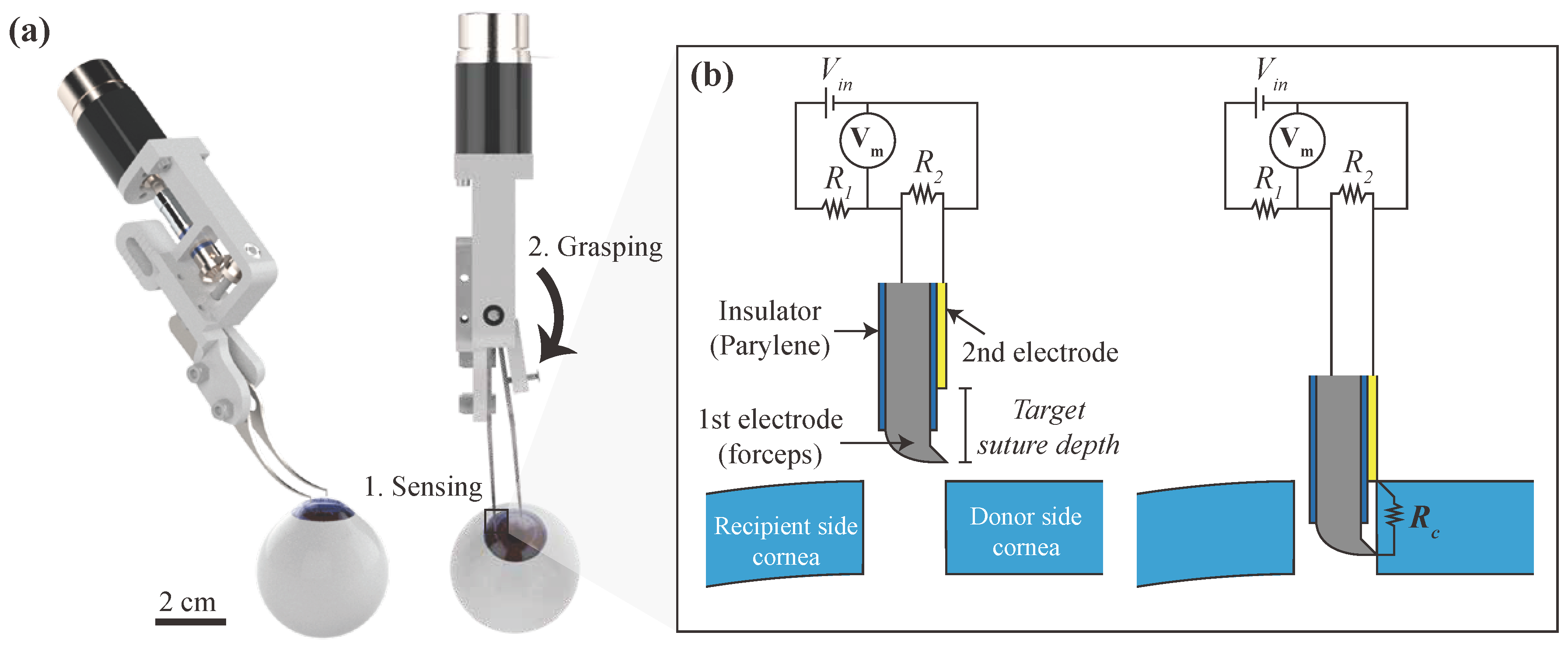
2.1. Automatic Grasping Mechanism
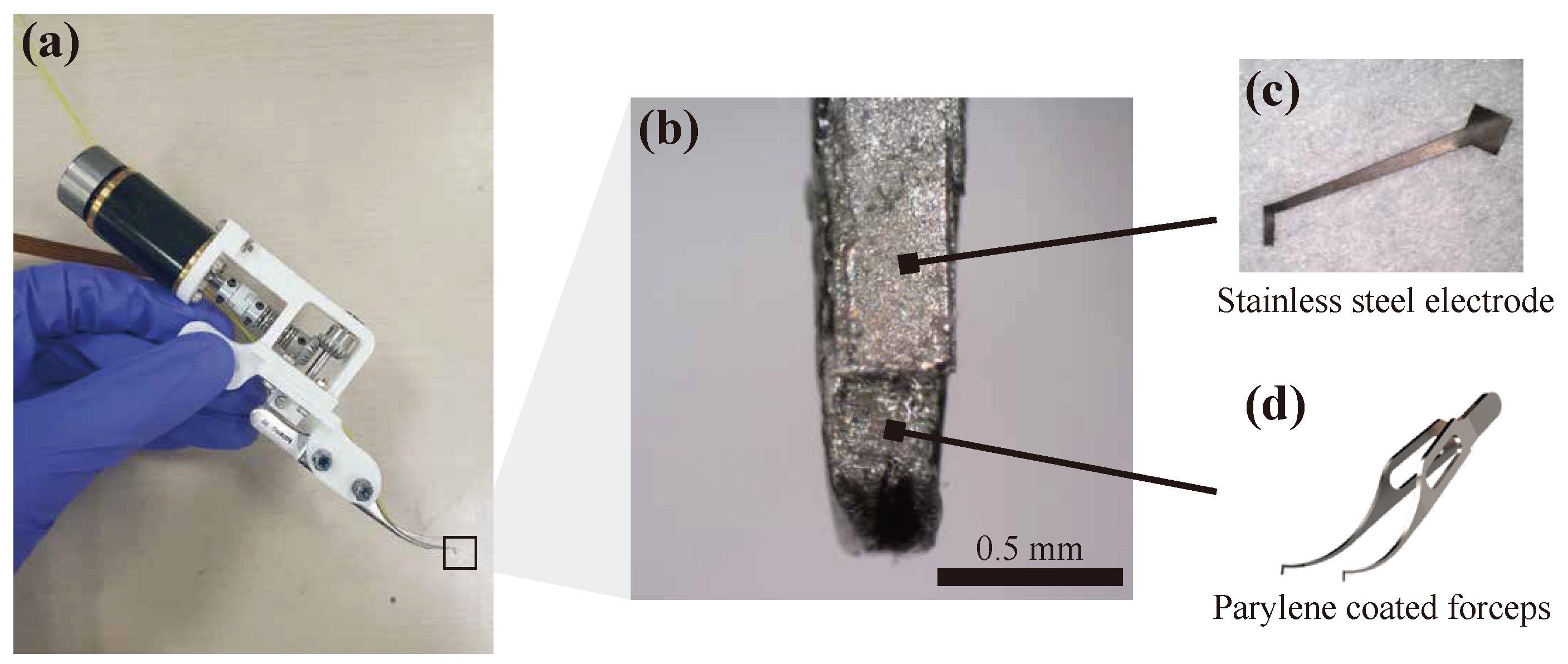
2.2. Sensor Fabrication
2.3. Actuation Part
2.4. Measurement Circuit
2.5. Preparation of Corneal Specimen
3. Results
3.1. Base Resistance and Resistance of Porcine Cornea
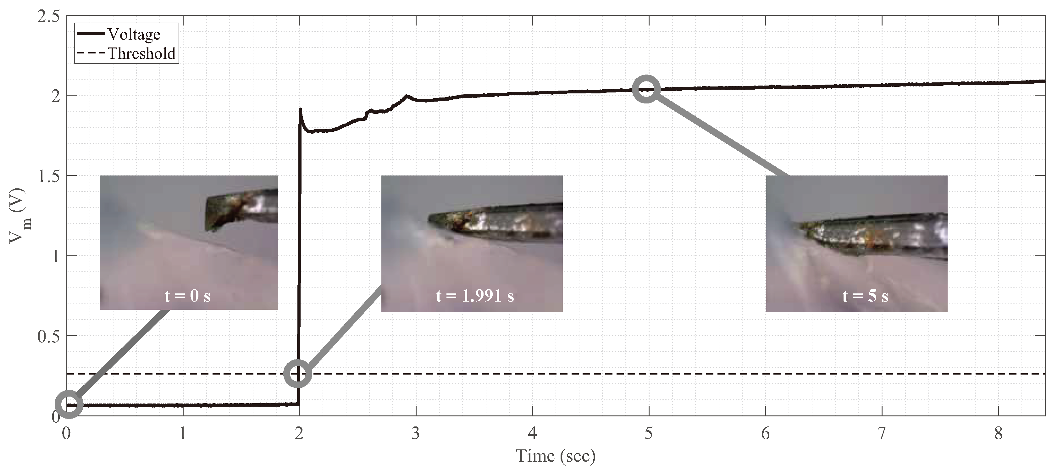
3.2. Sensor Signal While Linearly Moving Device’s Tip toward Corneal Tissue
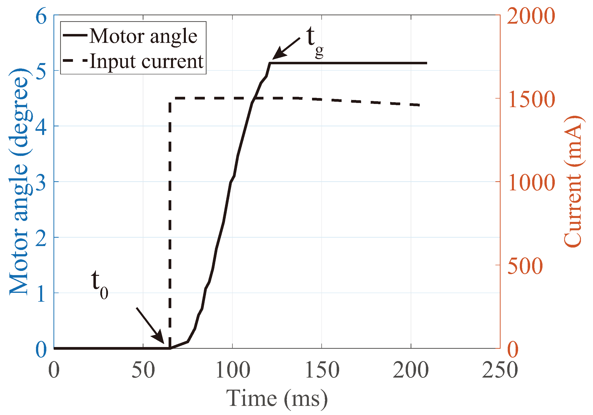
3.3. Measurement of Grasping Time
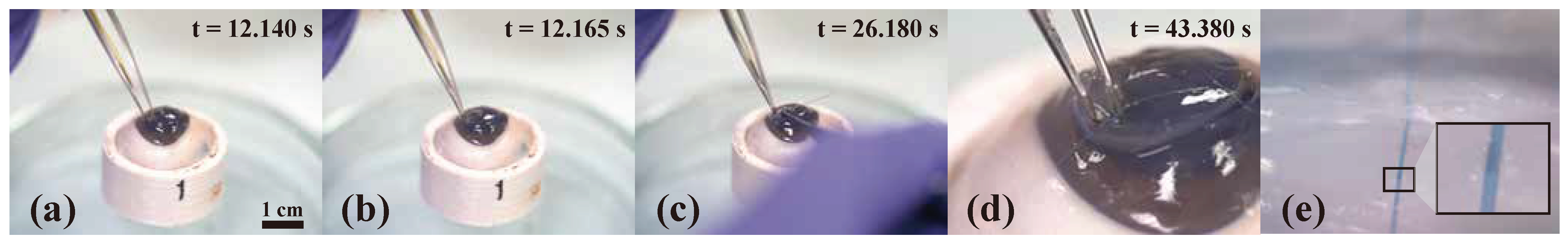
3.4. Suturing on Porcine Cornea
4. Discussion
Supplementary Materials
Author Contributions
Funding
Institutional Review Board Statement
Data Availability Statement
Conflicts of Interest
References
- Macsai, M.S. Ophthalmic Microsurgical Suturing Techniques; Springer: Berlin/Heidelberg, Germany, 2007. [Google Scholar]
- Hjortdal, J.; Søndergaard, A.; Fledelius, W.; Ehlers, N. Influence of suture regularity on corneal astigmatism after penetrating keratoplasty. Acta Ophthalmol. 2011, 89, 412–416. [Google Scholar] [CrossRef] [PubMed]
- Tuft, S.; Coster, D. The corneal endothelium. Eye 1990, 4, 389–424. [Google Scholar] [CrossRef] [PubMed]
- MacLachlan, R.A.; Becker, B.C.; Tabarés, J.C.; Podnar, G.W.; Lobes, L.A.; Riviere, C.N. Micron: An actively stabilized handheld tool for microsurgery. IEEE Trans. Robot. 2011, 28, 195–212. [Google Scholar] [CrossRef] [PubMed] [Green Version]
- Kanno, T.; Ito, N.; Kawashima, K. A cornea holding device for transplantation surgery using negative pressure. In Proceedings of the 2017 IEEE Conference on Control Technology and Applications (CCTA), Mauna Lani Bay Hotel, HI, USA, 27–30 August 2017; pp. 720–725. [Google Scholar]
- Park, I.; Kim, S.J.; Lee, D.; Kim, C.; Kim, M.J.; Chung, W.K. Design of Hand-held Suturing Device Integrated with Optical Coherence Tomography Probe for Corneal Suturing. In Proceedings of the 2018 IEEE International Conference on Cyborg and Bionic Systems (CBS), Shenzhen, China, 25–27 October 2018; pp. 270–273. [Google Scholar]
- Bourges, J.; Hubschman, J.; Burt, B.; Culjat, M.; Schwartz, S. Robotic microsurgery: Corneal transplantation. Br. J. Ophthalmol. 2009, 93, 1672–1675. [Google Scholar] [CrossRef] [PubMed]
- Chammas, J.; Sauer, A.; Pizzuto, J.; Pouthier, F.; Gaucher, D.; Marescaux, J.; Mutter, D.; Bourcier, T. Da Vinci Xi robot–assisted penetrating keratoplasty. Transl. Vis. Sci. Technol. 2017, 6, 21. [Google Scholar] [CrossRef] [PubMed] [Green Version]
- Yang, Y.; Deng, S.; Xiao, J.; Xu, C. Design and research of a corneal grafting robotic system. In Proceedings of the 2010 International Conference on Digital Manufacturing & Automation, Changsha, China, 18–20 December 2010; Volume 1, pp. 486–490. [Google Scholar]
- Yang, Y.; Xu, C.; Deng, S.; Xiao, J. Insertion force in manual and robotic corneal suturing. Int. J. Med. Robot. Comput. Assist. Surg. 2012, 8, 25–33. [Google Scholar] [CrossRef] [PubMed]
- Shin, H.G.; Park, I.; Kim, K.; Kim, H.K.; Chung, W.K. Corneal Suturing Robot Capable of Producing Sutures with Desired Shape for Corneal Transplantation Surgery. IEEE Trans. Robot. 2020, 37, 304–312. [Google Scholar] [CrossRef]
- Shin, H.G.; Park, I.; Chung, W.K. Insertion-depth sensor embedded automatic grasping forceps for precise cornea grasping in keratoplasty. In Proceedings of the 2018 IEEE International Conference on Cyborg and Bionic Systems (CBS), Shenzhen, China, 25–27 October 2018; pp. 266–269. [Google Scholar]
- Rodger, D.C.; Weiland, J.D.; Humayun, M.S.; Tai, Y.C. Scalable high lead-count parylene package for retinal prostheses. Sens. Actuators B Chem. 2006, 117, 107–114. [Google Scholar] [CrossRef]
- Yun, J.; Kim, H.W.; Lee, J.H. Improvement of depth profiling into biotissues using micro electrical impedance spectroscopy on a needle with selective passivation. Sensors 2016, 16, 2207. [Google Scholar] [CrossRef] [PubMed]
- Pasricha, N.D.; Haq, Z.; Ahmad, T.R.; Chan, L.; Redd, T.K.; Seitzman, G.D.; Parikh, N.; Kim, T.N.; Schallhorn, J.M.; Ramanathan, S. Remote corneal suturing wet lab: Microsurgical education during the COVID-19 pandemic. J. Cataract. Refract. Surg. 2020. [Google Scholar] [CrossRef] [PubMed]


| Ground to 1st Electrode | Ground to 2nd Electrode | Total (1st + 2nd Electrodes) |
|---|---|---|
| 6.7 | 3.5 | 10.2 |
| Resistance of Porcine Cornea (M) | |||||||||
|---|---|---|---|---|---|---|---|---|---|
| Eye 1 | Eye 2 | Eye 3 | Eye 4 | Eye 5 | Eye 6 | Eye 7 | Eye 8 | Mean | Std. |
| 3.7 | 5.8 | 13.8 | 5.3 | 6.4 | 5.5 | 36.3 | 36.3 | 14.1 | 13.1 |
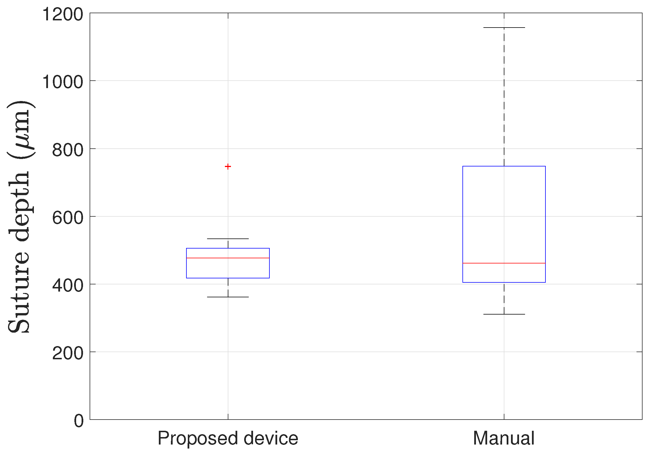
| Proposed Device | Manual | ||
|---|---|---|---|
| Mean (μm) | Std. (μm) | Mean (μm) | Std. (μm) |
| 447.1 | 85.8 | 573.3 | 221.6 |
Publisher’s Note: MDPI stays neutral with regard to jurisdictional claims in published maps and institutional affiliations. |
© 2021 by the authors. Licensee MDPI, Basel, Switzerland. This article is an open access article distributed under the terms and conditions of the Creative Commons Attribution (CC BY) license (https://creativecommons.org/licenses/by/4.0/).
Share and Cite
Shin, H.-G.; Park, I.; Kim, K.; Kim, H.-K.; Chung, W.-K. Sensor-Embedded Automatic Grasping Forceps for Precise Corneal Suture in Penetrating Keratoplasty. Micromachines 2021, 12, 484. https://doi.org/10.3390/mi12050484
Shin H-G, Park I, Kim K, Kim H-K, Chung W-K. Sensor-Embedded Automatic Grasping Forceps for Precise Corneal Suture in Penetrating Keratoplasty. Micromachines. 2021; 12(5):484. https://doi.org/10.3390/mi12050484
Chicago/Turabian StyleShin, Hyung-Gon, Ikjong Park, Keehoon Kim, Hong-Kyun Kim, and Wan-Kyun Chung. 2021. "Sensor-Embedded Automatic Grasping Forceps for Precise Corneal Suture in Penetrating Keratoplasty" Micromachines 12, no. 5: 484. https://doi.org/10.3390/mi12050484