Article

PI Film Laser Micro-Cutting for Quantitative Manufacturing of Contact Spacer in Flexible Tactile Sensor

1
State Key Lab of Digital Manufacturing Equipment and Technology, Huazhong University of Science and Technology, Wuhan 430070, China
2
School of Mechanical Science and Engineering, Huazhong University of Science and Technology, Wuhan 430070, China
*
Authors to whom correspondence should be addressed.
Micromachines 2021, 12(8), 908; https://doi.org/10.3390/mi12080908
Submission received: 30 May 2021 / Revised: 27 July 2021 / Accepted: 28 July 2021 / Published: 30 July 2021

Abstract

:
The contact spacer is the core component of flexible tactile sensors, and the performance of this sensor can be adjusted by adjusting contact spacer micro-hole size. At present, the contact spacer was mainly prepared by non-quantifiable processing technology (electrospinning, etc.), which directly leads to unstable performance of tactile sensors. In this paper, ultrathin polyimide (PI) contact spacer was fabricated using nanosecond ultraviolet (UV) laser. The quality evaluation system of laser micro-cutting was established based on roundness, diameter and heat affected zone (HAZ) of the micro-hole. Taking a three factors, five levels orthogonal experiment, the optimum laser cutting process was obtained (pulse repetition frequency 190 kHz, cutting speed 40 mm/s, and RNC 3). With the optimal process parameters, the minimum diameter was 24.3 ± 2.3 μm, and the minimum HAZ was 1.8 ± 1.1 μm. By analyzing the interaction process between nanosecond UV laser and PI film, the heating-carbonization mechanism was determined, and the influence of process parameters on the quality of micro-hole was discussed in detail in combination with this mechanism. It provides a new approach for the quantitative industrial fabrication of contact spacers in tactile sensors.

1. Introduction

Flexible tactile sensors are widely used in electronic skin [1,2,3], robots [4,5,6], wearable devices [7,8,9], etc. Depending on the source of the signal, the tactile sensors are classified into capacitive-type [10,11], piezoelectric-type [12,13], triboelectric-type [14] and piezoresistive-type [15,16,17,18]. Among them, the piezoresistive tactile sensor has been extensively studied for its advantages of simple structure, low manufacturing cost and convenient signal processing. As one of the core components in piezoresistive tactile sensors, a contact spacer acts as a regulator of sensitivity and test range. For instance, a 2 μm thick rigid SiO2 layer was applied as contact spacer and the sensor achieved ultra-high sensitivity of about 100–970 μA/kPa, but inflexibility limits its use scope [19]. In addition, a polyvinyl pyrrolidone (PVP) nanowire mesh was used to isolate the silver-plated micro-pyramids, creating a tactile sensor with an ultra-high sensitivity and ultra-wide detection range [20]. A tactile sensor with adjustable sensitivity and test range was fabricated by isolating the wrinkled polypyrrole (PVP) film through a polyvinyl alcohol (PVA) nanowire mesh [21]. However, the insulating nanowire mesh prepared by electrospinning process not only cannot quantify the size of single micro-hole, but also cannot uniformize the size of multiple micro-holes. The quantitative manufacturing of contact spacers thus should meet the following conditions: (1) flexible insulating film to isolate resistance, (2) ultra-thin film (1–10 μm) to form micro-sized peak in the micro-hole during compression deformation and (3) 5–100 μm diameter micro-hole can be fabricated quantitatively to form large contact resistance in a single micro-hole during compression deformation.
Polyimide (PI) film has many excellent properties such as flexibility, ultra-thin manufacturing (≥3 μm), insulation, high temperature resistance, radiation-resistance, etc., making it an excellent raw material for contact spacers. Ultra-thin PI film thus can be used to fabricate the contact spacer, and traditional machining methods such as stamping cannot fabricate micro-holes in the film. Laser-based micro-nano manufacturing has been widely used in various industries, such as metal organic framework (MOF) additive manufacturing [22], polydimethylsiloxane (PDMS) laser cutting in flexible electronics, laser direct writing for interdigitated electrode [23,24], laser induced biodegradation [25,26,27], etc. [28], laser micro-cutting thus may be a better method for preparing micro-holes through PI films. Nanosecond lasers are widely used in industrial production due to their low cost and high stability [29,30]. Ultraviolet (UV, 355 nm) laser has lower thermal ablation effect on the substrate than other wavelengths of light, so it is more suitable for manufacturing of organic materials to obtain smaller heat affected zones (HAZs) [31]. However, whether the interaction mechanism between the PI film and the UV nanosecond laser is a photothermal process or photochemical process, or both, remains to be further investigated [32,33,34]. In addition, the mechanism of PI film decomposition under laser irradiation conditions is still unclear, and the relationship between the thermal damage and the process parameters needs to be further investigated.
In this paper, nanosecond UV laser was chosen to fabricate the ultra-thin micro-hole PI film contact spacer. However, the evaluation index of micro-holes quality, the influence of process parameters on the evaluation index, and the interaction mechanism between UV laser and PI films are yet to be investigated. Firstly, an evaluation system of micro-hole based on roundness, diameter and size of the heat affected zone (HAZ) was established by analyzing the morphology after the laser micro-cutting. Secondly, the influence of process parameters was investigated by a 3-factor, 5-level orthogonal experiment to obtain the optimal process parameters. Finally, the interaction mechanism based on heating-carbonization was confirmed through the analysis of the products after laser micro-cutting and used to analyze the influence of process parameters. It provides a new approach for the quantitative industrial fabrication of contact spacers in tactile sensors.

2. Experiment Description

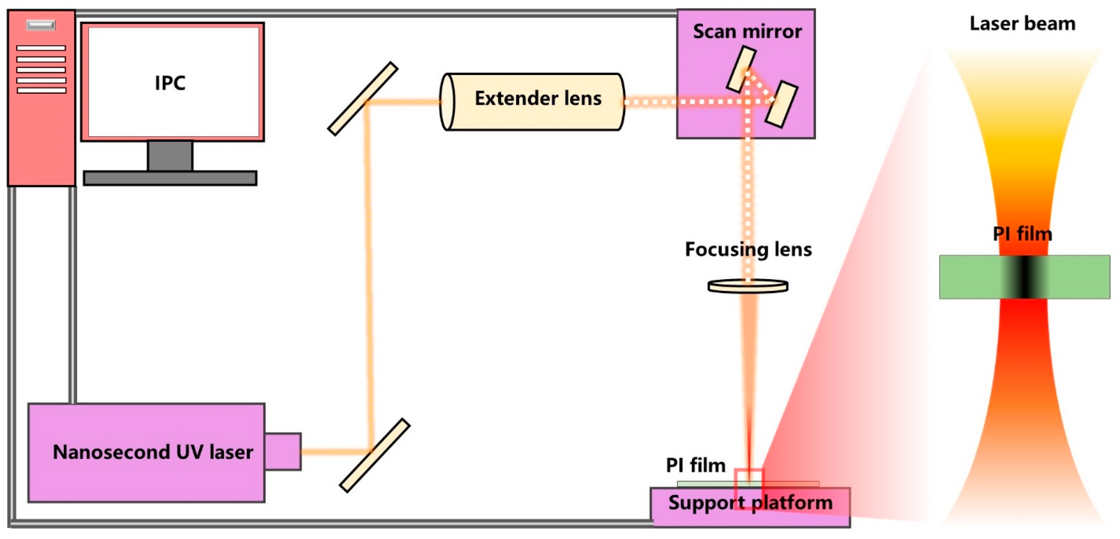
2.1. Laser Cutting System

As shown in Figure 1, the laser cutting system consisted of an industrial personal computer (IPC), nanosecond UV laser, extender lens, scan mirror, focusing lens and support platform. The nanosecond UV laser (Poplar-355-15A5, Huaray Precision Laser, Wuhan, China) had a maximum power of 12 W and pulse width < 15 ns. The extender lens was used to reduce laser processing power, because the diameter of laser spot expanded by the expander lens was larger than the entrance diameter of the scan mirror. The scan mirror (S10-355-D, SCANLAB, Pulheim, Germany) was used to control laser cutting path. The focusing lens (LINOS4401-402-000-20, QIOPTIQ, Gottingen, Germany) used in this study had a focal length of 167 mm. The 5 μm ultra-thin PI film (Taobao online store) was pasted on a piece of stainless steel, which was fixed on a motion platform. Output power of laser can be adjusted by setting pulse repetition frequency (PRF) values, and the correspondent relationship is shown in Table 1, where the power values are measured by power meter. After the laser processing, each sample was ultrasonically cleaned in deionized water and ethanol solution for 10 min in sequence, and then dried at room temperature.

2.2. Experiment Design of Laser Cutting Micro-Holes

According to previous experiments, the quality of micro-hole is mainly determined by the following three process parameters: PRF, cutting speed (CS) and repetition number of cuts (RNC). The nanosecond UV laser’s PRF could be varied from 50 to 200 kHz, the CS could be varied from 0.1 to 10,000 mm/s, and the RNC could be increased indefinitely. Higher cutting powers, slower cutting speeds and more RNC help to remove material but can also lead to more defects such as large HAZ. Therefore, based on preliminary test results, the specific PRF value varied from 160 to 200 kHz, the CS value varied from 10 to 50 mm/s, and the RNC value varied from 1 to 5. Furthermore, each parameter was set to 5 arithmetic values within the range of variation, and their influences on the micro-cutting quality was evaluated through orthogonal experiment of 3 factors and 5 levels. The values and levels of the main process parameters are shown in Table 2, and the specific process parameters are shown in Table 3.

2.3. Characterization

The basic morphology of the micro-hole was observed by a laser scanning confocal microscope (TCS SP8 X, Leica, Weztlar, Germany). In addition, a field emission scanning electron microscope (FS-EM, FEI Sirion 200, Santa Clara, CA, USA) was used to observe more detailed morphology and component analysis. The Raman spectra were carried out on a Raman spectrometer (HORIBA Jobin Yvon, Paris, France) with a 30 mW He-Cd laser of 532 nm. The thermogravimetric analysis (TGA) and differential thermal analysis (DTA) were measured by synchronous thermal analyzer (STA PT1600, LINSEIS, Zerb, Germany), that was carried out under air flow from room temperature to 800 °C at 10 min−1.

3. Results and Discussion

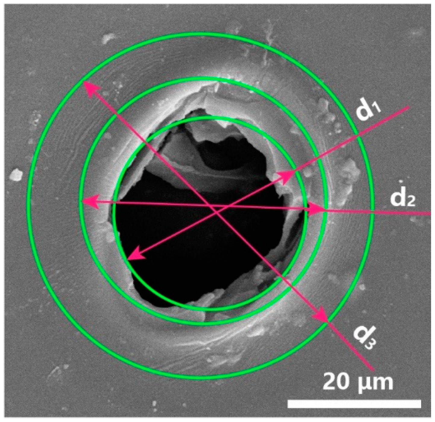
3.1. Quality Evaluation System of Laser Micro-Cutting

Firstly, the evaluation system of micro-hole quality was established based on morphological characteristics, and the eigenvalues of each sample in the orthogonal experiment were extracted based on this system. Secondly, the influence of process parameters on micro-hole quality was discussed by orthogonal analysis of the eigenvalues of each sample. As shown in Figure 2, the typical micro-hole is not a perfect circle, and inscribed circle of micro-hole d1 and circumscribed circle of micro-hole d2 can be drawn. In addition, circumscribed circle d3 can be drawn outside the micro-hole due to the presence of the HAZ. From the three-dimensional image of micro-hole measured by a laser scanning confocal microscope, it can be judged whether the micro-hole is through-hole (TH). According to the values of d1, d2, and d3, evaluation indexes of the roundness, the diameter of the micro-hole, and the size of the HAZ can be determined, and the calculation formulas are as follows:
Roundness = d 2 d 1 2
Diameter = d 1 + d 2 2
Width   of   HAZ = d 3 Dia 2
Based on this evaluation system, eight samples were selected in each parameter for the calculation of the evaluation indexes. Sample values of d1, d2, d3 were obtained by averaging five measurements after removing maximum and minimum values. In addition, it was determined that the cutting parameter can cut the PI film only when all the micro-holes were through-holes. The typical micro-hole morphologies of each parameter are shown in Figure 3, and the statistical data are shown in Table 4.

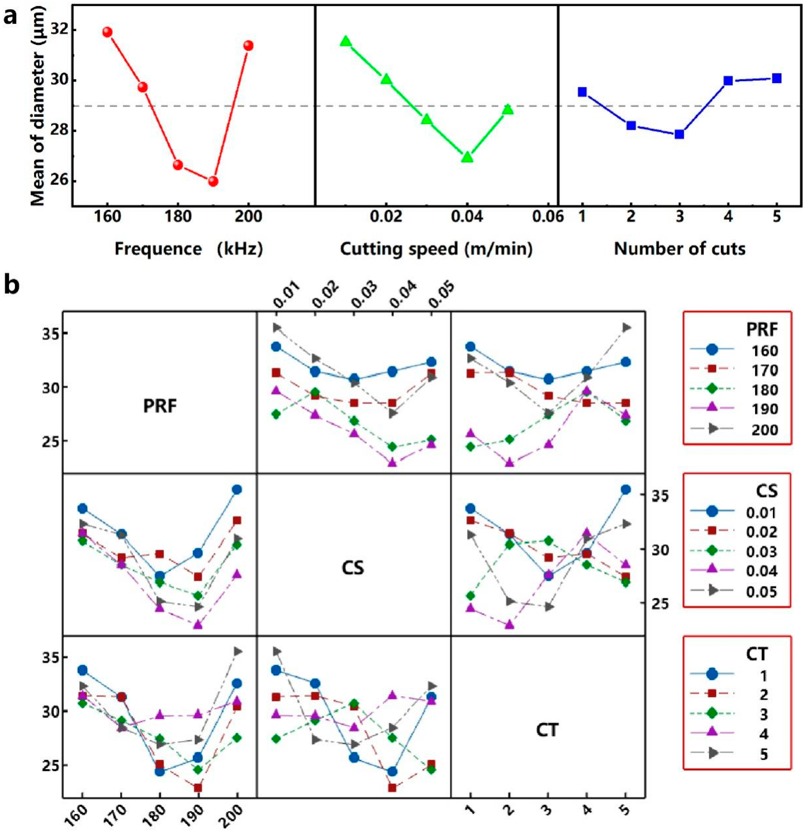
3.2. Variance Analysis of the L25(53) Orthogonal Experiments

Range is the difference between the maximum values and the minimum values of the experimental results. Range analysis can quickly determine the optimal level of a single factor and the optimal level combination of multiple factors in an orthogonal experiment. When the evaluation index is the roundness, the results of the range analysis of each parameter parameter are shown in Table 5 and Figure 4a. The parameter parameter PRF has a range R1 of 0.706 μm for the evaluation index R. As the value of the PRF increases, the roundness value decreases continuously, and the best R is obtained at lever 5 (200 kHz). The range R2 and R3 of the process parameters CS and RNC are 0.681 and 0.201 μm, respectively. As the values of CS and RNC increase, the value of R also decreases, and the roundness is optimal at a cutting speed level of 5 (50 mm/s) and a cutting number level of 5 (5). Therefore, in this orthogonal experiment, the optimal R can be obtained when the parameter parameter combination is 5-5-5. As shown in Table 4, the through-hole can be obtained when the parameter combination is 5 (200 kHz) - 5 (50 mm/s) - 4 (4). Therefore, for the optimum parameter parameter combination 5(200 kHz) - 5(50 mm/s) - 5 (5), the through-hole can also be obtained in the case of only increasing RNC compared with the parameter parameter combination 5-5-4. In the range analysis of the orthogonal experiment, the larger the value of the range R, the greater the influence of the process parameters on the evaluation index. Comparing the values of R1, R2 and R3, it is known that RNC, CS and PRF have an increased influence on the roundness of micro-hole in this orthogonal experiment.
The interactive diagram obtained through the interactive analysis can show how the relationship between a parameter parameter and an evaluation indicator depends on the value of the second parameter parameter. Figure 4b shows the interactions between each parameter parameter for roundness. The interaction analysis between the process parameters corresponding to the optimal roundness (200 kHz-50 mm/s-4) shows that (1) when the PRF level is 200 kHz, the interaction between CS and PRF is smaller than other PRF levels, and the interaction is smallest when the CS level is 50 mm/s. (2) When the PRF level is 200 kHz, the interaction between RNC and PRF is small compared to other PRF levels, but the interaction is greatest when the RNC level is 5. (3) When the CS level is 50 mm/s, the interaction between RNC and CS is smaller than the other CS level, and when the RNC level is 5, the interaction is larger than other RNC levels.
When the evaluation index is the diameter of the micro-hole, the results of the range analysis of each parameter parameter are shown in Table 6 and Figure 5a: (1) The parameter parameter PRF has a range R1 of 5.932 μm, and the optimum parameter parameter level is 4 (190 kHz); (2) the parameter parameter CS has a range R2 of 4.608 μm, and the optimum parameter parameter level is 4 (40 mm/s); (3) the parameter parameter RNC has a range R3 of 1.680 μm, and the optimum parameter parameter level is 3 (3). As shown in Table 4, the through-hole can be obtained when the parameter parameter combination is 5 (200 kHz) - 4 (40 mm/s) - 3 (3). Therefore, for the optimum parameter parameter combination 4 (190 kHz) - 4 (40 mm/s) - 3 (3), the through-hole can also be obtained in the case of only reducing the output power compared with the parameter parameter combination 5-4-3. Comparing the values of R1, R2 and R3, it is known that RNC, CS and PRF have an increased influence on the diameter of micro-hole in this orthogonal experiment. For the combination of process parameters (190 kHz - 40 mm/s - 3) corresponding to the optimal diameter of the micro-hole, it can be known from the interaction analysis in Figure 5b: (1) when the PRF level is 190 kHz, the interaction is smallest when the CS level is 40 mm/s. (2) When the PRF level is 190 kHz, the interaction is relatively small when RNC level is 3. (3) When the CS level is 40 mm/s, the interaction is middle when the RNC level is 3.
Similarly, when the evaluation index is the size of the HAZ, the results of the range analysis of each parameter parameter are shown in Table 7 and Figure 6a: (1) the parameter parameter PRF has a range R1 of 1.157 μm, and the optimum parameter parameter level is 4 (190 kHz); the parameter parameter CS has a range R2 of 0.637 μm, and the optimum process parameter level is 4 (40 mm/s); the parameter parameter RNC has a range R3 of 0.047 μm, and the optimum parameter parameter level is 3 (3). As shown in Table 4, the through-hole can be obtained when the parameter parameter combination is 5 (200 kHz) - 4 (40 mm/s) - 3 (3). Therefore, for the optimum parameter parameter combination 4 (190 kHz) - 4 (40 mm/s) - 3 (3), the through-hole can also be obtained in the case of only reducing the output power compared with the parameter parameter combination 5-4-3. Comparing the values of R1, R2 and R3, it is known that RNC, CS and PRF have an increased influence on the diameter of micro-hole in this orthogonal experiment. For the combination of process parameters (190 kHz - 40 mm/s - 3) corresponding to the optimal size of HAZ, it can be known from the interaction analysis in Figure 6b: (1) when the PRF level is 190 kHz, the interaction is smallest when the CS level is 40 mm/s. (2) When the PRF level is 190 kHz, the interaction is relatively small when RNC level is 3. (3) When the CS level is 40 mm/s, the interaction is relatively large when the RNC level is 3.
According to the range analysis results of the orthogonal experiment, the effect of each parameter parameter on the diameter of micro-hole and HAZ was approximate, and the minimum diameter and HAZ were obtained at the same parameter level combination of 4(190 kHz) - 4(40 mm/s) - 3(3). As shown in Table 5, the roundness corresponding to each parameter parameter at this parameter level was 0.810 μm (PRF), 0.791 μm (CS), 0.976 μm (RNC), respectively. In the combination of parameter level to obtain the best roundness, the roundness corresponding to each parameter parameter was 0.692 μm (PRF), 0.667 μm (CS), 0.869 μm (RNC). Although the parameter level combination (5-5-5) that achieves the best roundness was inconsistent with this parameter level combination (4-4-3), the roundness difference of each parameter parameter was more than 0.13 μm. Therefore, parameter level combination of 4(190 kHz) - 4(40 mm/s) - 3(3) was selected as the optimal parameter level combination of laser micro-cutting in this study. It should be emphasized that in this parameter parameter combination, the interaction of PRF-CS and PRF-RNC is small, and the interaction of CS-RNC is large.

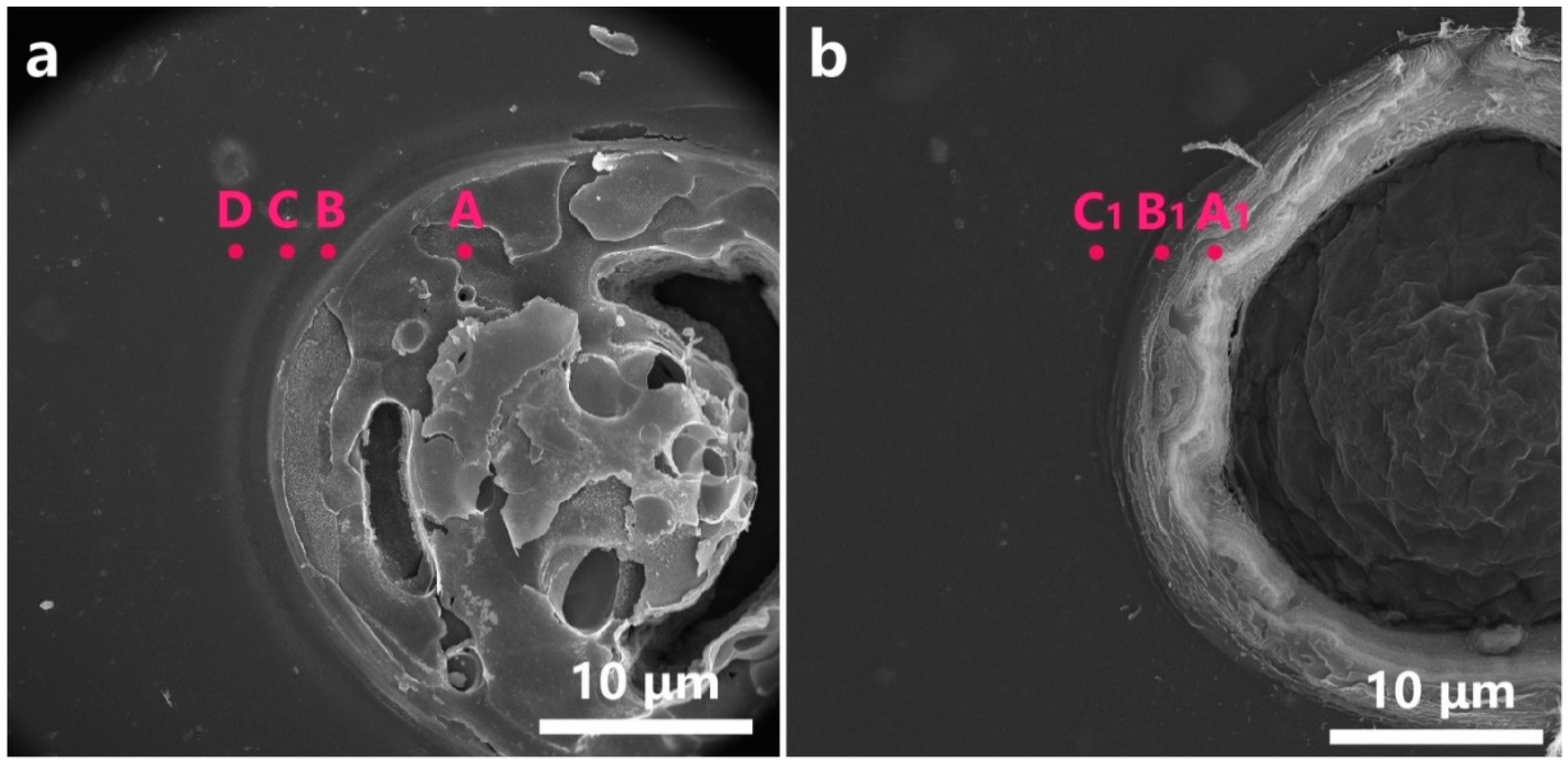
3.3. Mechanism of Laser Micro-Cutting

In order to determine how the process parameters affect the quality of the micro-holes, it is important to understand the interaction mechanism between the nanosecond UV laser and the ultra-thin PI film. Figure 7 shows the typical morphology of the micro-hole before and after cleaning. As shown in Figure 7a, after the laser micro-cutting, a circular area having a diameter of several tens of micrometers is formed through the PI film, the material in the micro-hole is not completely removed and a layered halo appears around this circular area. As shown in Figure 7b, the layered halo around the micro-hole disappeared after cleaning and the material in the micro-hole was removed, indicating that by-products of laser cutting could be removed.
Further, the product of the laser micro-cutting was analyzed by Raman spectra and energy dispersion spectrum (EDS). Before cleaning, as shown in Figure 7a, the A-D points were selected from the inside of the micro-hole to the periphery of the layered halo for Raman analysis. There are no other peaks except the D band and the G band of point A at 1356 and 1594 cm−1 (Figure 8a), which indicates that the main component in the micro-hole after laser micro-cutting is carbon [35,36]. For the Raman spectra from point B to point D, there are no obvious peaks nor carbon peaks, which indicates that there are no new chemical bonds generated in the layered halo, and the carbon is not sputtered out from the micro-hole. According to the EDS analysis of these points, as shown in Table 8, the carbon content (97.99%) is much higher than the other positions, which further confirms the above-mentioned laser carbonization process.
After cleaning, as shown in Figure 7b, the point A1 on the inner wall of the micro-hole, the point B1 on the HAZ, and the point C1 outside the HAZ were selected for Raman and EDS analysis. There are no obvious peaks or carbon peaks on the Raman curve in Figure 8b, indicating that the composition of each position is basically the same after cleaning. Points A1, B1, and C1 have little difference in elemental content (Table 8), further indicating that there is no significant difference in the material surrounding the micro-hole after cleaning.
As shown in Figure 9, to analyze the dynamic change course of PI during laser heating, thermogravimetric analysis was performed on this ultra-thin PI film. According to the TGA curve, the plateau period is within 460 °C, and then the reaction period begins. Moreover, the thermal degradation process of PI film, a thermosetting material, is mainly one-step degradation. Thus, the weight loss step can be attributed to the carbonization process of the sample. As shown in the DTA curve, the temperature difference between the sample and the reference during heating (ΔT) is always less than zero, indicating that the PI film continues to absorb heat during thermal decomposition. The DTA curve has a peak at 619 °C, when the heat absorption rate is the highest and the weight loss rate is also the highest. In combination with the analysis of Figure 7 and Figure 8 and Table 8, PI is carbonized at high temperature and remains on the inner wall, and the short-chain polyimide component is sputtered outside the micro-hole. In addition, because of thermal diffusion, wrinkles as shown in Figure 2 are produced around the micro-hole.
With heating-carbonization as the core, the influence of the laser micro-cutting process parameters on these evaluation indexes was discussed. The nanosecond UV laser carbonizes the PI film by high temperature on a circular cutting path to form a micro-hole, and the carbonized material remains in the micro-hole. Short-chain polyimide molecules that are partially decomposed but not yet charred will sputter on the outside of the micropores to form a halo. These products can be removed by cleaning, and a wrinkled HAZ formed by thermal diffusion can be clearly observed. Under the conditions of other process parameters unchanged: (1) the higher the PRF value, the lower the output power and the smaller the carbonization diameter of the spot; (2) the faster the CS, the less heat accumulation effect, and the smaller the carbonization diameter of the spot; (3) the more RNC, the more times the material is removed by the heat accumulation effect, and the larger the carbonization area. Experiment results of roundness analysis shows that lower output power and higher CS are beneficial to reduce the heat accumulation effect, which helps to improve the roundness of the micro-holes. In addition, more RNC is conducive to sufficient carbonized material in the same path, thus improving the roundness of the micro-hole too. Lower output power and faster cutting speeds help to form smaller carbonization diameter of the spot, resulting in smaller micro-hole diameters, but may also result in the inability to carbonize the material. The best process parameters should be achieved with a small carbonization diameter and fast cutting speeds, while orthogonal experiments help to quickly screen out the best combinations (4-4-3). At the same time, the smaller the diameter of the carbonized region, the smaller the area affected by thermal diffusion (HAZ), as shown in the experiment results of diameter and HAZ analysis of the micro-holes.

3.4. Fabrication of the Ultra-Thin PI Film Contact Spacer

As shown in Figure 10, an ultra-thin PI contact spacer with an average circle center distance of 50 μm was fabricated using the optimal parameter parameter combination (4-4-3). In the randomly selected 10 samples, the average and variance of the roundness, diameter, and HAZ are 0.6 ± 0.3, 24.3 ± 2.3, 1.8 ± 1.1 μm. The SEM morphology shows that the micro-holes are evenly distributed on the PI film, and there are no obvious defects, such as non-through holes and irregular shapes, etc.

4. Conclusions

The contact spacer is the core component that regulates the measurement range and sensitivity of tactile sensors. Using nanosecond UV laser commonly used in industry, the interaction mechanism between laser and ultra-thin PI film was first studied, and the influence of laser process parameters on micro-cutting quality was explored by an orthogonal experiment. Finally, the ultra-thin PI film contact spacer was successfully fabricated, which laid the foundation for the industrial production of the tactile sensor. Specific conclusions are as follows:
The high temperature generated by the spot carbonizes the PI film and partially stays in the micro-hole. The short-chain polyimide component is sputtered outside the micro-hole during the laser micro-cutting. Thermal diffusion during laser micro-cutting causes wrinkles around the micro-hole.
In the orthogonal experiment of this study, with the increase of PRF, CS and RNC values, the circularity of micro-hole was gradually optimized, and the optimum roundness was obtained at a parameter level of 5(200 kHz) - 5(50 mm/s) - 5 (5).
In the orthogonal experiment of this study, the effect of each parameter parameter on the diameter of micro-hole and HAZ was approximate. The minimum diameter (24.3 ± 2.3 μm) and HAZ (1.8 ± 1.1 μm) were obtained at the same parameter level of 4(190 kHz) - 4(40 mm/s) - 3(3).

Author Contributions

Data curation, T.Z.; funding acquisition, Y.H. and Y.R.; methodology, C.W.; writing—original draft, C.W.; writing—review and editing, C.W., Y.H. and Y.R. All authors have read and agreed to the published version of the manuscript.

Funding

This work was supported by the National Natural Science Foundation of China (51905191), the Major Project of Science and Technology Innovation Special for Hubei Province (2018AAA027), and Wuhan Science and Technology Planning Project (201903070311520).

Institutional Review Board Statement

Not applicable.

Informed Consent Statement

Not applicable.

Data Availability Statement

Not applicable.

Acknowledgments

The general characterization facilities are provided by the Flexible Electronics Manufacturing Laboratory in Experiment Center for Advanced Manufacturing and Technology in School of Mechanical Science and Engineering of HUST.

Conflicts of Interest

The authors declare no conflict of interest.

References

  1. Nawrocki, R.A.; Matsuhisa, N.; Yokota, T.; Someya, T. 300-nm Imperceptible, Ultraflexible, and Biocompatible e-Skin Fit with Tactile Sensors and Organic Transistors. Adv. Electron. Mater. 2016, 2, 1500452. [Google Scholar] [CrossRef]
  2. Chen, S.; Jiang, K.; Lou, Z.; Chen, D.; Shen, G. Recent Developments in Graphene-Based Tactile Sensors and E-Skins. Adv. Mater. Technol. 2018, 3, 1700248. [Google Scholar] [CrossRef]
  3. Wu, C.; Tang, X.; Gan, L.; Li, W.; Zhang, J.; Wang, H.; Qin, Z.; Zhang, T.; Zhou, T.; Huang, J. High-Adhesion Stretchable Electrode via Cross-Linking Intensified Electroless Deposition on Biomimetic Elastomeric Micropore Film. ACS Appl. Mater. Interfaces 2019, 11, 20535–20544. [Google Scholar] [CrossRef]
  4. Schneider, A.; Sturm, J.; Stachniss, C.; Reisert, M.; Burkhardt, H.; Burgard, W. Object Identification with Tactile Sensors using Bag-of-Features. In Proceedings of the 2009 IEEE/RSJ International Conference on Intelligent Robots and Systems, St. Louis, MO, USA, 10–15 October 2009. [Google Scholar]
  5. Jamone, L.; Natale, L.; Metta, G.; Sandini, G. Highly Sensitive Soft Tactile Sensors for an Anthropomorphic Robotic Hand. IEEE Sens. J. 2015, 15, 4226–4233. [Google Scholar] [CrossRef]
  6. Yuan, W.; Dong, S.; Adelson, E.H. GelSight: High-Resolution Robot Tactile Sensors for Estimating Geometry and Force. Sensors 2017, 17, 2762. [Google Scholar] [CrossRef] [Green Version]
  7. Ahn, Y.; Song, S.; Yun, K.-S. Woven flexible textile structure for wearable power-generating tactile sensor array. Smart Mater. Struct. 2015, 24, 075002. [Google Scholar] [CrossRef]
  8. Guo, X.; Huang, Y.; Cai, X.; Liu, C.; Liu, P. Capacitive wearable tactile sensor based on smart textile substrate with carbon black/silicone rubber composite dielectric. Meas. Sci. Technol. 2016, 27, 045105. [Google Scholar] [CrossRef]
  9. Yeo, J.C.; Liu, Z.; Zhang, Z.Q.; Zhang, P.; Wang, Z.; Lim, C.T. Wearable mechanotransduced tactile sensor for haptic perception. Adv. Mater. Technol. 2017, 2, 1700006. [Google Scholar] [CrossRef]
  10. Kwon, D.; Lee, T.-I.; Shim, J.; Ryu, S.; Kim, M.S.; Kim, S.; Kim, T.-S.; Park, I. Interfaces, highly sensitive, flexible, and wearable pressure sensor based on a giant piezocapacitive effect of three-dimensional microporous elastomeric dielectric layer. ACS Appl. Mater. Interfaces 2016, 8, 16922–16931. [Google Scholar] [CrossRef]
  11. Qiu, Z.; Wan, Y.; Zhou, W.; Yang, J.; Yang, J.; Huang, J.; Zhang, J.; Liu, Q.; Huang, S.; Bai, N.; et al. Ionic skin with biomimetic dielectric layer templated from calathea zebrine leaf. Adv. Funct. Mater. 2018, 28, 1802343. [Google Scholar] [CrossRef]
  12. Chen, Z.; Wang, Z.; Li, X.; Lin, Y.; Luo, N.; Long, M.; Zhao, N.; Xu, J.-B. Flexible piezoelectric-induced pressure sensors for static measurements based on nanowires/graphene heterostructures. ACS Nano 2017, 11, 4507–4513. [Google Scholar] [CrossRef]
  13. Wu, W.; Wen, X.; Wang, Z.L.J.S. Taxel-addressable matrix of vertical-nanowire piezotronic transistors for active and adaptive tactile imaging. Science 2013, 340, 952–957. [Google Scholar] [CrossRef] [Green Version]
  14. Fan, F.-R.; Lin, L.; Zhu, G.; Wu, W.; Zhang, R.; Wang, Z.L. Transparent triboelectric nanogenerators and self-powered pressure sensors based on micropatterned plastic films. Nano Lett. 2012, 12, 3109–3114. [Google Scholar] [CrossRef] [Green Version]
  15. Zhu, B.; Niu, Z.; Wang, H.; Leow, W.R.; Wang, H.; Li, Y.; Zheng, L.; Wei, J.; Huo, F.; Chen, X.J.S. Microstructured graphene arrays for highly sensitive flexible tactile sensors. Small 2014, 10, 3625–3631. [Google Scholar] [CrossRef]
  16. Pyo, S.; Lee, J.; Kim, W.; Jo, E.; Kim, J. Multi-Layered, Hierarchical Fabric-Based Tactile Sensors with High Sensitivity and Linearity in Ultrawide Pressure Range. Adv. Funct. Mater. 2019, 29, 1902484. [Google Scholar] [CrossRef]
  17. Liu, W.; Liu, N.; Yue, Y.; Rao, J.; Cheng, F.; Su, J.; Liu, Z.; Gao, Y.J.S. Piezoresistive pressure sensor based on synergistical innerconnect polyvinyl alcohol nanowires/wrinkled graphene film. Small 2018, 14, 1704149. [Google Scholar] [CrossRef]
  18. Tang, X.; Wu, C.; Gan, L.; Zhang, T.; Zhou, T.; Huang, J.; Wang, H.; Xie, C.; Zeng, D.J.S. Multilevel Microstructured Flexible Pressure Sensors with Ultrahigh Sensitivity and Ultrawide Pressure Range for Versatile Electronic Skins. Small 2019, 15, 1804559. [Google Scholar] [CrossRef] [PubMed]
  19. Doostani, N.; Darbari, S.; Mohajerzadeh, S.; Moravvej-Farshi, M.K. Fabrication of highly sensitive field emission based pressure sensor, using CNTs grown on micro-machined substrate. Sens. Actuators A Phys. 2013, 201, 310–315. [Google Scholar] [CrossRef]
  20. Luo, C.; Liu, N.; Zhang, H.; Liu, W.; Yue, Y.; Wang, S.; Rao, J.; Yang, C.; Su, J.; Jiang, X.J.N.E. A new approach for ultrahigh-performance piezoresistive sensor based on wrinkled PPy film with electrospun PVA nanowires as spacer. Nano Energy 2017, 41, 527–534. [Google Scholar] [CrossRef]
  21. Wu, C.Y.; Zhang, T.; Zhang, J.; Huang, J.; Tang, X.; Zhou, T.; Rong, Y.; Huang, Y.; Shi, S.; Zeng, D. A new approach for an ultrasensitive tactile sensor covering an ultrawide pressure range based on the hierarchical pressure-peak effect. Nanoscale Horiz. 2019, 4, 1277–1285. [Google Scholar] [CrossRef] [PubMed]
  22. Armon, N.; Greenberg, E.; Edri, E.; Kenigsberg, A.; Piperno, S.; Kapon, O.; Fleker, O.; Perelshtein, I.; Cohen-Taguri, G.; Hod, I.; et al. Simultaneous laser-induced synthesis and micro-patterning of a metal organic framework. Chem. Commun. (Camb. Engl.) 2019, 55, 12773–12776. [Google Scholar] [CrossRef]
  23. Hsiao, W.-T.; Tseng, S.-F.; Huang, K.-C.; Chiang, D. Electrode patterning and annealing processes of aluminum-doped zinc oxide thin films using a UV laser system. Opt. Lasers Eng. 2013, 51, 15–22. [Google Scholar] [CrossRef]
  24. Kim, H.; Auyeung, R.C.Y.; Lee, S.H.; Huston, A.L.; Pique, A. Laser-printed interdigitated Ag electrodes for organic thin film transistors. J. Phys. D Appl. Phys. 2010, 43, 085101. [Google Scholar] [CrossRef]
  25. Antonczak, A.J.; Stepak, B.D.; Szustakiewicz, K.; Wojcik, M.R.; Abramski, K.M. Degradation of poly(l-lactide) under CO_2 laser treatment above the ablation threshold. Polym. Degrad. Stab. 2014, 109, 97–105. [Google Scholar] [CrossRef]
  26. Stepak, B.; Antończak, A.J.; Szustakiewicz, K.; Pezowicz, C.; Abramski, K.M. The influence of ArF excimer laser micromachining on physicochemical properties of bioresorbable poly(L-lactide). In Proceedings of the SPIE LASE Laser-based Micro-& Nanoprocessing X, San Francisco, CA, USA, 13–18 February 2016. [Google Scholar]
  27. Stepak, B.D.; Antonczak, A.J.; Szustakiewicz, K.; Koziol, P.E.; Abramski, K.M. Degradation of poly(L-lactide) under KrF excimer laser treatment. Polym. Degrad. Stab. 2014, 110, 156–164. [Google Scholar] [CrossRef]
  28. Jayakumar, M.K.G.; Idris, N.M.; Zhang, Y. Remote activation of biomolecules in deep tissues using near-infrared-to-UV upconversion nanotransducers. Proc. Natl. Acad. Sci. USA 2012, 109, 8483–8488. [Google Scholar] [CrossRef] [Green Version]
  29. Rong, Y.; Huang, Y.; Li, M.; Zhang, G.; Wu, C. High-quality cutting polarizing film (POL) by 355 nm nanosecond laser ablation. Opt. Laser Technol. 2021, 135, 106690. [Google Scholar] [CrossRef]
  30. Wu, C.; Li, M.; Huang, Y.; Rong, Y. Cutting of polyethylene terephthalate (PET) film by 355 nm nanosecond laser. Opt. Laser Technol. 2021, 133, 106565. [Google Scholar] [CrossRef]
  31. Wu, C.; Rong, Y.; Huang, Y.; Li, M.; Zhang, G.; Liu, W. Precision cutting of polyvinyl chloride film by ultraviolet nanosecond laser. Mater. Manuf. Process. 2021. [Google Scholar] [CrossRef]
  32. Lassithiotaki, M.; Athanassiou, A.; Anglos, D.; Georgiou, S.; Fotakis, C. Photochemical effects in the UV laser ablation of polymers: Implications for laser restoration of painted artworks. Appl. Phys. A Mater. Sci. Process. 1999, 69, 363–367. [Google Scholar] [CrossRef]
  33. Schmidt, H.; Ihlemann, J.; Wolff-Rottke, B.; Luther, K.; Troe, J. Ultraviolet laser ablation of polymers: Spot size, pulse duration, and plume attenuation effects explained. J. Appl. Phys. 1998, 83, 5458–5468. [Google Scholar] [CrossRef]
  34. Yingling, Y.G.; Garrison, B.J. Photochemical induced effects in material ejection in laser ablation. Chem. Phys. Lett. 2002, 364, 237–243. [Google Scholar] [CrossRef]
  35. Tang, J.; Yamauchi, Y. Carbon materials: MOF morphologies in control. Nat. Chem. 2016, 8, 638–639. [Google Scholar] [CrossRef]
  36. Zhang, L.; Ding, L.X.; Chen, G.F.; Yang, X.; Wang, H. Ammonia Synthesis under Ambient Conditions: Selective Electroreduction of Dinitrogen to Ammonia on Black Phosphorus Nanosheets. Angew. Chem. Int. Ed. 2019, 131, 2638–2642. [Google Scholar] [CrossRef]
Figure 1. Experimental setup of PI film cutting process.
Micromachines 12 00908 g001
Figure 2. Schematic diagram of laser cutting quality evaluation.
Micromachines 12 00908 g002
Figure 3. Typical confocal microscope image of each sample.
Micromachines 12 00908 g003
Figure 4. (a) Effect of process parameters on roundness. (b) Interactions between each parameter parameter for roundness.
Micromachines 12 00908 g004
Figure 5. (a) Effect of process parameters on diameter of the micro-hole. (b) Interactions between each parameter parameter for diameter of the micro-hole.
Micromachines 12 00908 g005
Figure 6. (a) Effect of process parameters on size of HAZ. (b) Interactions between each parameter parameter for size of HAZ.
Micromachines 12 00908 g006
Figure 7. SEM images of the micro-hole (a) before cleaning and (b) after cleaning.
Micromachines 12 00908 g007
Figure 8. Raman measurements in different points in (a) Figure 7a and (b) Figure 7b.
Micromachines 12 00908 g008
Figure 9. TGA and DTA curves of the ultra-thin PI film.
Micromachines 12 00908 g009
Figure 10. (a) Low- and (b) high-magnification SEM images of the ultra-thin PI film contact spacer.
Micromachines 12 00908 g010
Table 1. Correspondent relationship between input PRF and output power.
Frequency (kHz)100120140160180200
Laser output power (W)16.114.112.310.39.59.0
Actual cutting power (W)0.1590.1370.1210.1020.940.89
Table 2. Micro-cutting process parameters and levels.
Process ParametersUnitNotationFactor Levels
12345
Pulse repetition frequencykHzPRF160170180190200
Cutting speedmm/sCS1020304050
Repetition number of cuts——CT12345
Table 3. L25(53) orthogonal experiments.
NO.ABCPRFCSRNC
11111600.011
21221600.022
31331600.033
41441600.044
51551600.055
62121700.012
72231700.023
82341700.034
92451700.045
102511700.051
113131800.013
123241800.024
133351800.035
143411800.041
153521800.052
164141900.014
174251900.025
184311900.031
194421900.042
204531900.053
215152000.015
225212000.021
235322000.032
245432000.043
255542000.054
Table 4. Experimental results L25(53) orthogonal experiments.
NO.PRF
(kHz)
CS
(mm/s)
RNCRoundness
(μm)
Diameter
(μm)
Width of HAZ
(μm)
TH
11601012.14333.7943.972No
21602021.82231.4103.646No
31603031.34230.7073.426Yes
41604040.98031.4193.295Yes
51605050.70532.3043.503Yes
61701021.48031.3143.562No
71702031.21729.1443.187Yes
81703041.08528.4743.093Yes
91704050.90728.4812.725Yes
101705010.87531.2793.136No
111801031.06227.3933.059Yes
121802040.91529.5603.018Yes
131803050.82526.8462.959Yes
141804010.79324.3642.688No
151805020.66825.0513.074No
161901041.06829.6132.806Yes
171902050.92327.3422.662Yes
181903010.77825.6492.551No
191904020.67022.8061.848No
201905030.61224.5652.191No
212001050.98535.4923.272Yes
222002010.76032.6182.681No
232003020.64030.4332.797Yes
242004030.60327.4942.930Yes
252005040.47330.8832.772Yes
Table 5. Range analysis table based on roundness evaluation.
PRF (kHz)CS (mm/s)RNC
K 1 ¯ 1.3981.3481.070
K 2 ¯ 1.1131.1271.056
K 3 ¯ 0.8530.9340.967
K 4 ¯ 0.8100.7910.904
K 5 ¯ 0.6920.6670.869
Optimal level555
Rj0.7060.6810.201
Order of rangeR1 > R2 > R3
Table 6. Range analysis table based on diameter of the micro-hole.
PRF (kHz)CS (mm/s)RNC
K 1 ¯ 31.92731.52129.541
K 2 ¯ 29.73830.01528.203
K 3 ¯ 26.64328.42227.861
K 4 ¯ 25.99526.91329.990
K 5 ¯ 31.38428.81730.093
Optimal level443
Rj5.9324.6081.680
Order of rangeR1 > R2 > R3
Table 7. Range analysis table based on size of the HAZ.
PRF (kHz)CS (mm/s)RNC
K 1 ¯ 3.5683.3343.005
K 2 ¯ 3.1403.0392.985
K 3 ¯ 2.9602.9652.959
K 4 ¯ 2.4122.6972.996
K 5 ¯ 2.8902.9353.024
Optimal level443
Rj1.1570.6370.047
Order of rangeR1 > R2 > R3
Table 8. The atomic percentage in the designated area in Figure 7 before and after cleaning.
Atomic PercentageCON
Point A97.990.861.15
Point B73.3719.517.12
Point C81.8812.935.19
Point D71.6420.947.42
Point A173.4419.387.18
Point B170.8720.698.44
Point C172.5819.567.86
Publisher’s Note: MDPI stays neutral with regard to jurisdictional claims in published maps and institutional affiliations.

