Article

Compact TSA with Anti-Spiral Shape and Lumped Resistors for UWB Applications

1
College of Electronic and Electrical Engineering, Henan Normal University, Xinxiang 453600, China
2
Henan Key Laboratory of Optoelectronic Sensing Integrated Application, Henan Normal University, Xinxiang 453600, China
3
Academician Workstation of Electromagnetic Wave Engineering of Henan Province, Henan Normal University, Xinxiang 453600, China
*
Authors to whom correspondence should be addressed.
Micromachines 2021, 12(9), 1029; https://doi.org/10.3390/mi12091029
Submission received: 16 July 2021 / Revised: 18 August 2021 / Accepted: 26 August 2021 / Published: 27 August 2021
(This article belongs to the Section E:Engineering and Technology)

Abstract

:
A novel compact tapered-slot-fed antenna (TSA) with anti-spiral shape and lumped resistors is presented for ultra-wideband (UWB) applications. Unique coplanar waveguide (CPW) to coplanar strip (CPS) feeding structure and exponential slot are designed to ensure the continuous current propagation and good impedance matching. With a pair of anti-spiral-shaped structure loadings at the end of the antenna, the radiation performance in lower operating band can be enhanced obviously. The typical resistor loading technique is applied to improve the time domain characteristics and expand the bandwidth. The fabricated prototype of this proposed antenna with a size of 53 × 63.5 mm2 was measured to confirm simulated results. The proposed antenna has S11 less than −10 dB in the range of 1.2–9.8 GHz, and the group delay result is only 0.4 ns. These findings indicate the proposed antenna can be taken as a promising candidate in UWB communication field.

1. Introduction

Ultra-wideband (UWB) technology can be taken as a powerful complement to narrowband technology due to its special characteristics, such as wide bandwidth, low profile, simple manufacturing, moderate gain in compact size, and endfire radiation pattern [1]. It is not only utilized in wireless communication, radar imaging and sounding, but also for human care monitoring and astronomy [2,3,4,5]. For the high integration requirement in the communication field, the volume of a mobile device is changed to lighter and tinier, and a miniature UWB antenna has become an indispensably technique during the communication design. Stripline-fed antenna constructed in the ground plane was the first realization of the tapered slot antenna (TSA). In addition, the first printed slot antenna and a double exponentially tapered slot antenna (DETSA) have been introduced and some conformal studies are also implemented for more promising applications [6,7]. In recent years, lots of different types of tapered slot antennas (TSAs) have been proposed and compared according to its specific application and technology requirement [8,9,10]. For wireless communication, it is important to know how to obtain large bandwidth and high gain through wide impedance matching structure and novel antenna shape in a compact size [11,12]. However, in time domain application, ensuring good signal fidelity is much more important, and some non-reflection optimization and loss loading are deployed to remove the reflected power from the discontinuous points and end truncation [13].
The TSA on a dielectric substrate attracts much attention for its small size, low cost and weight, easy manufacture, and wideband properties. The TSA mainly consists of two different parts, such as tapered radiation slot in coplanar or antipodal geometry and wideband feeding network for unbalance to balance transition between the RF front and the radiated section [14,15]. To achieve good performance for the antenna design, each part should be optimized carefully. In past decades, research on TSA has been published under different backgrounds and applications [16,17,18,19]. Coplanar TSA usually possesses wide bandwidth over two octaves with lower cross-polarization. However, feeding transition from the unbalanced port to the balanced slot faces great challenges [20]. At this moment, microstrip-to-slotline transition is highly used [21]. In contrast to one coplanar TSA, antipodal design can achieve much wider bandwidth due to natural UWB feeding transition, where the vertical E-field in microstrip line can be guided into inclined E-field from the top edge to bottom side of antipodal slot. Generally, the bandwidth of TSA is partly proportional to their length and aperture. In order to overcome this limitation, some modifications about the tapered slot and end truncation tips were implemented. For example, exponential or elliptical tapered slot were analyzed for better continuity and appropriate aperture, and the coplanar waveguide (CPW) to slot transitions were applied for better natural transformation [22,23]. Among these proposed UWB TSAs, the optimal antenna design should be one tradeoff choice according to the required small structure, easy manufacturing and convenient to be integrated with miniature RF front ends.
In this paper, we propose a modified coplanar TSA, which is terminated with two novel anti-spiral shape to enlarge the electrical aperture and reduce the reflection power. As the antenna aperture increases, the width of anti-spiral arms quickly sharpen as two curved horn of the buffalo. To further eliminate the reflections from the end tip, two lumped resistors are inserted at the half of the road path to largely absorb the residual current. Finally, one antenna prototype is fabricated and measured fully, and some analyses are implemented for better understanding the proposed antenna.

2. Slot Antenna Configuration and Design Consideration

2.1. Antenna Configuration

In the beginning, an antenna based on the CPW to coplanar strip (CPS) feed is proposed after reviewing some references, and better UWB characteristics and compact dimensions can be achieved by using the exponential equation with spiral curve at the termination of the antenna, in this process, the antenna has the disadvantage of tail current discontinuity and excessive current reflection at low frequencies. Thus, to obtain good fidelity of radiation signal and expand the low frequency characteristics of the antenna bandwidth, a resistor loading operation is performed at the end of the antenna. Thus, the final structure of the antenna is obtained. Figure 1a,b demonstrates the geometry of the proposed antenna, and the actual antenna prototype is shown in Figure 1c. It is notable that Figure 1a,b is just an illustrative image with the symbolic mark and position. The original antenna is constructed on an FR4 substrate. To obtain wider bandwidth and good signal fidelity, two lumped resistors in PCB footprint of 1210 are chosen. Meanwhile, to ensure the path continuity and smoothness, some radial fillet operation is made at the corner. The optimal dimensions of modified coplanar TSA are listed in Table 1.
The proposed antenna includes three independent parts, the CPW to CPS transition, the exponentially tapered slot, and the loaded anti-spiral shape. One polyline strip is introduced to transfer the unbalanced field in CPW into the balanced field in CPS. Below the dashed line C1 to C2, one exponential slot is designed to ensure the continuous current propagation and good impedance matching. The according exponential equation can be represented as Equation (1). The final anti-spiral loaded with the exponential part for frequency-independent characteristics at low frequency band can be described by Equation (2). In addition, to make good signal fidelity, two lumped resistors are inserted at the half path of the spiral.
y ( x ) = a e k k x + b 0   mm x 40 mm
{ x ( θ ) = r r 1 e k 0 θ cos ( θ ) y ( θ ) = r r 1 e k 0 θ sin ( θ ) 0 θ 3 π
where kk demonstrates the degree of the exponential curves. a and b are related to the length and width of the arms. r r 1 is the length of starting inner radius of the spiral curve and θ is the rotation angle of the spiral curve.

2.2. Parameter Study

To investigate the influence of the critical parameters on the electrical characteristics of the proposed antenna, a parametric study has been carried out. The simulated current distribution for the designed antenna on the center frequency point of 5.5 GHz is depicted in Figure 2. As the power propagation and radiation along the main slot, the residual current become small and low at the end, which illustrates the good impedance bandwidth and fidelity.
To evaluate the effect of fillet radius arc_rr, the size is increased from 3 to 6 mm with an interval of 1 mm. The response is shown in Figure 3. It can be observed that the arc_rr had little effect on the return loss. In fact, the main function for the fillet operation is to smooth the current path and eliminate some strong reflection points. Therefore, all of these curves have nearly identical shape and value among the whole frequency band.
Figure 4 shows the effect of exponential index kk on return loss. It is observed that the exponential index kk can affect the return loss, which is because that different tapered slot can induce the energy transition quality from feeding structure to radiated aperture unequal. As the value of kk increases, the return loss at 3.5 GHz also gradually increases, while the return loss at 6.5 GHz exhibits a decreasing trend. The same effect of initial radius r r 1 in spiral can be seen in Figure 5. For spiral curve, small r r 1 can quickly produce large difference at the exponential speed. Though the value only changes from 3.4 to 3.7 mm with a small step of 0.1 mm, the return loss between them exhibits different appearances. Moreover, r r 1 is the design parameter of the spiral radiator in the termination of antenna, the main difference brought by the change of this parameter is located at the joint position C1 to C2. Thus, for good bandwidth, to ensure the continuous current propagation path is important in design process.
For resistive loading, the primary role is to absorb the residual current at the low frequency band, so some evident changes should be seen at lower band. In Figure 6, we can find that the loaded resistor has little effect on the higher band, and nearly identical curves are kept. However, significant difference can be observed at lower band. Meanwhile, under different values, the lower cutoff frequency point is same but the variation tendency is widely different. When the loaded resistor value is 100 Ω , the return loss has better resonance status.
As is known, the resistive loading in the antenna can influence the radiation characteristics (see Figure 7). The simulated antenna efficiency before loading the resistor is about 70% to 90%, but there is a trap frequency around 1.5 GHz. By adding the resistive loading in the antenna, the radiation efficiency at low frequencies has been improved obviously, and at high frequencies can be enhanced except the range of 1.65–3.85 GHz. In addition, the maximum difference of insertion loss between them can be up to 1 dBi at 3 GHz.

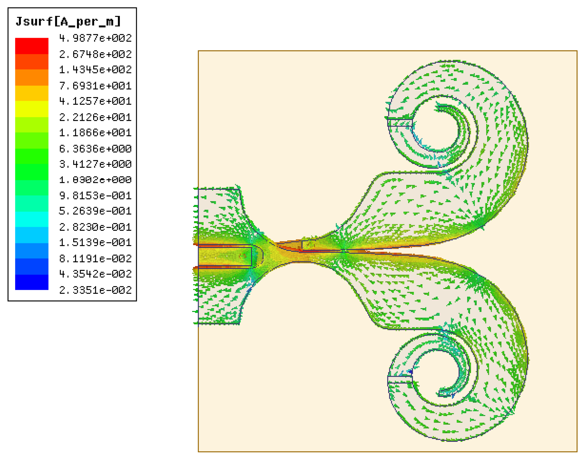
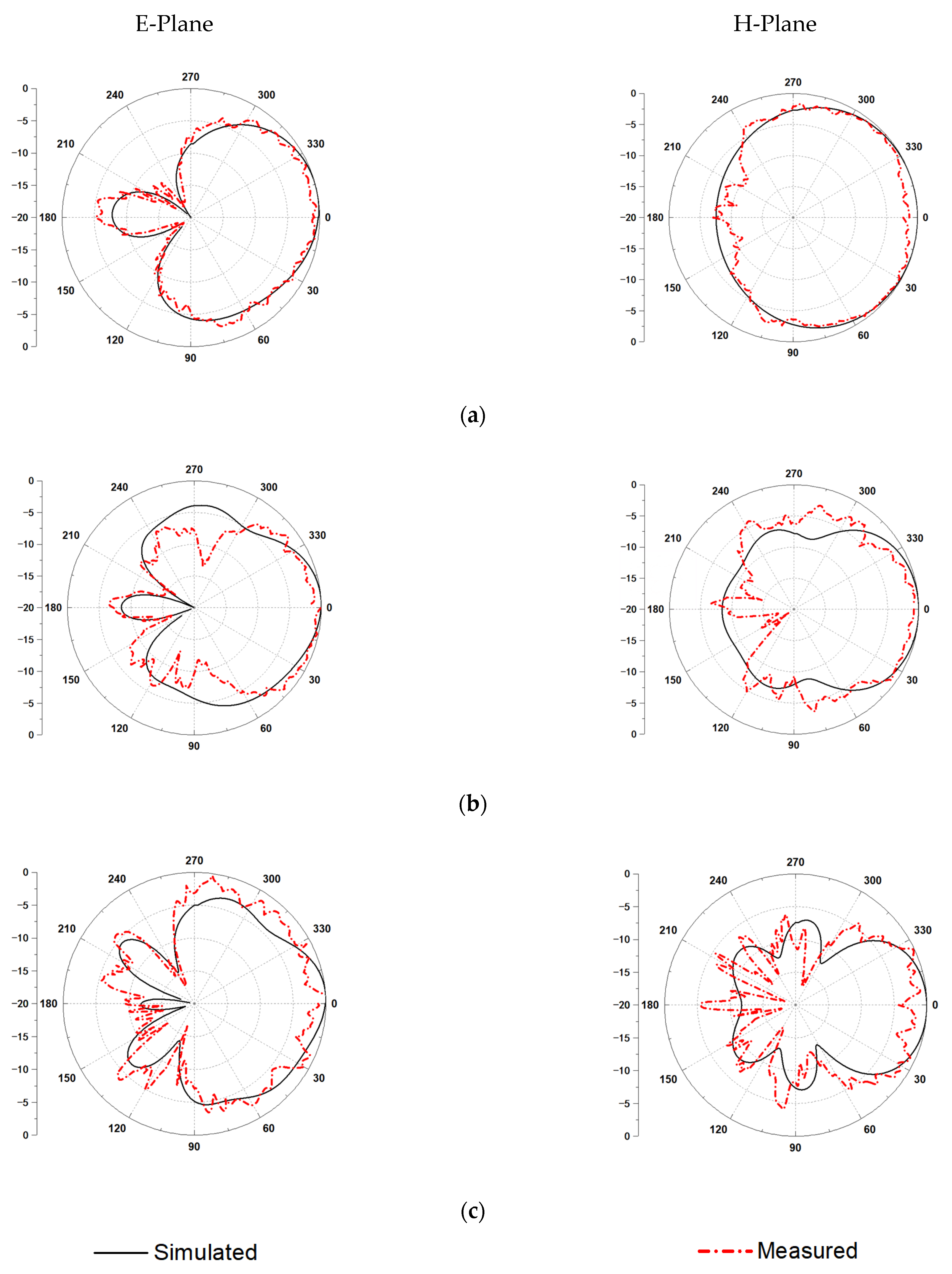
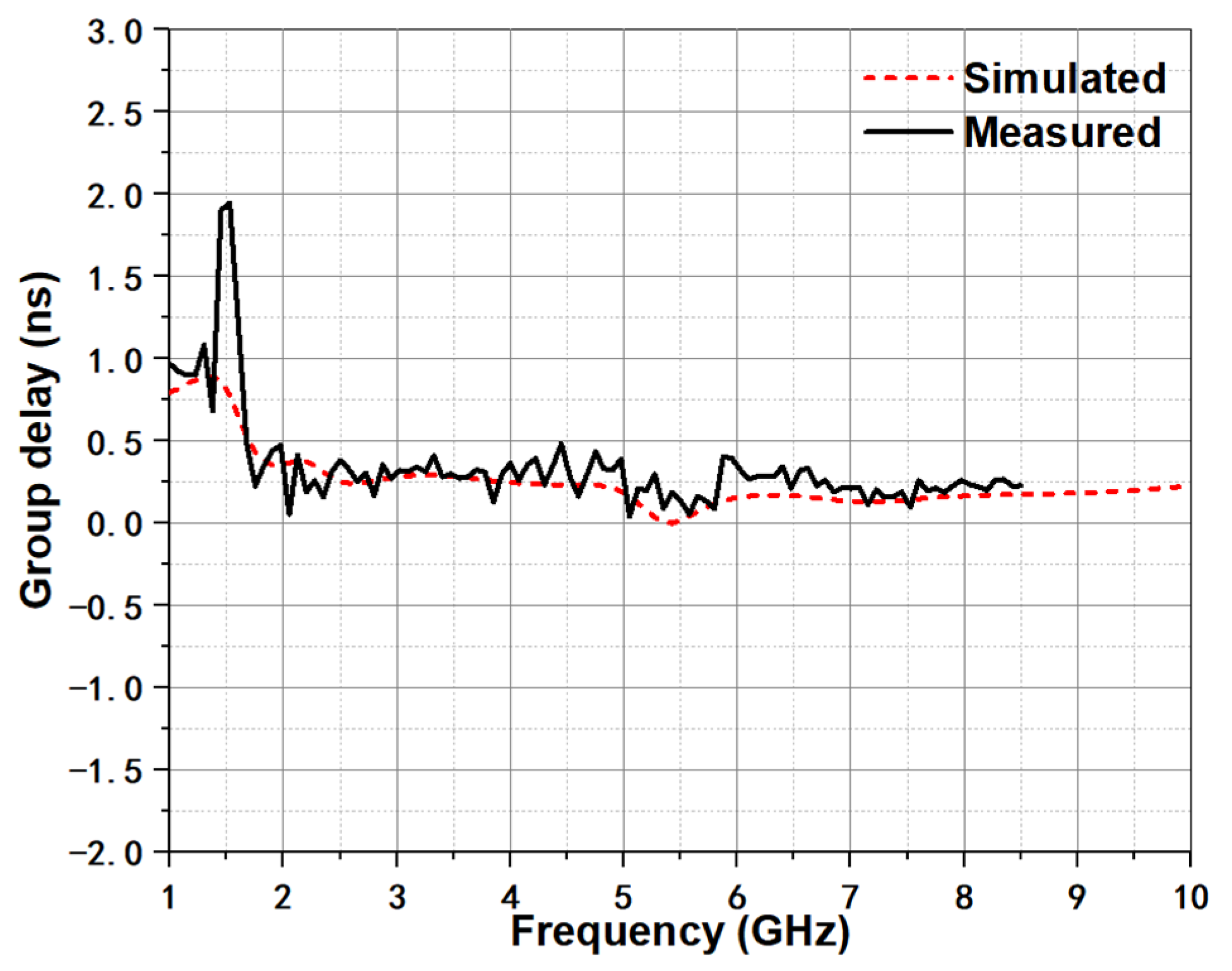
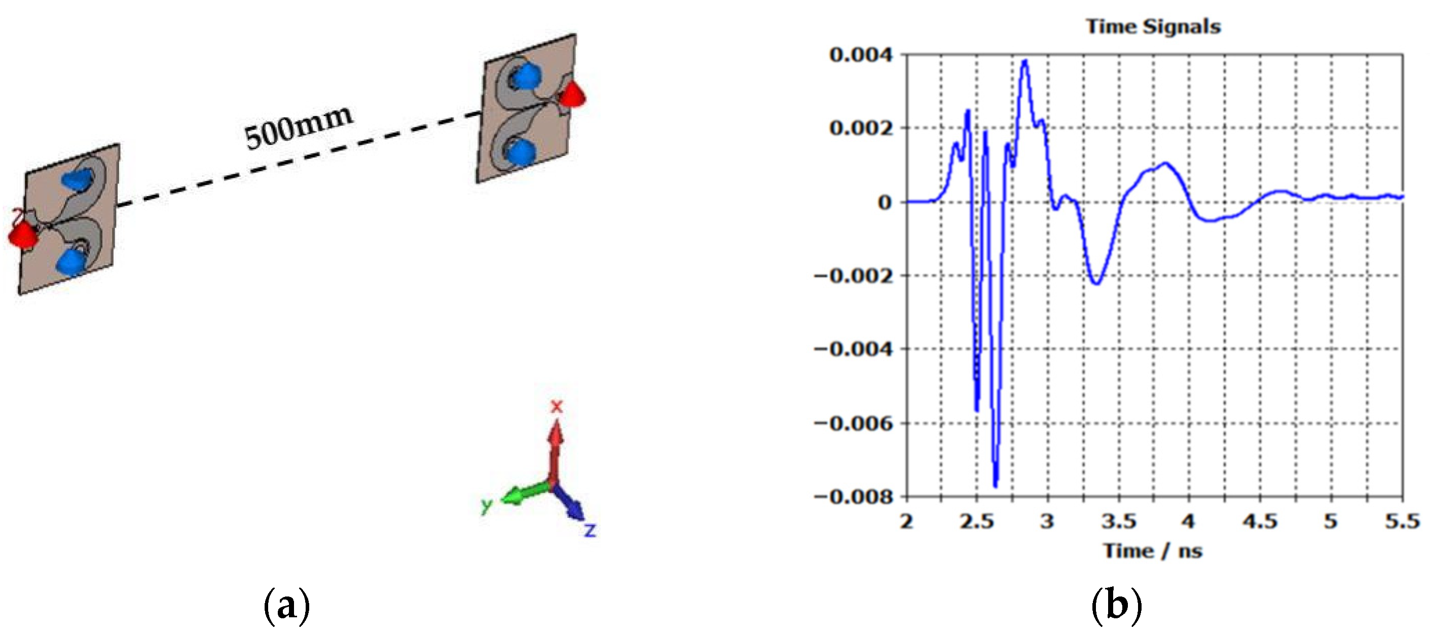
3. Results and Discussion

The compact UWB TSA is projected and optimized by two different 3-D full-wave electromagnetic simulation tools of Ansoft HFSS and CST, and the relevant parameters, such as return loss, radiation patterns, and group delay are measured by the Agilent vector network analyzer (VNA) E5071C (Keysight Technologies, Inc., Santa Rosa, DE, United States). Figure 8 displays the measured and simulated return loss of the proposed antenna, and the measurement is implemented just up to 8.5 GHz subject to VNA E5071C. The simulated impedance bandwidth with return loss better than −10 dB is 1.2–9.8 GHz. Moreover, the simulation and measurement agree well with each other. The small discrepancy between them is induced by the introduction of SMA connector and construction tolerance.
In addition, the normalized simulated and measured radiation patterns of 3, 5, and 7 GHz are exhibited in Figure 9. The radiation of the E-plane and H-plane shows good endfire characteristics in the working frequency band, and the simulation is well consistent with the measured results.
For good signal fidelity, group delay is one important index in time domain. Analyzed from the linear system perspective of the signal system, the delay fluctuation at each frequency point of group delay is equivalent to the phase change of the signal in this system, while the average constant of group delay is equal to time delay of the signal, which means the response to the signal is ahead or lagging. Thus, two antennas face-to-face 500 mm apart are built and then obtained the simulation results of group delay characteristics. In the actual measurement, the VNA E5071C with time domain analysis function was used for the tests. Figure 10 demonstrates the full comparison between measured and simulated group delay. It can be seen that the group delay of proposed antenna is around 0.4 ns. There exist agreement in measurement and simulation. In the working band, only 0.4 ns fluctuation can be seen, which largely ensured the in-band linear smoothness.
For many UWB applications, the antenna performance in time domain is very critical, which can largely influence the radiated signal quality in transceiver. To understand the ability for the proposed antenna, a pair of antennas is constructed face-to-face with the distance of 500 mm at identical height by CST, see Figure 11a, and one narrow Gaussian pulse is set as excited source with operating bandwidth from DC to 10 GHz. The final received signal is shown in Figure 11b. Large bandwidth and good input characteristics ensure very small ringing tails at the end of main wave.
Furthermore, Table 2 lists the comparison of presented antenna with other existing studies. Though the antenna proposed in [24,25,26,27] is comparatively smaller than that of this work, it is observed that the fractional bandwidth of the proposed antenna is relatively larger than the fractional bandwidth reported by the authors and the gain is comparable. The size and fractional bandwidth of the proposed antenna in this work is superior to that of the reported work in [28,29,30], as shown in Table 2. Although, the proposed antenna in [31,32,33,34] possess better gain and fractional bandwidth; nonetheless, with larger size, more expensive substrate, and worse group delay property. It can be observed that the proposed antenna has the advantages in compact size, fractional ultra-wide bandwidth, low cost, and good enough merit of gain. Therefore, it can be well suited for high-speed UWB applications.

4. Conclusions

A Compact TSA with a dimension of 53 × 63.5 mm2 for UWB applications is proposed and implemented in this paper. In the designed antenna, a unique CPW-CPS feeding structure and exponential slot are utilized. In addition, the final anti-spiral shape is loaded with the exponential part for frequency-independent characteristics and two lumped resistors are inserted at the half path of the spiral. A measured operating band from 1.2 to 9.8 GHz for S11 < −10 dB is obtained. The group delay result is only 0.4 ns and its up and down fluctuation is not more than 0.4 ns. The measurement is proved to be in accordance with simulation, which makes this antenna suitable for UWB communication systems.

Author Contributions

Conceptualization, X.-P.L. and G.X.; methodology, X.-P.L. and C.-J.D.; software, X.-P.L. and M.-R.M.; validation, G.X., M.-R.M. and W.L.; formal analysis, G.X. and C.-J.D.; investigation, X.-P.L., G.X. and W.L.; data curation, S.-E.S. and W.L.; writing-original draft preparation, G.X.; writing-review and editing, X.-P.L. and W.L.; supervision, X.-P.L.; funding acquisition, S.-E.S., W.L. and G.X. All authors have read and agreed to the published version of the manuscript.

Funding

This research was funded by the Key Scientific Research Projects of Colleges and Universities in Henan Province (19B510006), the Doctoral Scientific Research Start-up Foundation of Henan Normal University (5101239170009), and Postgraduate Research Innovation Project of Henan Normal University (YL202031).

Conflicts of Interest

The authors declare no conflict of interest.

References

  1. Federal Communications Commission (FCC). Revision of Part 15 of the Commision’s Rules Regarding Ultra-Wideband Transmission System; FCC Technical Report, ET-Docket 98-153; FCC: Washington, DC, USA, 2002. [Google Scholar]
  2. Bahadori, K.; Rahmat-Samii, Y. A Miniaturized elliptic-card UWB antenna with WLAN band rejection for Wireless communications. IEEE Trans. Antennas Propag. 2007, 55, 3326–3332. [Google Scholar] [CrossRef]
  3. Zhu, F.; Gao, S.; Ho, A.; Chan, H.; Alhameed, R.A.; Li, J.; Xu, J. Compact-size linearly tapered slot antenna for portable ultra-wideband imaging systems. Int. J. RF Microw. Comput.-Aided Eng. 2013, 23, 290–299. [Google Scholar] [CrossRef] [Green Version]
  4. Raza, A.; Lin, W.; Chen, Y.; Zhang, Y.; Chattha, H.; Sharif, A. Wideband tapered slot antenna for applications in ground penetrating radar. Microw. Opt. Technol. Lett. 2020, 62, 2562–2568. [Google Scholar] [CrossRef]
  5. Arts, M.; Maaskant, R.; Acedo, E.; Vaate, J. Broadband differentially fed tapered slot antenna array for radio astronomy applications. In Proceedings of the 2009 3rd European Conference on Antennas and Propagation(EuCAP), Berlin, Germany, 23–27 March 2009; pp. 2164–3342. [Google Scholar]
  6. Schaubert, D.H.; Aas, J.A.; Cooley, M.E.; Buris, N.E. Moment method analysis of infinite stripline-fed tapered slot antenna arrays with a ground plane. IEEE Trans. Antennas Propag. 1994, 2, 1161–1166. [Google Scholar] [CrossRef]
  7. Nikolaou, S.; Ponchak, G.E.; Papapolymerou, J.; Tentzeris, M.M. Double exponentially tapered slot antenna (DETSA) on liquid crystal polymer (LCP) for UWB applications. In Proceedings of the 2005 IEEE Antennas and Propagation Society International Symposium, Washington, DC, USA, 3–8 July 2005. [Google Scholar]
  8. Zhu, F.; Gao, S.; Ho, A.T.S.; Raed, A.A.; See, C.H.; Li, J.; Xu, J. Miniaturized tapered slot antenna with signal rejection in 5-6GHz band using a balun. IEEE Antennas Wirel. Propag. Lett. 2012, 11, 507–510. [Google Scholar]
  9. Abbosh, A.M. Miniaturized microstrip-fed tapered-slot antenna with ultrawideband performance. IEEE Antennas Wirel. Propag. Lett. 2009, 8, 690–692. [Google Scholar] [CrossRef] [Green Version]
  10. Tiwari, N.; Rao, T.R. Substrate integrated waveguide based antipodal linear tapered slot antenna for 60 GHz wireless communications. Appl. Comput. Electron. 2018, 33, 339–342. [Google Scholar]
  11. Yang, B.; Yu, Z.; Dong, Y.; Zhou, J.; Hong, W. Compact tapered slot antenna array for 5G millimeter-wave massive MIMO systems. IEEE Trans. Antennas Propag. 2017, 65, 6721–6727. [Google Scholar] [CrossRef]
  12. Min, Y.Z.; Sheng, X.Y.; Dong, W.W. A compact tapered slot antenna for ultrawideband applications. Microw. Opt. Technol. Lett. 2012, 55, 295–299. [Google Scholar]
  13. Shao, J.; Fang, G.; Ji, Y.; Tan, K.; Yin, H. A novel compact tapered-slot antenna for GPR applications. IEEE Antennas Wirel. Propag. Lett. 2013, 12, 972–975. [Google Scholar] [CrossRef]
  14. De Lera Acedo, E.; Garcia, E.; GonzÁlez-Posadas, V.; Vazquez-Roy, J.L.; Maaskant, R.; Segovia, D. Study and design of a differentially-fed tapered slot antenna array. IEEE Trans. Antennas Propag. 2009, 58, 68–78. [Google Scholar] [CrossRef] [Green Version]
  15. Liu, P.; Zhu, X.; Jiang, Z.H.; Zhang, Y.; Tang, H.; Hong, W. A compact single-layer Q-band tapered slot antenna array with phase-shifting inductive windows for endfire patterns. IEEE Trans. Antennas Propag. 2019, 67, 169–178. [Google Scholar] [CrossRef]
  16. Pandey, G.K.; Meshram, M.K. A printed high gain UWB vivaldi antenna design using tapered corrugation and grating elements. Int. J. RF Microw. Comput.-Aided Eng. 2015, 25, 610–618. [Google Scholar] [CrossRef]
  17. Hirano, T.; Hirose, A. Wideband and low direct-coupling tapered slot antenna using electromagnetic bandgap structures. IEEE Trans. Antennas Propag. 2019, 67, 2272–2279. [Google Scholar] [CrossRef]
  18. Yang, Z.; Guo, L.; Yao, C.; Zhang, Q.; Wang, Z. Ultra-wideband antipodal tapered slot antenna with gradient refractive index metamaterial lens. IEEE Antennas Wirel. Propag. Lett. 2019, 18, 2741–2745. [Google Scholar] [CrossRef]
  19. Kim, S.; Yu, H.; Choi, K.; Choi, D. Analysis of tapered slot antenna with high gain for 2D indoor wireless positioning. IEEE Access 2019, 7, 54312–54320. [Google Scholar] [CrossRef]
  20. Alsulaiman, S.; Ashraf, M.A.; Jamil, K.; Shoaib, M.; Alshebieli, S. Compact size tapered slot antenna array for ultra broadband applications. Microw. Opt. Technol. Lett. 2017, 59, 26–31. [Google Scholar] [CrossRef]
  21. Kim, H.; Jung, C.W. Ultra-wideband endfire directional tapered slot antenna using CPW to wide-slot transition. Electron. Lett. 2010, 46, 1183–1185. [Google Scholar] [CrossRef]
  22. Costa, J.R.; Medeiros, C.R.; Fernandes, C.A. Performance of a crossed exponentially tapered slot antenna for UWB systems. IEEE Trans. Antennas Propag. 2009, 57, 1345–1352. [Google Scholar] [CrossRef]
  23. Ebnabbasi, K.; Busuioc, D.; Birken, R.; Wang, M. Taper design of Vivaldi and co-planar tapered slot antenna (TSA) by Chebyshev transformer. IEEE Trans. Antennas Propag. 2012, 60, 2252–2259. [Google Scholar] [CrossRef]
  24. Kundu, S.; Chatterjee, A. Sharp Triple-notched ultra wideband antenna with gain augmentation using FSS for ground penetrating radar. Wirel. Pers. Commun. 2021, 117, 1399–1418. [Google Scholar] [CrossRef]
  25. Akazzim, Y.; Kanjaa, M.; Mrabet, O.E.; Jofre, L.; Essaaidi, M. An UWB tapered slot Vivaldi antenna (TSA) with improved characterestics. In Proceedings of the 2019 IEEE 19th Mediterranean Microwave Symposium (MMS), Hammamet, Tunisia, 31 October–2 November 2019. [Google Scholar]
  26. Guo, L.; Min, M.; Che, W.; Yang, W. A novel miniaturized planar Ultra-wideband antenna. IEEE Access 2019, 7, 2769–2773. [Google Scholar] [CrossRef]
  27. Fei, P.; Jiao, Y.; Hu, W.; Zhang, F. A miniaturized antipodal Vivaldi antenna with improved radiation characteristics. IEEE Antennas Wirel. Propag. Lett. 2011, 10, 127–130. [Google Scholar]
  28. Balaji, A.; Karthi, J.; Chinnammal, V.; Malarvizhi, C.; Vanaja, S. A unique technique to improve the performance of antipodal vivaldi antenna for microwave imaging application. In Proceedings of the International Virtual Conference on Robotics, Automation, Intelligent Systems and Energy (IVC RAISE 2020), Erode, India, 15 December 2020. [Google Scholar]
  29. Delphine, A.; Hamid, M.R.; Seman, N.; Himdi, D. Broadband cloverleaf Vivaldi antenna with beam tilt characteristics. Int. J. RF Micro. Comput.-Aided Eng. 2020, 30, 22158. [Google Scholar] [CrossRef]
  30. Teni, G.; Zhang, N.; Qiu, J.; Zhang, P. Research on a novel miniaturized antipodal Vivaldi antenna with improved radiation. IEEE Antennas Wirel. Propag. Lett. 2013, 12, 417–420. [Google Scholar] [CrossRef]
  31. Guo, J.; Tong, J.; Zhao, Q.; Jiao, J.; Huo, J.; Ma, C. An ultrawide band antipodal Vivaldi antenna for airborne GPR application. IEEE Geosci. Remote Sens. Lett. 2019, 16, 1560–1564. [Google Scholar] [CrossRef]
  32. Wang, Z.; Yin, Y.; Wu, J.; Lian, R. A miniaturized CPW-fed antipodal Vivaldi antenna with enhanced radiation performance for wideband applications. IEEE Antennas Wirel. Propag. Lett. 2015, 15, 16–19. [Google Scholar] [CrossRef]
  33. Honari, M.M.; Ghaffarian, M.S.; Mirzavand, R. Miniaturized antipodal Vivaldi antenna with improved bandwidth using exponential strip arms. Electronics 2021, 10, 83. [Google Scholar] [CrossRef]
  34. Siddiqui, J.Y.; Antar, Y.M.M.; Freundorfer, A.P.; Smith, E.C.; Morin, G.A.; Thayaparan, T. Design of an Ultrawideband antipodal tapered slot antenna using elliptical strip conductors. IEEE Antennas Wirel. Propag. Lett. 2011, 10, 251–254. [Google Scholar] [CrossRef]
Figure 1. Geometry of the antenna: (a) top view, (b) bottom view, and (c) fabricated antenna model.
Micromachines 12 01029 g001
Figure 2. Simulated current distribution on the proposed antenna surface at 5.5 GHz.
Micromachines 12 01029 g002
Figure 3. Simulated return loss under different fillet radius arc_rr.
Micromachines 12 01029 g003
Figure 4. Simulated return loss under different exponential index kk.
Micromachines 12 01029 g004
Figure 5. Simulated return loss under different initial radius r r 1 of spiral curve.
Micromachines 12 01029 g005
Figure 6. Simulated return loss under different loaded resistors.
Micromachines 12 01029 g006
Figure 7. Effect of the resistors on radiation efficiency.
Micromachines 12 01029 g007
Figure 8. Simulated and measured return loss of compact UWB TSA.
Micromachines 12 01029 g008
Figure 9. Simulated and measured radiation patterns of E-plane and H-plane: (a) 3 GHz, (b) 5 GHz, and (c) 7 GHz.
Micromachines 12 01029 g009
Figure 10. Simulated and measured group delay of compact UWB TSA.
Micromachines 12 01029 g010
Figure 11. Conformal antenna and its performance in time domain: (a) conformal antenna and (b) received signal.
Micromachines 12 01029 g011
Table 1. Optimal dimensions (mm) and loaded resistors (Ω) of modified coplanar tapered slot antenna (TSA).
Parametersub_lsub_wssgsghgwl1w1w2wsrr1r0arc_rrResistors
Unit62530.20.356.69.788.631.513.6105100
Table 2. Comparison of the proposed and reference antennas.
Ref.Physical Size (mm2)Electrical size (λ02)SubstrateBandwidth (GHz)Gain (dBi)
[24]38.3 × 34.50.33 × 0.3FR4121% (2.6–10.58)2.5–5
[25]40 × 450.31 × 0.35Rogers Duroid TM144.7% (2.34–14.6)2.25–7.75
[26]64 × 37.40.32 × 0.19F4BM149.6% (1.5–10.4)2–7
[27]48 × 600.5 × 0.6FR4141.5% (2.4–14)3.7–10
[28]98 × 1100.46 × 0.51FR4148% (1.45–9.8)6.28
[29]100 × 780.67 × 0.52Taconic TLY-586% (2–5)3–5.19
[30]66.4 × 500.89 × 0.67 ε r = 4.5 153% (4–30)5–7.5
[31]450 × 6000.45 × 0.6Rogers 4350147.8% (0.3–2)4–11.5
[32]90 × 93.50.4 × 0.42F4B171% (1.32–17)3.5–9.3
[33]158 × 1250.38 × 0.3Taconic TLT183.7% (0.72–17)1–12.5
[34]161 × 1400.45 × 0.39 ε r = 2.3 174% (0.83–9.8)2.5–10.4
This work53 × 63.50.21 × 0.25FR4156.4% (1.2–9.8)4–5.2
Publisher’s Note: MDPI stays neutral with regard to jurisdictional claims in published maps and institutional affiliations.

